1
CHAPTER 17
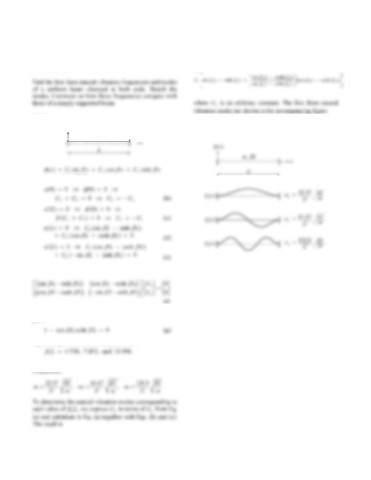
Problem 17.1
Solution:
m, EI
(x)
Cx
4cosh
(a)
Rewrite Eqs. (d) and (e) in matrix form:
Setting the determinant of the coefficient matrix to zero
gives
Equation (g) is solved numerically to obtain
for n = 1, 2, and 3. Eq. (17.3.8) then gives the natural
n
x
()
The natural vibration frequencies of the clamped beam
are higher than for the simply supported beam.
2
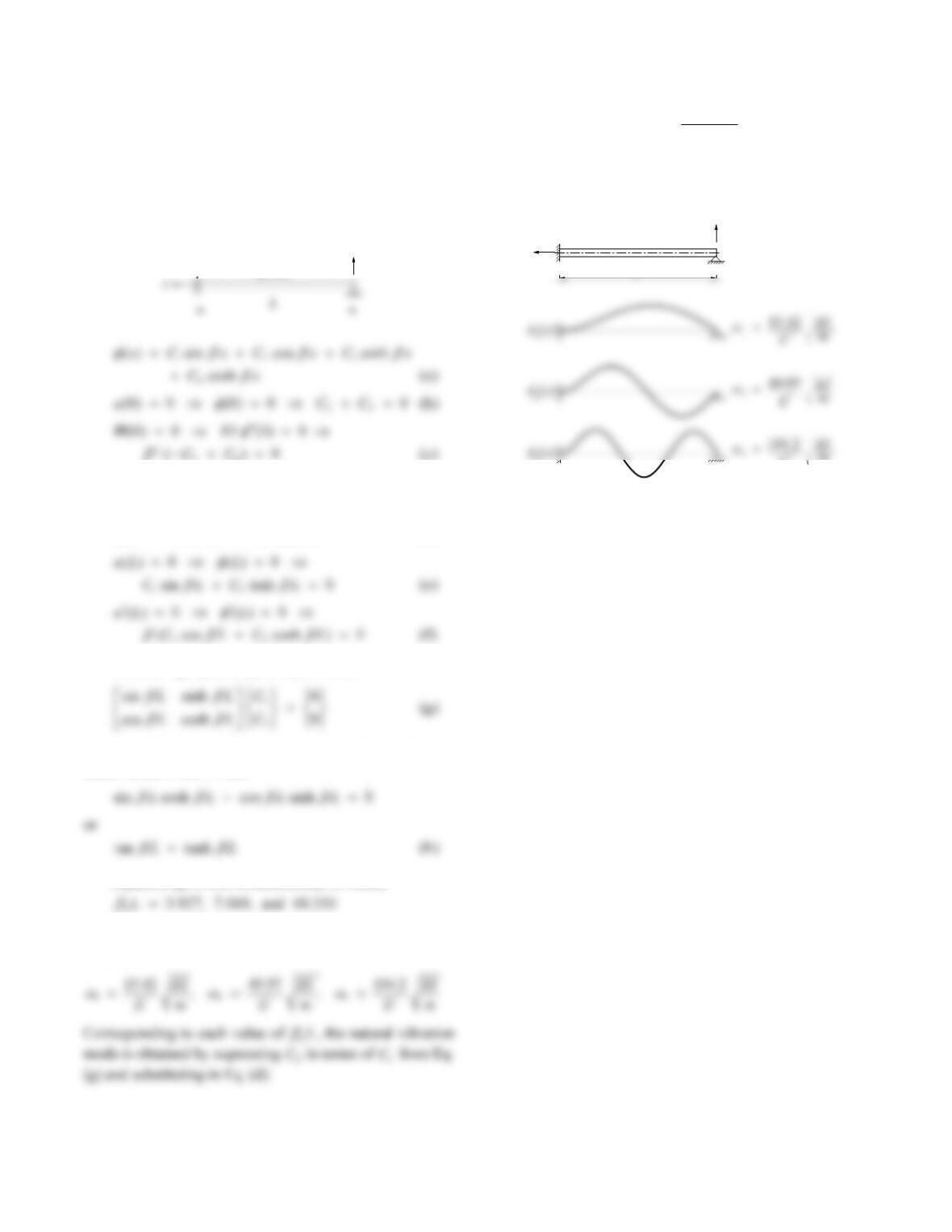
Problem 17.2
Find the first three natural vibration frequencies and modes
of a uniform beam clamped at one end and simply
supported at the other. Sketch the modes.
Solution:
m, EI
(x)
These two equations gives
C
C
24
0
and the general
solution reduces to
13
( ) sin sinh
x
CxC x
(d)
Rewrite Eqs. (e) and (f) in matrix form:
For a nontrivial solution, the determinant of the coefficient
matrix must be zero. Thus
Equation (g) is solved numerically to obtain
for n = 1, 2, and 3. Eq. (17.3.8) then gives the natural
frequencies:
1
sin
() sin sinh
sinh
n
nn n
n
L
x
Cx x
L
where
C
1 is an arbitrary constant. The first three natural
vibration modes are shown in the accompanying figure.
3(x)
m
L
x
m, EI
L
(x)
+
x
3
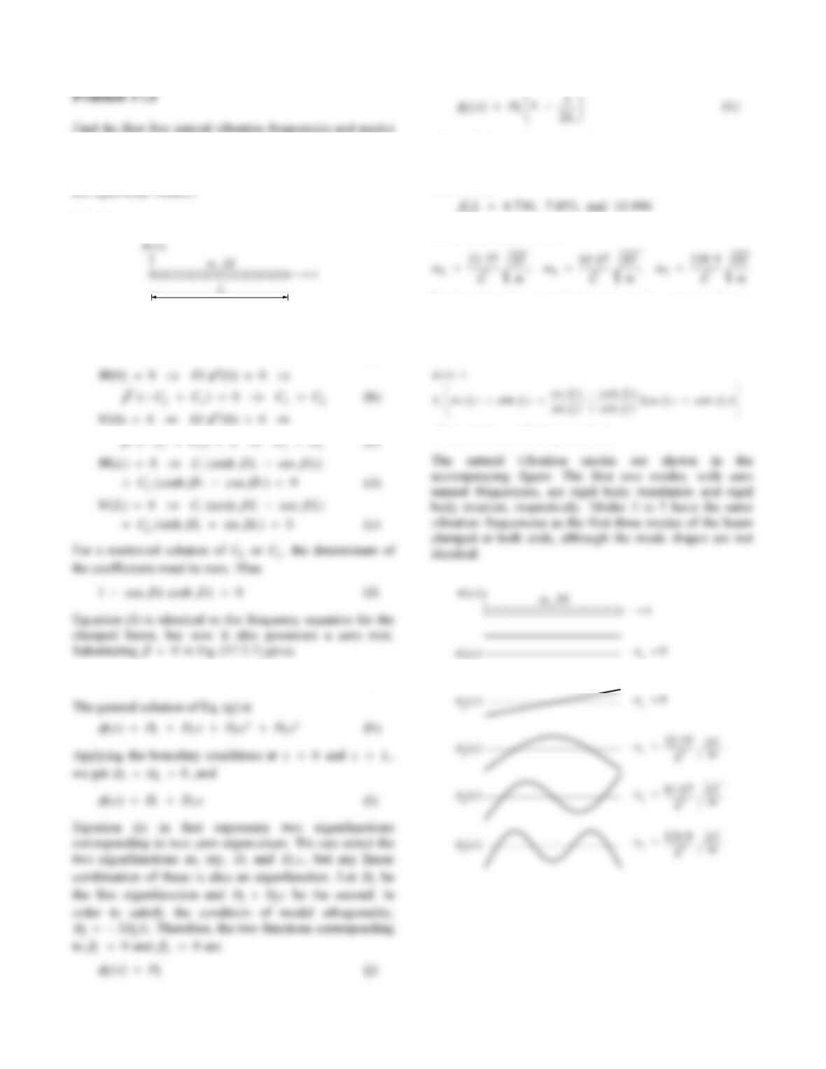
Find the first five natural vibration frequencies and modes
of a uniform beam free at both ends. Sketch the modes.
Comment on how these frequencies compare with those for
a beam clamped at both ends. (Hint: The first two modes
are rigid-body modes.)
Solution:
L
12 3
( ) sin cos sinh
x
CxC xC x
Cx
4cosh
(a)
L
L
C
C
3
iv() 0x
(g)
x
x
L
where D1 is an arbitrary constant.
The non-zero roots of Eq. (f) can be obtained
numerically:
nL
for n = 3, 4, and 5. Thus
To determine the natural vibration mode corresponding to
each non-zero value of
nL, we express
C
2 in terms of
C
1
from Eq. (e) and substituted in Eq. (a) together with Eqs.
(b) and (c) to obtain:
where
C
1 is an arbitrary constant.
1(x)
4
Problem 17.4
x
L
Solution:
1. Natural vibration frequencies and modes.
2
() () 0
nnn
qt qt
(b)
Multiplying both sides of Eq. (d) by m
x
x
n
() ()
and
2
00
() () (,0) (0) ()[ ()]
LL
nnn
mx x ux dx q mx x dx
Substituting
n
x
()
in Eqs. (17.5.3a) and (e) gives
32
0
2
(0) sin 4 3
48
L
n
n
mW nx
qxLxdx
MEI L
Because the initial velocity is zero,
4. Modal responses.
5. Total response.
Substituting Eqs. (a) and (j) gives
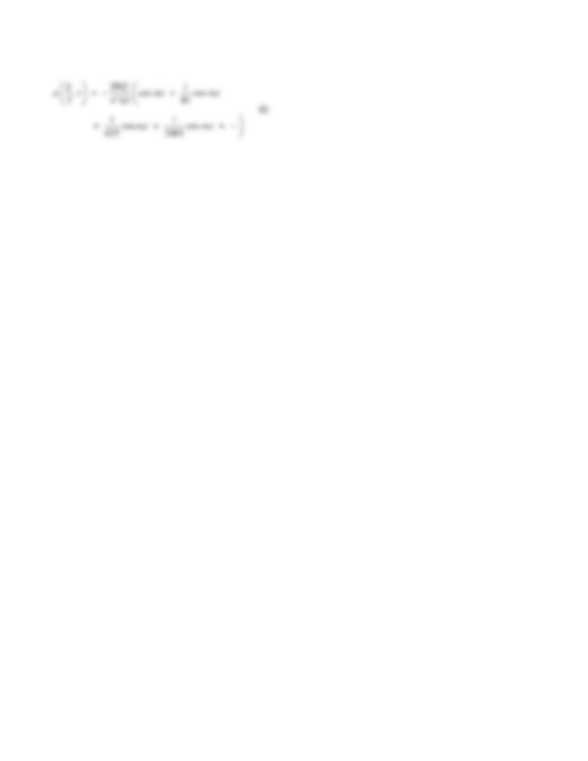
5
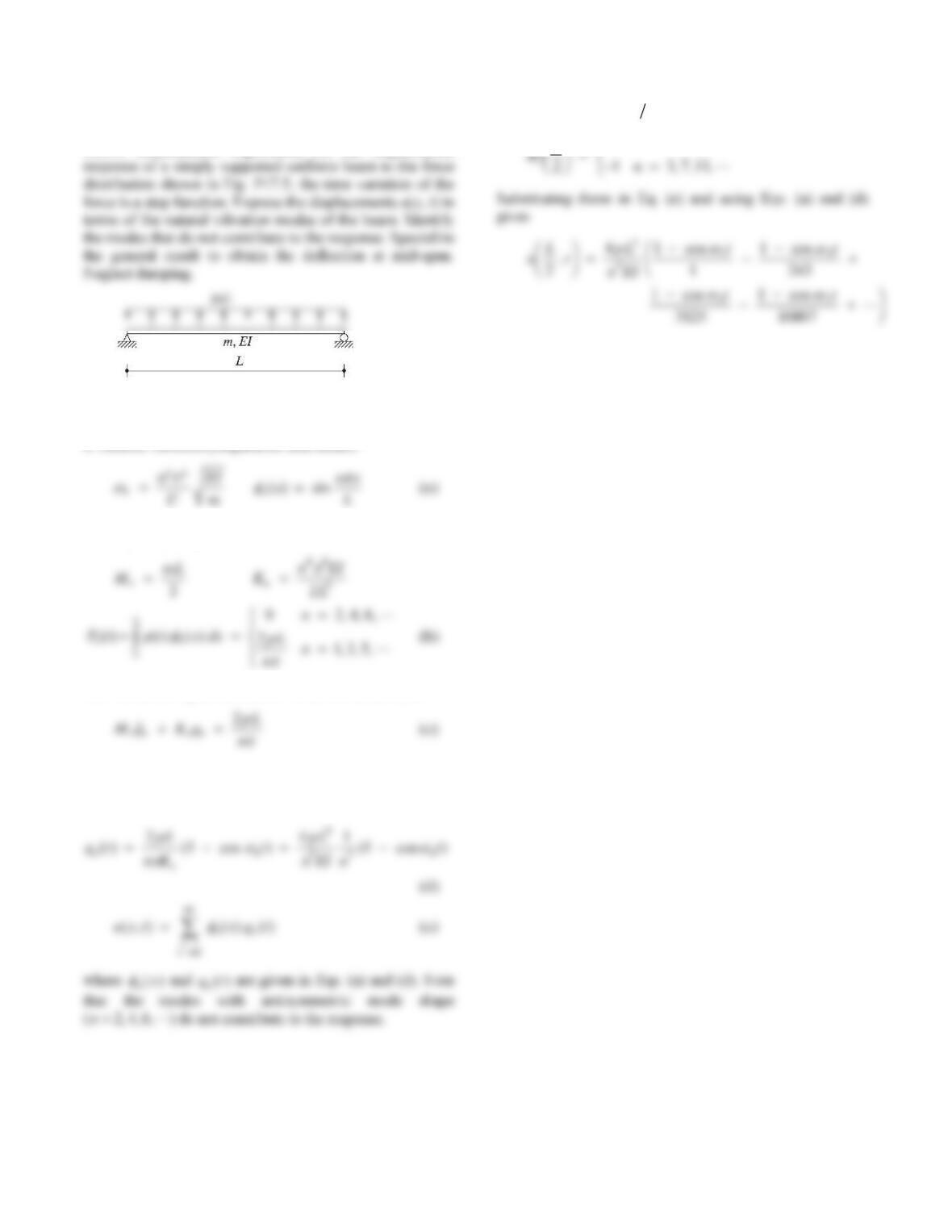
6. Specialize for mid-span deflection.
6
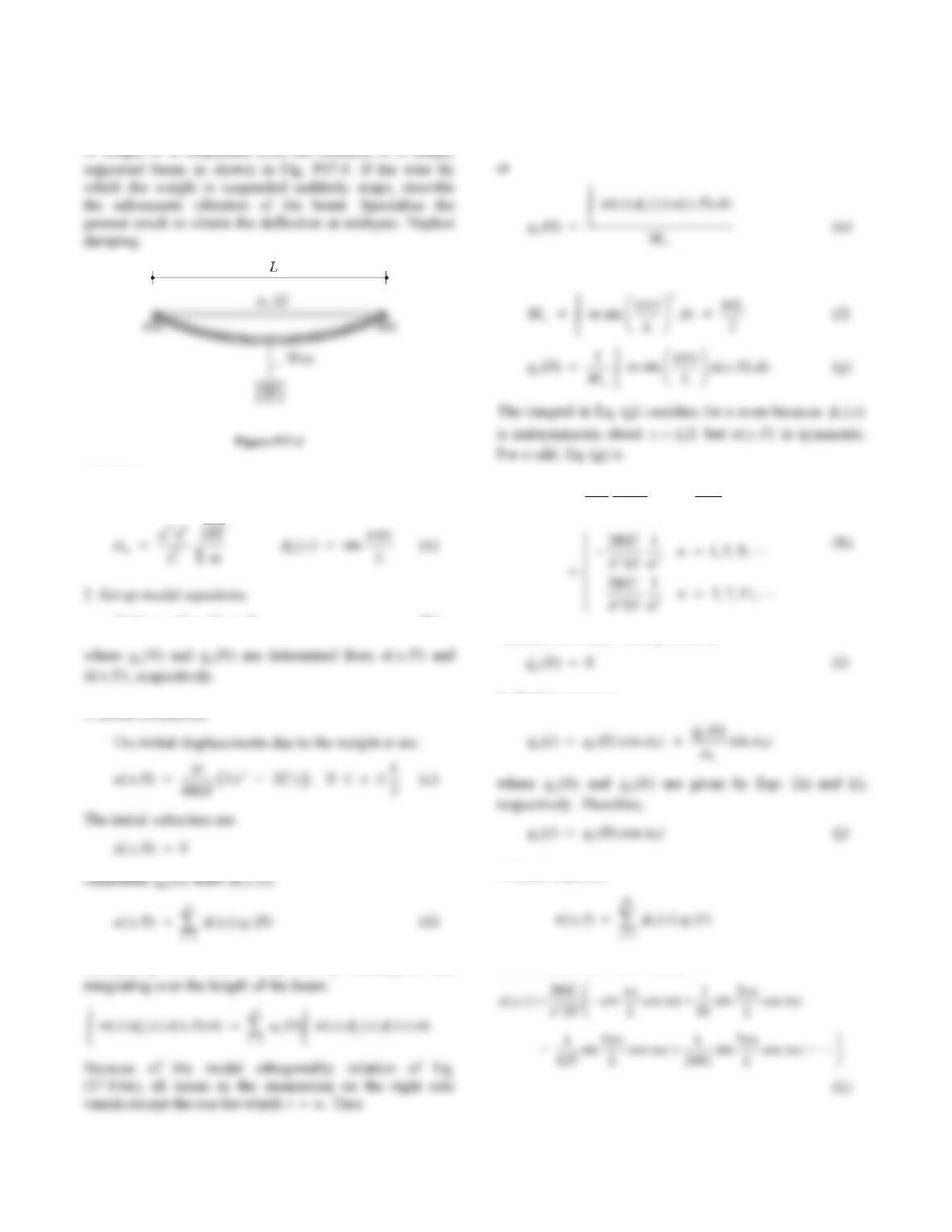
Problem 17.5
Derive mathematical expressions for the displacement
Figure P17.5
Solution:
1. Natural vibration frequencies and modes.
2. Set up modal equations.
The nth modal equation (where n is an odd number) is
3. Determine dynamic response.
The solution to Eq. (c) is:
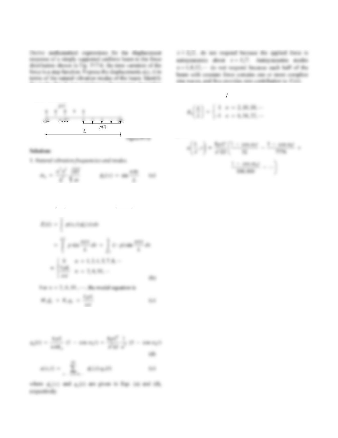
4. Specialize for
x
L
2.
1 1,5,9,
n
L
7
Problem 17.6
the modes that do not contribute to the response. Specialize
the general result to obtain the deflection at quarter span.
Neglect damping.
2. Set up modal equations.
2
nmL
M
44
3
2
nnEI
KL
3. Determine dynamic response.
The solution to Eq. (c) is
Note that only modes n2610,, , contribute to the
response. Modes n
135,,, , which are symmetric about
sine waves, and thus provides zero contribution to
P
t
n().
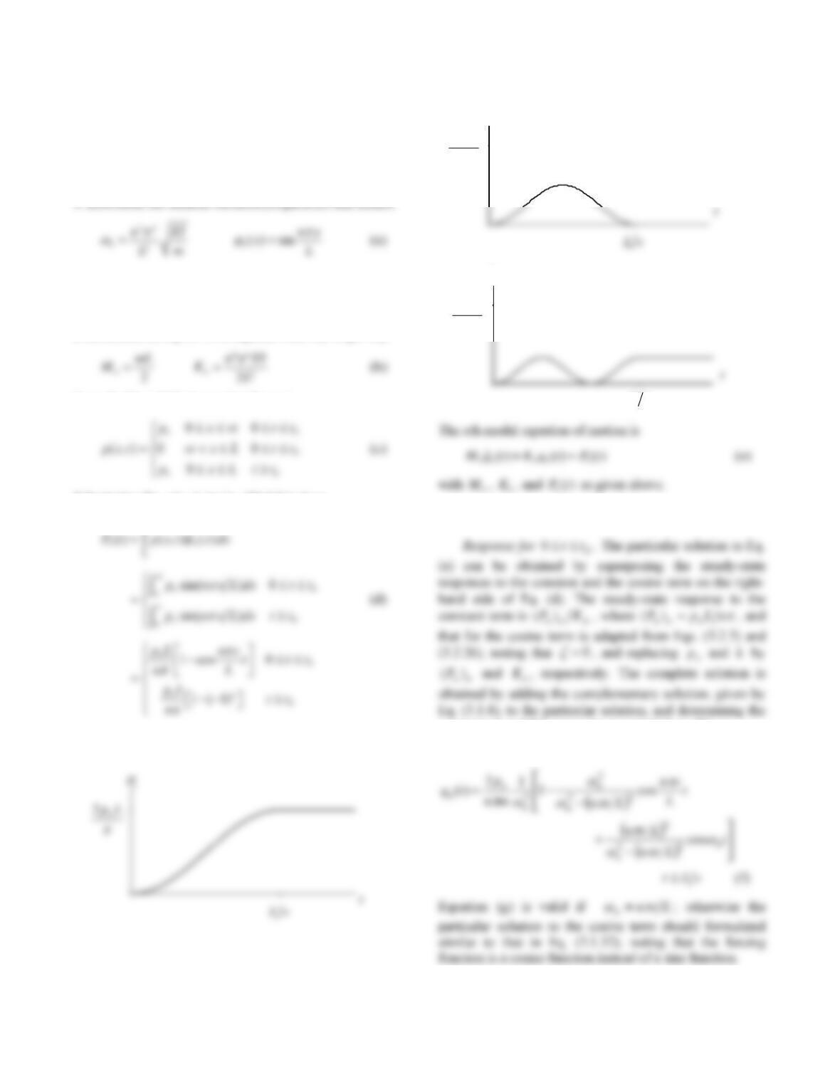
4. Specialize for
x
L
4.
Substituting these in Eq. (e) and using Eqs. (a) and (d)
gives
8
Problem 17.7
Solve Problem 8.25 considering all natural vibration modes
of the bridge.
Solution:
2. Set up the modal equations.
Substituting )(x
n
in Eq. (17.5.3a) gives n
M, which
is substituted in Eq. (17.5.5) together with 2
n
to get n
K:
From Problem 8.25, the applied force is
Substituting for ),( txp in Eq. (17.5.3c) gives
L
Equation (d) is plotted next for n = 1, 2, and 3:
3. Solve the modal equations.
constants A and B by imposing zero initial conditions.
The result is
2o
pL
2
P
2o
pL
vL
3
P
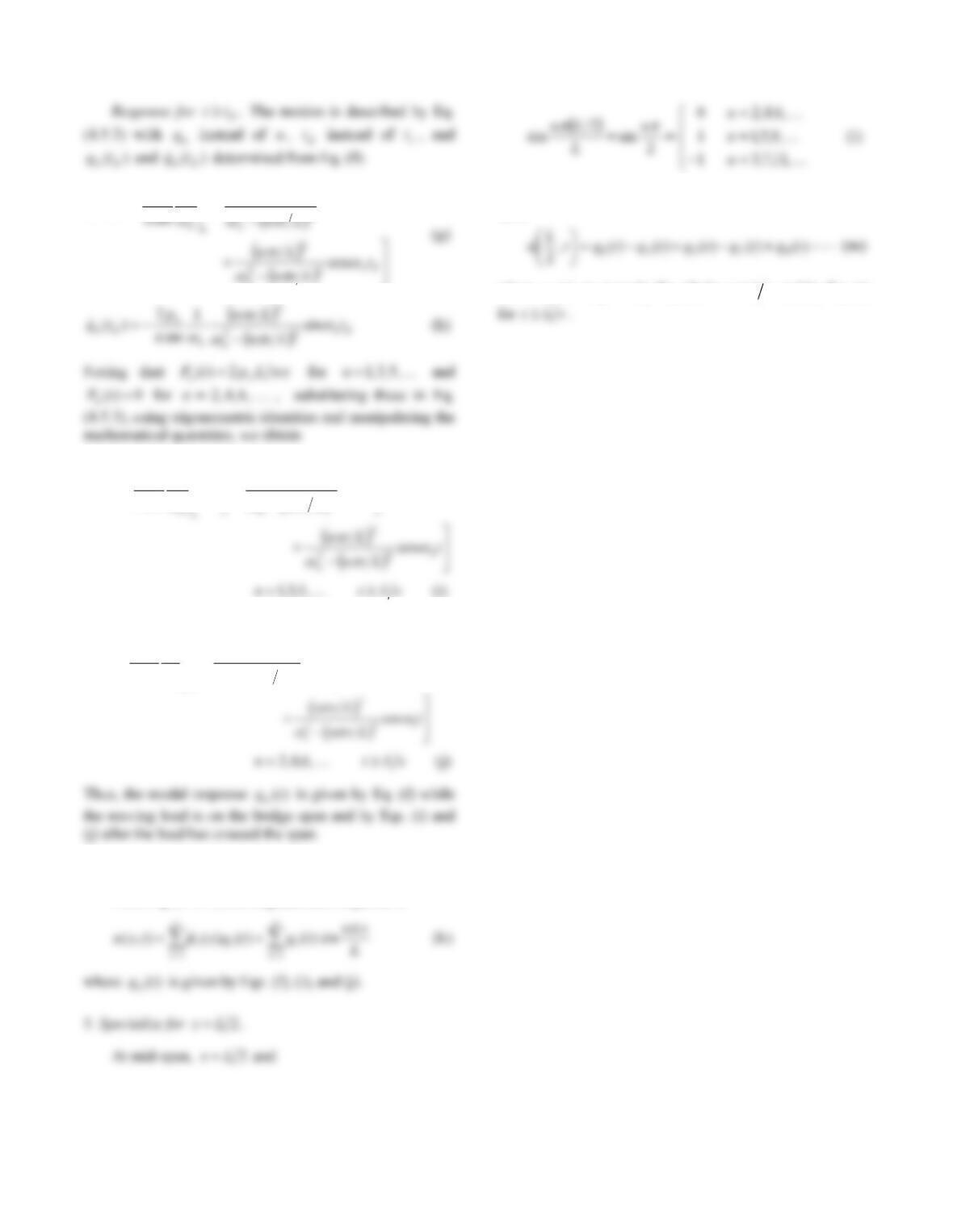
9
n
n
n
o
dn
p
tq
)1(1
1
2
)(
2
2
2
2
tt
Lvn
mn
p
tq
dn
n
n
o
n
)(cos)1(12
1
2
)(
2
2
2
2
(i) ,5,3,1 vLtn
and
2
22
2
21
() 1 ( 1) cos ( )
n
on
nnd
nn
p
qt t t
nm nvL
4. Determine the displacement response.
From Eq. (17.5.7) the displacement response is
Substituting Eq. (l) into Eq. (k) gives the deflection at mid-
span:
where )(tqn is given by Eq. (f) for vLt and by Eq. (i)
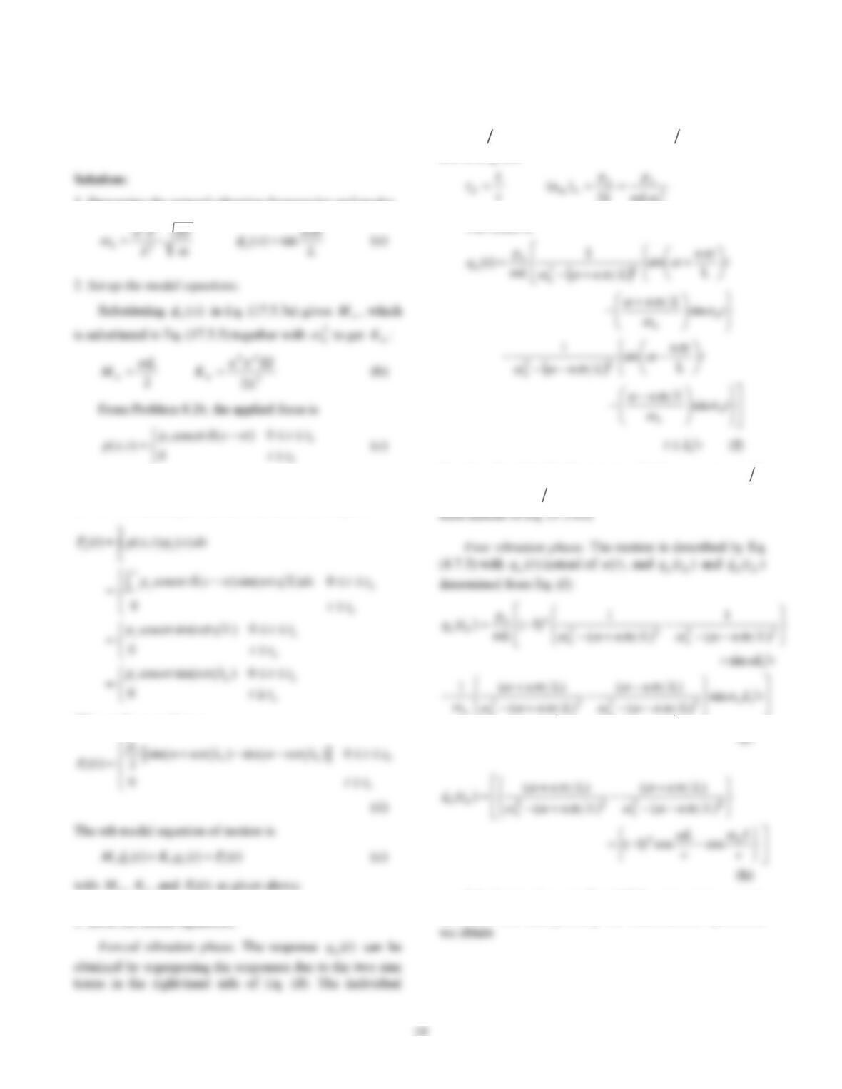
Problem 17.8
Solve Problem 8.26 considering all natural vibration modes
of the bridge.
1. Determine the natural vibration frequencies and modes.
22
where )( vtx
is the Dirac delta function centered at
vt
x
. Substituting for ),( txp in Eq. (17.5.3c) gives
This can be re-written as
n
responses are adapted from Eq. (3.1.6b) by changing the
notation from )(tu to )(tqn, substituting for
with
d
ttn
in one case and with d
ttn
in the other,
and noting that
2
n
k
The result is
Based on Eq. (3.1.6b), Eq. (g) is valid if Lvn
n
and Lvn
n
; otherwise Eq. (3.1.13a) should be
nn
(g)
Substituting these in Eq. (4.7.3), using trigonometric
identities, and manipulating the mathematical quantities,
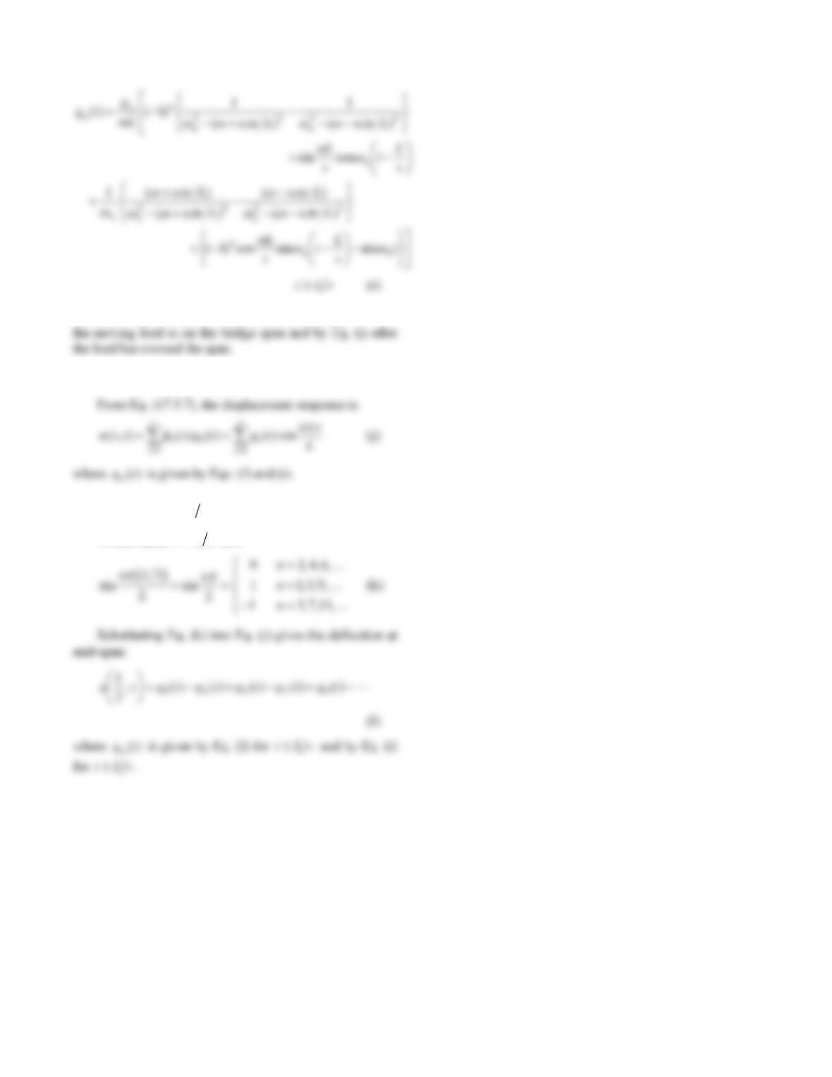
11
Thus, the modal response )(tqnis given by Eq. (f) while
4. Determine the displacement response.
5. Specialize for 2Lx .
At mid-span, 2Lx and
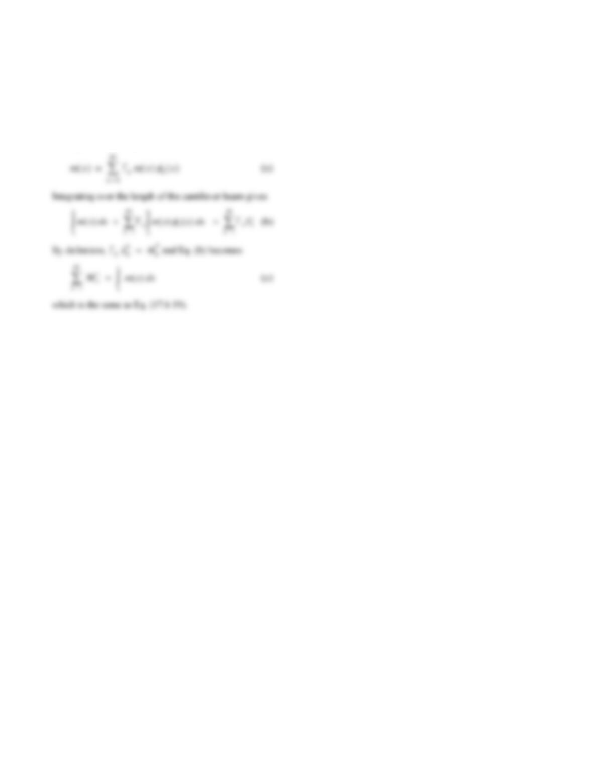
12
Problem 17.9
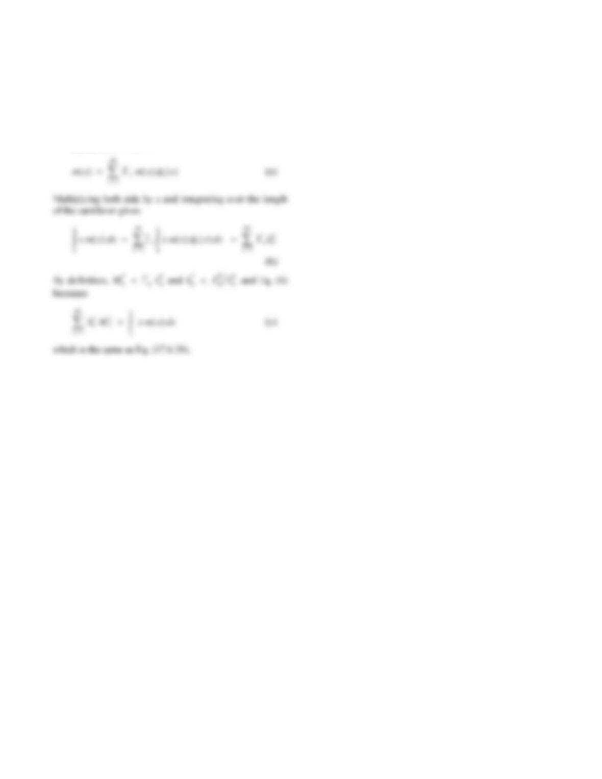
Prove that Eq. (17.6.19) is valid for a vertical cantilever
beam.
Solution:
Equation (17.6.3)
13
Problem 17.10
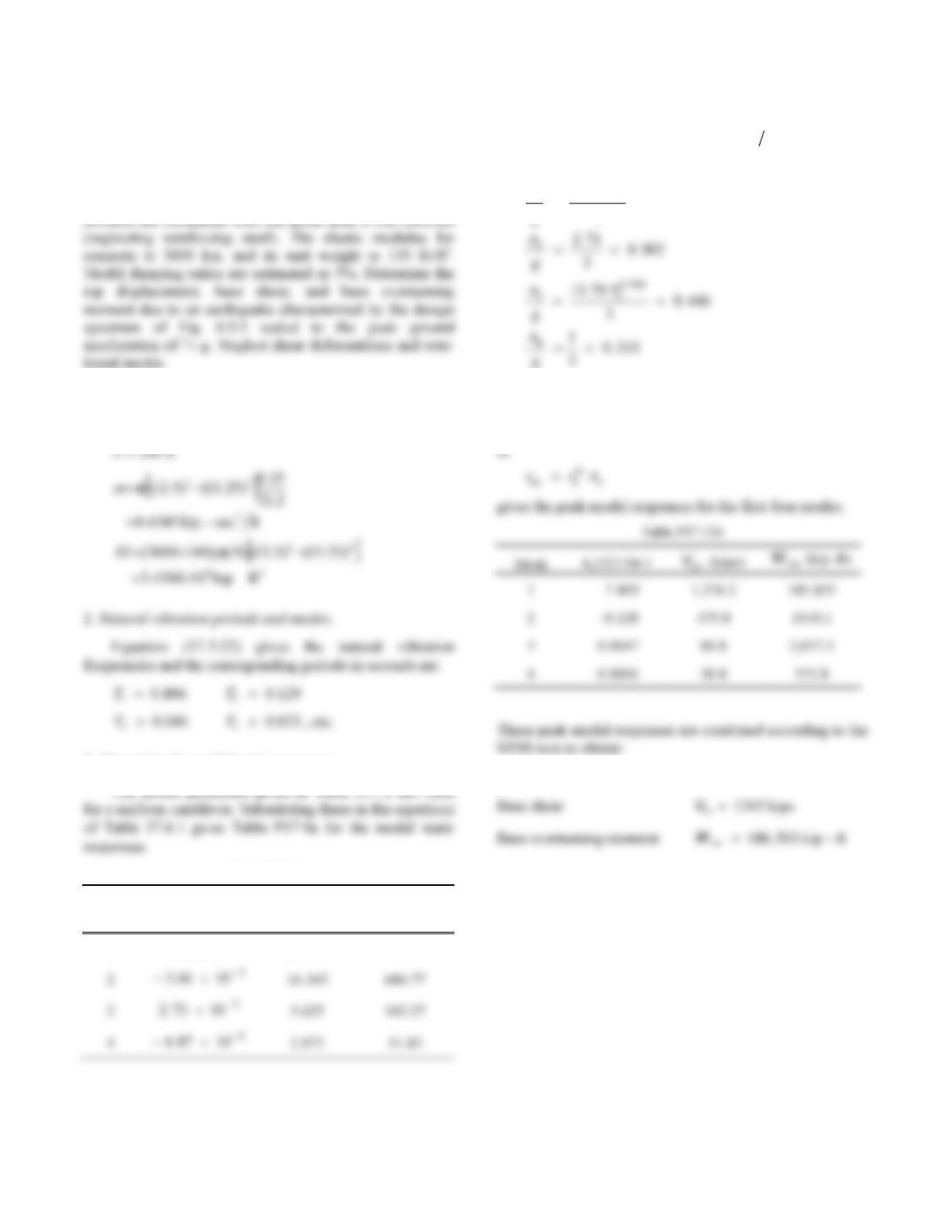
Prove that Eq. (17.6.20) is valid for a vertical cantilever
beam.
Solution:
Equation (17.6.3)
14
Problem 17.11
A free-standing intake–outlet tower 200 ft high has a
uniform hollow circular cross section with outside
diameter 25 ft and wall thickness 1 ft-3 in. Assume that the
tower is clamped at the base and that its mass and flexural
Solution:
1. Tower properties.
3. Determine the modal static responses.
Table P17.11a
Mode uL
n
st ()
V
bn
st
M
bn
st
1 0.0258 53.274 7,740
4. Determine spectrum ordinates.
From Fig. 6.9.5, scaled to g31
go
u
, the design
spectrum ordinates are
AT
11
1
180
30 744
g
..
5. Determine peak responses.
For each response quantity r, substituting rn
st and
A
n
Top displacement u
L
o() .7 410 in.