Unit 16 Design Solutions
303
Solutions to Unit 16 Design and Simulation Problems
Problems 16.1 through 16.14 are Mealy sequential circuit design and simulation problems. These problems are of
approximately equal difficulty so that different students can be assigned different problems. In this exercise, students
first complete their designs using gates and D ip-ops. They then test their designs using the SimUaid simulator.
Next, they convert their design to VHDL, synthesize the VHDL code, and download it to a CPLD or FPGA board to
test their design using hardware.
We ask our students to use the following procedure:
(1) Derive a state graph and state table for the assigned problem. Reduce the table to a minimum number of
states. Check the reduced table using the LogicAid state table checker. Encoded solution files are found in
the Lab16 folder on the CD.
(2) Make a state assignment using the guidelines. Derive the transition table, and then derive the D ip-op
input equations and output equation(s) using Karnaugh maps.
operation of the circuit by applying the required test sequences and observing the outputs, being very careful
to read the outputs at the proper time.
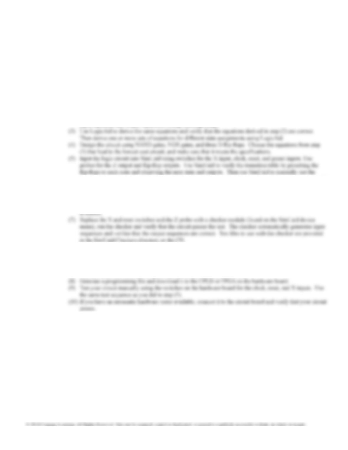
(6) Replace the clock and X input switches with a clock module and an input device. Program the input device
to produce the proper test waveform. Display the simulator timing waveforms for clock, X, Z, and the ip-
op outputs. Print the waveforms and mark the times to read the Z output. Verify that the output sequence
After a proctor has verified that your design is correct and meets specifications, you will implement your design in
hardware using the following steps:
(6) Use SimUaid to generate a VHDL file from your circuit file.
(7) Use the Xilinx ISE software to synthesize the circuit from the VHDL file.
The solution for 16.1 includes the complete SimUaid circuit and the VHDL code generated by SimUaid. The other
solutions only give the logic equations for the ip-op inputs and for Z.
Unit 16 Design Solutions
304
PreA
1
01
X’
S
D
RQ’
Q
A’
0
A
X
1
01
CLK
To generate waveforms, replace the X
switch with and the CLK switch
with
S0
A
B C 0 1
00
01
11
S1
S2
S5
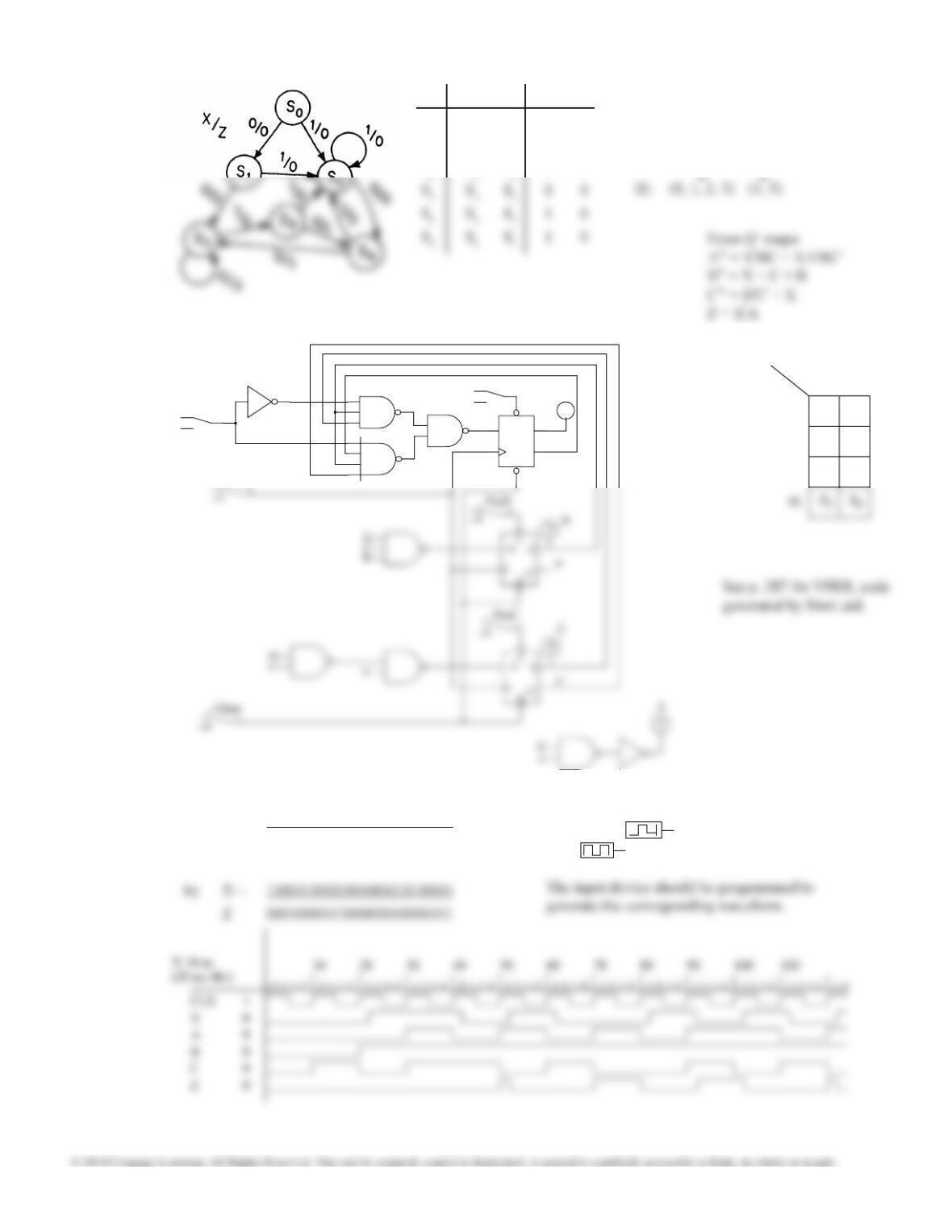
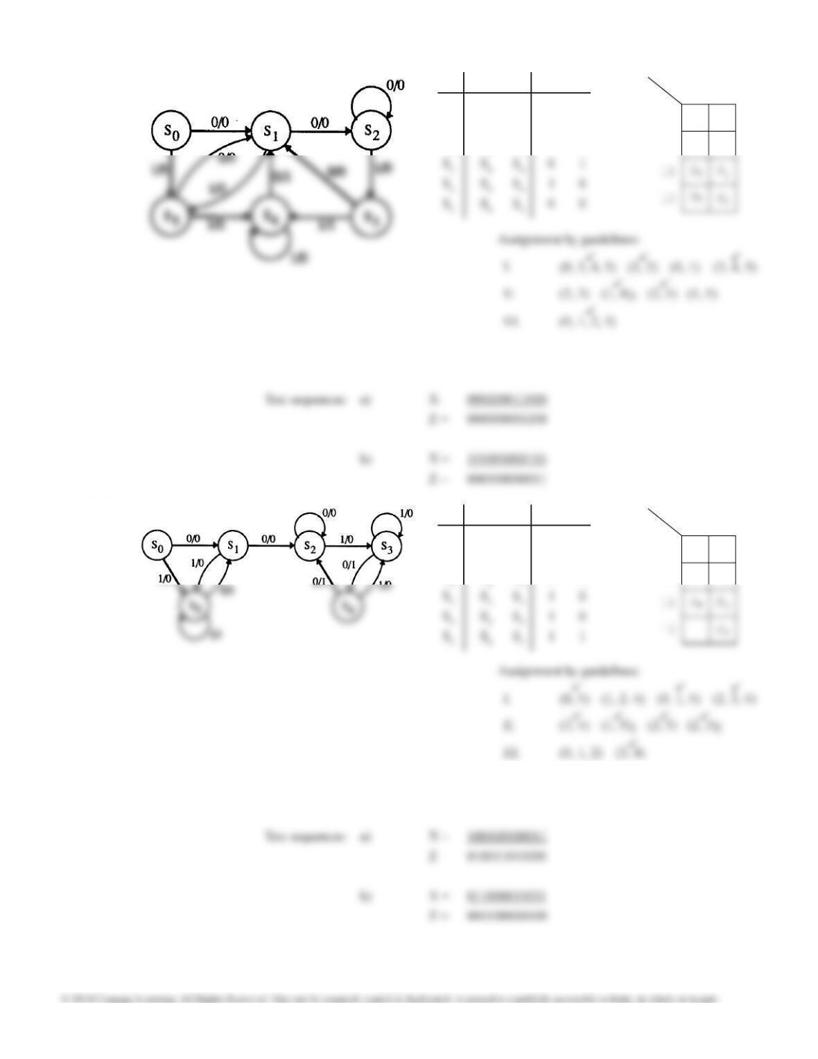
16.1 X = 0 1X = 0 1
S0S1S20 0
S1S3S20 0
S2S4S20 0
I. (1, 3, 4) (2, 5) (0, 1, 2, 4, 5)
II. (1, 2) (2, 3)2(2, 4)2(3, 5)
Assignment by guidelines:
a) X = 001101001010100010010010
Z = 000000010100001001101101
Test sequences:
Unit 16 Design Solutions
305
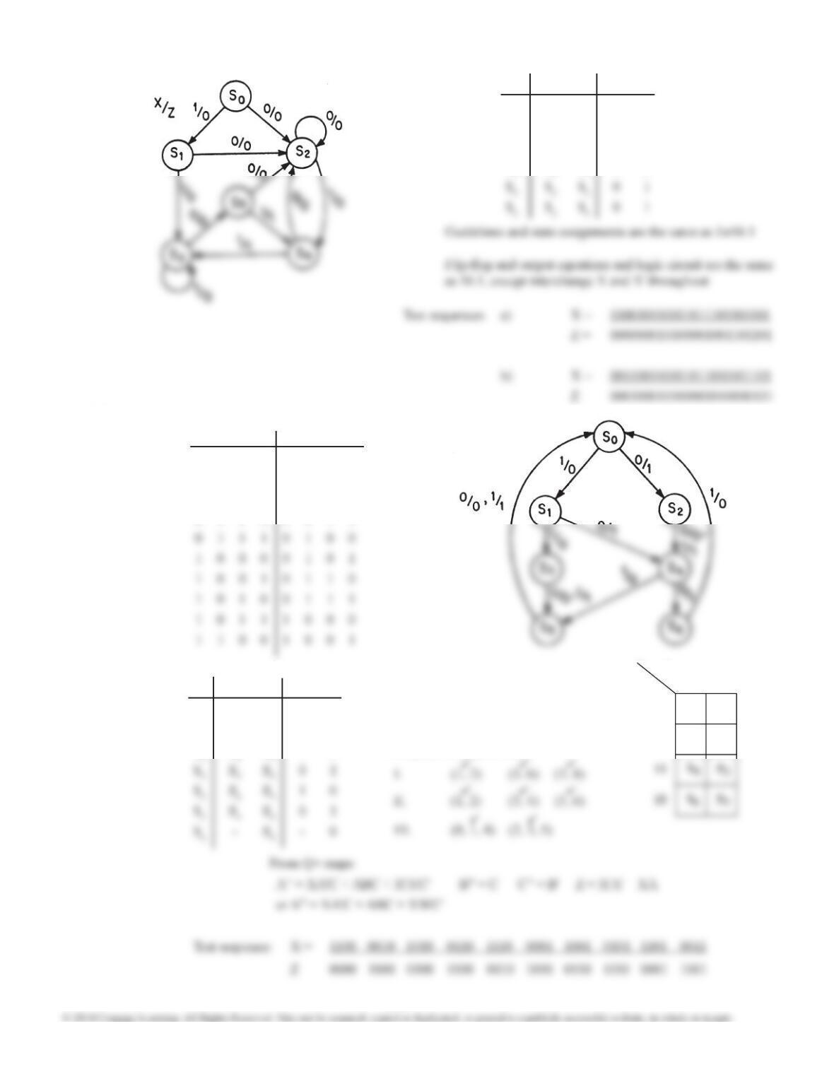
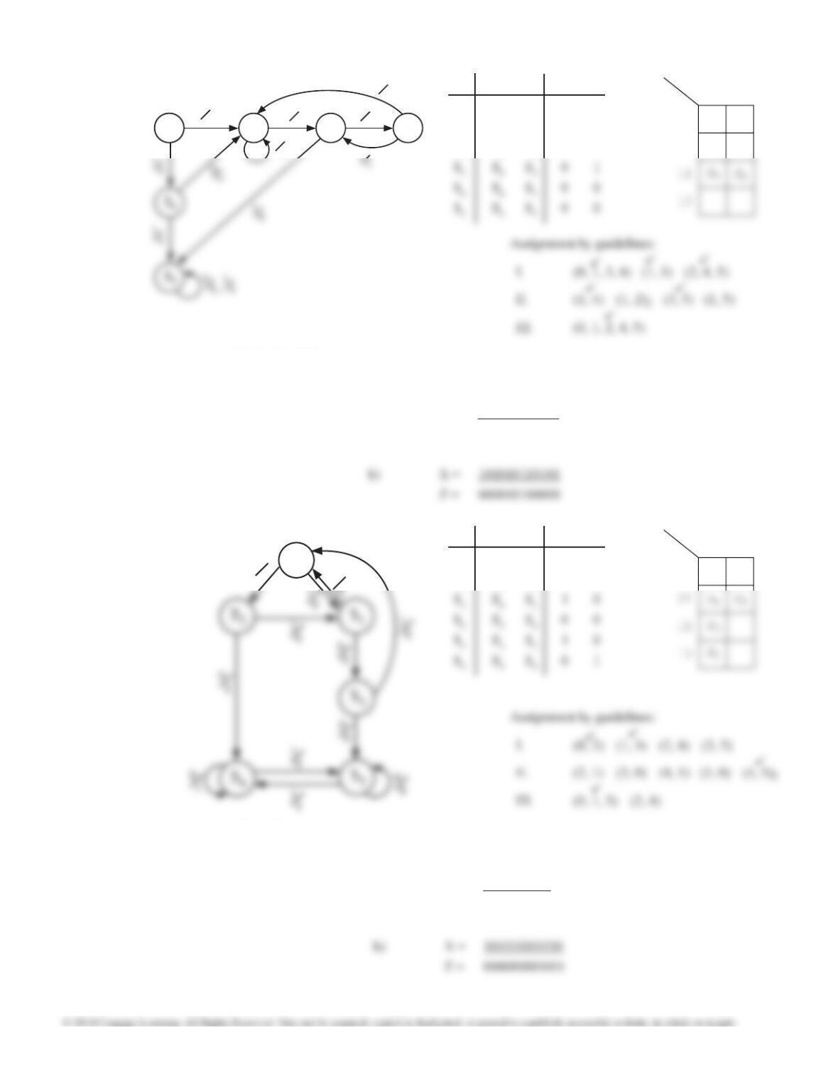
16.2 X = 0 1X = 0 1
S0S2S10 0
S1S2S30 0
S2S2S40 0
S3S5S30 0
16.3
X = 0 1X = 0 1
S0S2S11 0
S1S4S31 0
S2S4S40 1
Assignment by guidelines:
S0
A
B C 0 1
00
01
S1
S2
t3t2t1t0t3t2t1t0
0 0 1 1 0 0 0 0
0 1 0 0 0 0 0 1
0 1 0 1 0 0 1 0
0 1 1 0 0 0 1 1
XZ
Unit 16 Design Solutions
306
16.4
X = 0 1X = 0 1
S0S1S10 1
S1S2S31 0
I. (4, 5) (2, 3)
Assignment by guidelines:
S0
A
B C 0 1
00
01
S1
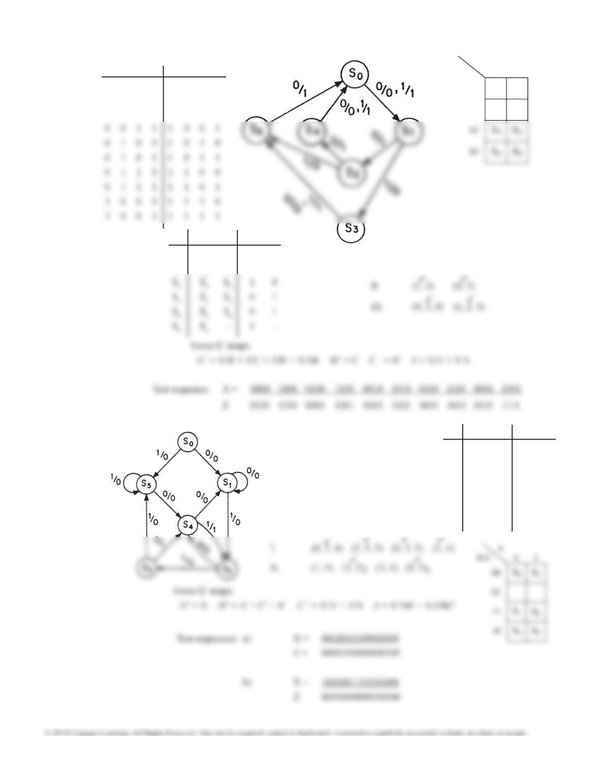
16.5 X = 0 1X = 0 1
S0S1S50 0
S1S1S20 0
S2S4S30 0
S3S4S51 0
S4S1S20 1
S5S4S50 0
Assignment by guidelines:
t3t2t1t0t3t2t1t0
0 0 0 0 0 1 1 0
0 0 0 1 0 1 1 1
0 0 1 0 1 0 0 0
XZ
Unit 16 Design Solutions
307
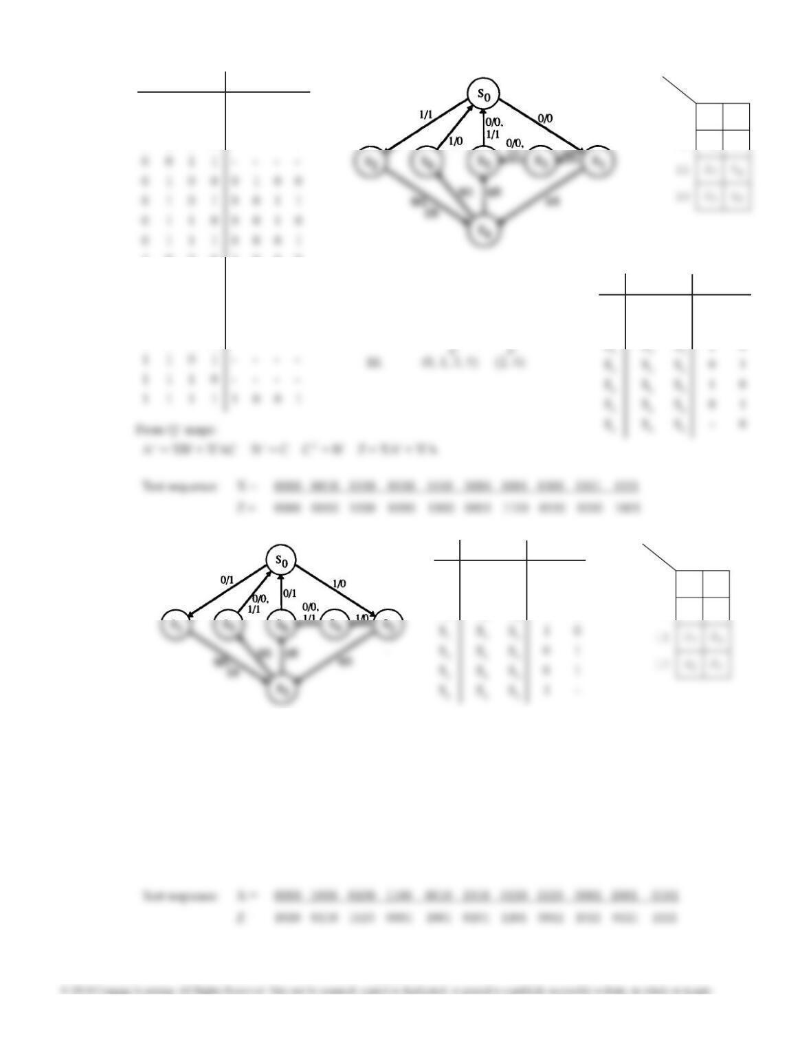
16.6 X = 0 1X = 0 1
S0S1S40 0
S1S1S20 0
S2S3S50 0
From Q+ maps:
A+ = X + AB B+ = AC’ + XA + AB C+ = X’ + A + C’ Z = XA’B
S1S2
00S3
00
0
0
00
1
0
S0
S0
S0
A
B C 0 1
00
01
S1S4
S2
Test sequences: a) X = 010100010110
Z = 000100000100
16.7 X = 0 1X = 0 1
S0S2S10 0
S1S3S00 0
From Q+ maps:
A+ = A + X’B B+ = X’A’B’ C+ = X’C + XC’ Z = XAC + X’AC’ + X’BC’
S0
A
B C 0 1
00
S4
Test sequences: a) X = 0110010100
Z = 0000100111
S0
1
0
0
Unit 16 Design Solutions
308
16.8 X = 0 1X = 0 1
S0S1S50 0
S1S2S50 0
S2S2S30 0
From Q+ maps:
A+ = X’ B+ = X’ + A’ + C C+ = X’A’ + XBC’ + A’C Z = XB’C + X’A’BC
S0
A
B C 0 1
00
01
S3
16.9 X = 0 1X = 0 1
S0S1S50 0
S1S2S50 0
S2S2S30 0
From Q+ maps:
A+ = A’ + B’ + C’ + X B+ = B + X’C C+ = XB + ABC + X’B’C’ Z = X’BC + AB’C’
S0
A
B C 0 1
00
01
S5
S1
Unit 16 Design Solutions
309
16.10
X = 0 1X = 0 1
S0S1S20 1
S1S3S40 1
S0
A
B C 0 1
00
01
S1
S2
I. (1, 2) (3, 4) (5, 6)
II. (1, 2) (3, 4) (5, 6)
Assignment by guidelines:
8 4 -2 -1 8 4 2 1
0 0 0 0 0 0 0 0
0 0 0 1 – – – –
0 0 1 0 – – – –
1 0 0 0 1 0 0 0
1 0 0 1 0 1 1 1
1 0 1 0 0 1 1 0
1 0 1 1 0 1 0 1
1 1 0 0 – – – –
16.11 X = 0 1X = 0 1
S0S1S21 0
S1S3S30 1
S2S3S41 0
From Q+ maps:
A+ = X’B’C’ + XA’BC’ + X’A’BC B+ = C’ C+ = B Z = XA + X’A’
S0
A
B C 0 1
00
01
S6
S5
I. (1, 2) (5, 6) (3, 4)
II. (1, 2) (3, 4) (5, 6)
Assignment by guidelines:
III. (0, 2, 3) (1, 4, 5)
Unit 16 Design Solutions
310
16.12 X = 0 1X = 0 1
S0S1S20 1
S1S3S31 0
S2S3S40 1
S3S5S60 1
From Q+ maps:
A+ = X’B’C’ + XA’BC’ + X’A’BC B+ = C’ C+ = B Z = X’A + XA’
Test sequence: X = 0000 1000 0100 1100 0010 1010 0110 1110 0001 1001 0101
Z = 0101 1001 0001 1110 0110 1010 0010 1100 0100 1000 0000
16.13 X = 0 1X = 0 1
S0S1S00 0
S1S2S00 0
From Q+ maps:
A+ = X’C + A B+ = XA C+ = X’A’C’ + XAC’ + B Z = X’BC’
S0
A
B C 0 1
00
S2
Test sequences: a) X = 100100110101
Z = 000000000010
XZ
0 0 0 0 1 0 1 0
0 0 0 1 1 0 0 1
0 0 1 0 1 0 0 0
0 0 1 1 0 1 1 1

Unit 16 Design Solutions
311
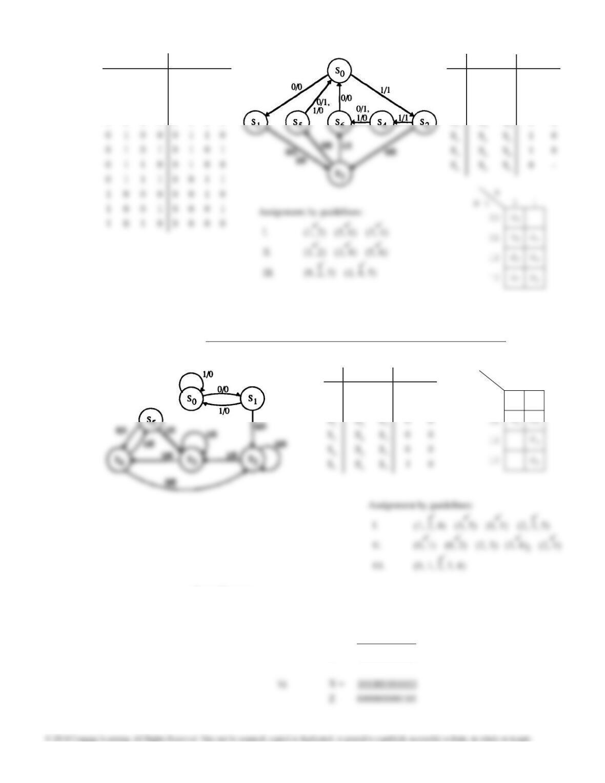
16.14 X = 0 1X = 0 1
S0S1S00 0
S1S4S20 1
S2S3S20 1
S3S2S31 0
S0
A
B C 0 1
00
01
11
S4
S1
S2
— This file has been automatically generated by SimUAid.
library ieee;
use IEEE.STD_LOGIC_1164.ALL;
use IEEE.STD_LOGIC_UNSIGNED.ALL;
use IEEE.STD_LOGIC_ARITH.ALL;
X_p, Vnet_8, Vnet_9, Vnet_10, Vnet_11, Vnet_12, Vnet_13, A_p, Vnet_14, Vnet_15: STD_LOGIC;
begin
VHDL_Device_0: Dipop port map (CLK, Vnet_5, PreB, Clear, Vnet_3, B_p);
VHDL_Device_1: Dipop port map (CLK, Vnet_6, PreC, Clear, Vnet_4, C_p);
VHDL_Device_2: nand2 port map (Vnet_0, Vnet_1, Vnet_2);
VHDL_Device_3: nand4 port map (X, A_p, Vnet_3, C_p, Vnet_1);
VHDL_Device_4: nand3 port map (X_p, C_p, B_p, Vnet_5);
VHDL_Device_5: nand2 port map (Vnet_7, X_p, Vnet_6);
VHDL code for Problem 16.1 automatically generated by SimUaid follows. This code can be synthesized
and downloaded to a CPLD or FPGA board for testing.

Unit 16 Design Solutions
312