
QdotC
600
500
400
300
200
⎛
⎜
⎜
⎜
⎜
⎜
⎝
⎞
⎟
⎟
⎟
⎠
−BTU
sec
⋅:=tC
40
30
20
10
0
⎛
⎜
⎜
⎜
⎜
⎜
⎝
⎞
⎟
⎟
⎟
⎠
:=
The following vectors refer to Parts (a)-(e):
THTσ
:=Tσ70 459.67+( ) rankine⋅:=
The discussion at the top of the second page of the solution to the
preceding problem applies equally here. In each case,
15.5
Wdotlost.evap Tσmdot⋅S2S1
−
()
⋅
…:=
608

117.7
118.9
⎛
⎜
⎞
From these values we must find the
corresponding entropies from Fig. G.2.
From the results of Pb. 9.9, we find:
⎯
⎯
⎯
⎯
H1H4
:=S40.07892 BTU
lbmrankine⋅
⋅:=H437.978 BTU
lbm
⋅:=
For sat. liquid at the condenser temperature:
S2Svap
:=Svap
0.22244
0.22325
0.22418
0.22525
0.22647
⎛
⎜
⎜
⎜
⎜
⎜
⎝
⎞
⎟
⎟
⎟
⎠
BTU
lbmrankine⋅
⋅:=Sliq
0.04715
0.04065
0.03408
0.02744
0.02073
⎛
⎜
⎜
⎜
⎜
⎜
⎝
⎞
⎟
⎟
⎟
⎠
BTU
lbmrankine⋅
⋅:=
H2Hvap
:=Hvap
107.320
105.907
104.471
103.015
101.542
⎛
⎜
⎜
⎜
⎜
⎜
⎝
⎞
⎟
⎟
⎟
⎠
BTU
lbm
⋅:=Hliq
21.486
18.318
15.187
12.090
9.026
⎛
⎜
⎜
⎜
⎜
⎜
⎝
⎞
⎟
⎟
⎟
⎠
BTU
lbm
⋅:=
For sat. liquid and vapor at the evaporator temperature, Table 9.1:
Wdotideal QdotC
THTC
−
TC
⋅
⎛
⎜
⎝
⎞
⎠
→
⎯
⎯⎯⎯⎯⎯⎯
⎯
:=TCtC459.67+
()
rankine⋅:=
609
0.227
0.237
⎛
⎜
⎝
⎞
⎠
8.653
3.146
⎛
⎜
⎝
⎞
⎠
Wdotlost.comp Tσmdot⋅S3S2
−
()
⋅
⎡
⎣
⎤
⎦
→
⎯
⎯⎯⎯⎯⎯⎯
⎯
:=
Qdot H4H3
−
()
mdot⋅
⎡
⎣
⎤
⎦
→
⎯
⎯⎯⎯⎯⎯
⎯
:=
Wdotlost.cond Tσmdot⋅S4S3
−
()
⋅
⎡
⎣
⎤
⎦
→
⎯
⎯⎯⎯⎯⎯⎯
⎯
Qdot−:=
⎡
⎣
⎤
⎦
⎯
⎯
⎡
⎣
⎤
⎦
⎯
⎯
⎯
⎯
The final term accounts for the entropy change of the refrigerated space (an
internal heat reservoir).
⎡
⎣
⎤
⎦
⎯
⎯
⎜
⎜
610

For sat. liquid and vapor at the evaporator temperature, Table 9.1:
Wdotideal 163.375 BTU
sec
=Wdotideal QdotC
THTC
−
TC
⋅
⎛
⎜
⎝
⎞
⎠
:=
QdotC2000−BTU
sec
⋅:=TC30 459.67+( ) rankine⋅:=
THTσ
:=Tσ70 459.67+( ) rankine⋅:=
The discussion at the top of the second page of the solution to Problem
15.4 applies equally here.
15.6
611
The entropy at this point is essentially that of sat. liquid with this
enthalpy; by interpolation in Table 9.1:
H4A H1
:=
Upstream from the throttle (Point 4A) the state is subcooled liquid with
the enthalpy:
Energy balance on heat exchanger:
S30.2475 BTU
lbmrankine⋅
⋅:=
From Fig. G.2 at this enthalpy and 33.11(psia):
H2A 116. BTU
lbm
⋅:= S2A 0.2435 BTU
lbmrankine⋅
⋅:=
From Problem 9.12,
S40.07892 BTU
lbmrankine⋅
⋅:=H437.978 BTU
lbm
⋅:=
For sat. liquid at the condenser temperature:
612
Wdotlost.exchanger Tσmdot⋅S2A S2
−S4A
+S4
−
()
⋅:=
The final term accounts for the entropy change of the refrigerated space (an
internal heat reservoir).
Wdotlost.cond Tσmdot⋅S4S3
−
()
⋅Qdot−:=
Qdot H4H3
−
()
mdot⋅:=
Wdotlost.comp Tσmdot⋅S3S2A
−
()
⋅:=
613
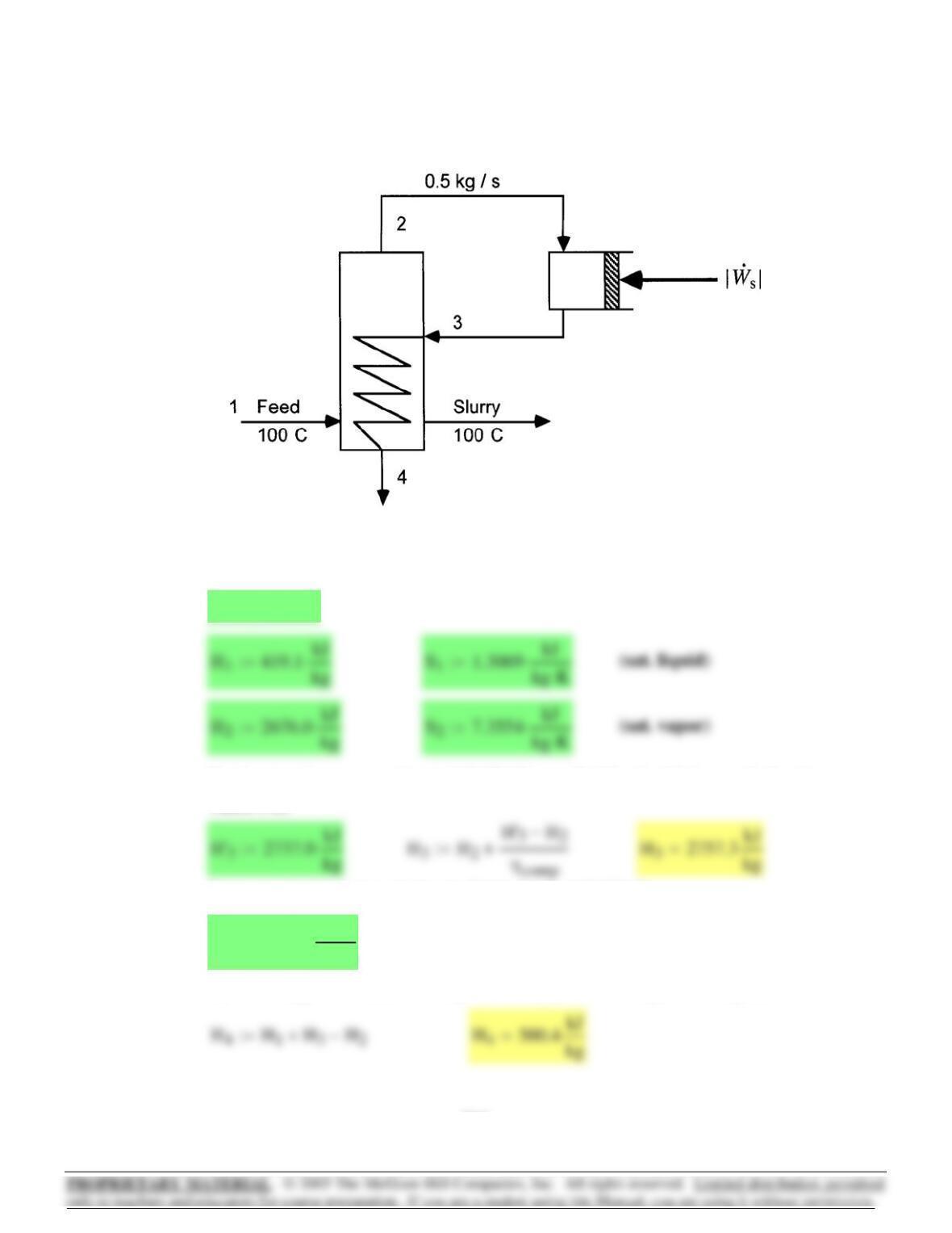
By an energy balance, assuming the slurry passes through unchanged,
S37.4048 kJ
kg K⋅
⋅:=
By more double interpolation in Table F.2 at 143.27 kPa,
For isentropic compression to 143.27 kPa, we find by double interpolation in
Table F.2:
ηcomp 0.75:=
Compression to a pressure at which condensation in coils occurs at
110 degC. Table F.1 gives this sat. pressure as 143.27 kPa
15.7
614
A thermodynamic analysis requires an exact definition of the overall
process considered, and in this case we must therefore specify the source
of the heat transferred to the boiler.
Since steam leaves the boiler at 900 degF, the heat source may be
considered a heat reservoir at some higher temperature. We assume in
the following that this temperature is 950 degF.
The assumption of a different temperature would provide a variation in the
solution.
15.8
Wdotlost.comp mdot Tσ
⋅S3S2
−
()
⋅:=
Wdotlost.evap mdot Tσ
⋅S4S3
−S2
+S1
−
()
⋅:=
Wdotideal mdot H4H1
−TσS4S1
−
()
⋅−
⎡
⎣
⎤
⎦
⋅:=
Sliq 1.4185 kJ
kg K⋅
⋅:=Hlv 2230.0 kJ
kg
⋅:=Hliq 461.3 kJ
kg
⋅:=
This enthalpy is a bit larger than that of sat. liquid at 110 degC; find quality
and then the entropy:
615
The purpose of the condenser is to transfer heat to the surroundings. The
Wlost.turbine TσmS
3S2
−
()
⋅1lb
m
⋅m−
()
S4S2
−
()
⋅+
⎡
⎣
⎤
⎦
⋅:=
⎢
⎥
The turbine
The boiler/heat reservoir combination
For purposes of thermodynamic analysis, we consider the following 4 parts
of the process:
Wideal QH1TC
TH
−
⎛
⎜
⎝
⎞
⎠
⋅:=
QHH2H1
−
()
1⋅lbm
⋅:=
S1
S2
S3
S4
S5
S7
⎛
⎜
⎜
⎜
⎜
⎜
⎜
⎜
⎜
⎝
⎞
⎟
⎟
⎟
⎟
⎟
⎟
⎠
0.3970
1.6671
1.7431
1.8748
0.1326
0.4112
⎛
⎜
⎜
⎜
⎜
⎜
⎜
⎜
⎝
⎞
⎟
⎟
⎟
⎟
⎟
⎠
BTU
lbmrankine⋅
⋅:=
H1
H2
H3
H4
H5
H7
⎛
⎜
⎜
⎜
⎜
⎜
⎜
⎜
⎜
⎝
⎞
⎟
⎟
⎟
⎟
⎟
⎟
⎠
257.6
1461.2
1242.2
1047.8
69.7
250.2
⎛
⎜
⎜
⎜
⎜
⎜
⎜
⎜
⎝
⎞
⎟
⎟
⎟
⎟
⎟
⎠
BTU
lbm
⋅:=
Subscripts below correspond to points on figure of Pb. 8.7.
TσTC
:=TC459.67 80+( ) rankine⋅:=TH459.67 950+( ) rankine⋅:=
We take as a basis 1 lbm of H2O passing through the boiler. Required
property values come from Pb. 8.8.
The ideal work of the process in this case is given by a Carnot engine
operating between this temperature and that of the surroundings, here
specified to be 80 degF.
616

S10 9.521 kJ
kg K⋅
⋅:=H10 796.9 kJ
kg
⋅:=
S94.928 kJ
kg K⋅
⋅:=H9285.4 kJ
kg
⋅:=
S77.544 kJ
kg K⋅
⋅:=H7719.8 kJ
kg
⋅:=
S58.894 kJ
kg K⋅
⋅:=H51009.7 kJ
kg
⋅:=
S49.359 kJ
kg K⋅
⋅:=H41140.0 kJ
kg
⋅:=
Property values:
Refer to Figure 9.7, page 330 The analysis presented here is for
the liquefaction section to the right of the dashed line. Enthalpy and
entropy values are those given in Ex. 9.3 plus additional values from
the reference cited on page 331 at conditions given in Ex. 9.3.
15.9
The absolute value of the actual work comes from Pb. 8.8:
Wlost.pump.heater Tσ1lb
m
⋅S1S5
−
()
⋅mS
7S3
−
()
⋅+
⎡
⎣
⎤
⎦
⋅:=
Wlost.cond.valve Tσ1lb
m
⋅S5
⋅1lb
m
⋅m−
()
S4
⋅− mS
7
⋅−
⎡
⎣
⎤
⎦
⋅Q−:=
617

Wideal ∆Hm⋅()
fs Tσ∆⋅ Sm⋅()
fs
−=SG∆Sm⋅()
fs
Q
Tσ
−=Wlost TσSG
⋅=
______________________________________________________________
Wideal H15 1z−()⋅H9z⋅+ H4
−
⎡
⎣
⎤
⎦
TσS15 1z−()⋅S9z⋅+ S4
−
⎡
⎣
⎤
⎦
⋅−:=
Wideal 489.001−kJ
kg
=
Wout H12 H11
−
()
x⋅:= Wout
kJ
kg
:=
H14 1042.1 kJ
kg
⋅:= S14 11.015 kJ
kg K⋅
⋅:=
H15 1188.9 kJ
kg
⋅:= S15 11.589 kJ
kg K⋅
⋅:=
H6H5
:= S6S5
:= H11 H5
:= S11 S5
:=
H12 H10
:= S12 S10
:= H13 H10
:= S13 S10
:=
Tσ295K:=
The basis for all calculations is 1 kg of methane entering at point 4. All
work quantities are in kJ. Results given in Ex. 9.3 on this basis are:
Fraction of entering methane that is liquefied:
Fraction of entering methane passing through the expander:
On this basis also Eq. (5.26) for Ideal Work, Eq. (5.33) for Entropy
Generation,and Eq. (5.34) for Lost Work can be written:
z 0.113:= x 0.25:=
618
⎡
⎣
⎤
⎦
⎡
⎣
⎤
⎦

Work analysis, Eq. (15.3):
kJ/kg Percent of Σ
(c) Expander: SG.c S12 S11
−
()
x⋅:=
(d) Throttle: SG.d S9z⋅S10 1z−x−()⋅+ S71x−()⋅−
⎡
⎣
⎤
⎦
:=
Entropy-generation analysis:
kJ/kg-K Percent of Σ
619