14.1: PROBLEM DEFINITION
Situation:Thrustofafixed pitch propeller
Find: Reason the thrust decreases with forward speed.
SOLUTION
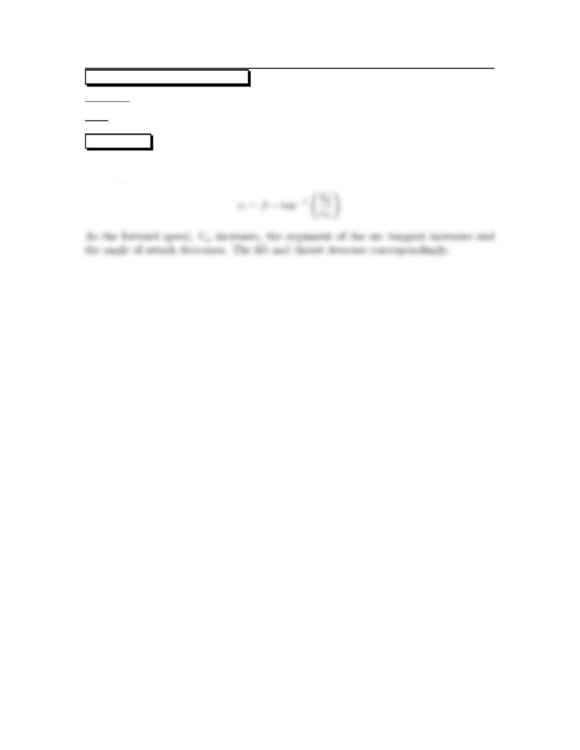
The angle of attack for the propeller blade is the difference between the pitch angle
and angle of flow due to forward motion,
1
14.2: PROBLEM DEFINITION
Situation: Rotational speed of propeller.
Find: Limit on rotational speed.
SOLUTION
As the rotational speed increases, the tip speed increases to the point where com-
2
14.3: PROBLEM DEFINITION
Situation:A3mpropelleroperatesat1100rpmwithnoforwardspeed.
Find: Thrust force.
Properties:ρ=1.05 kg/m3.
PLAN
Use propeller characteristics in Fig. 14.3 (EFM 10e).
SOLUTION
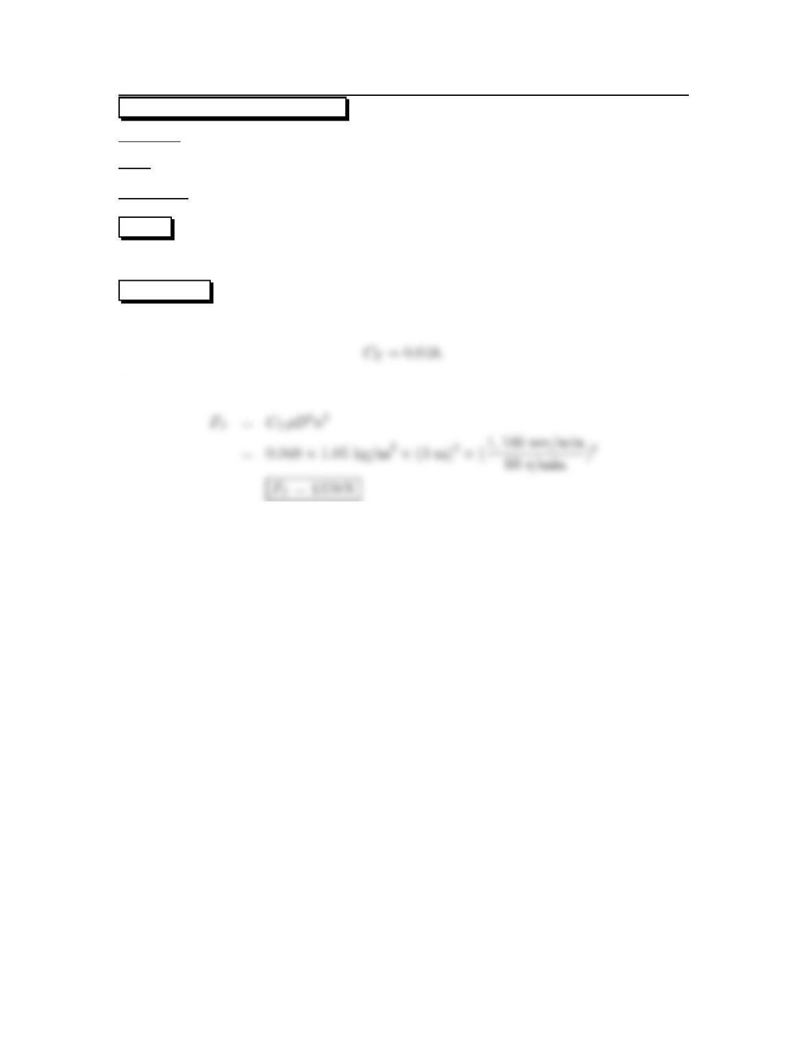
From Fig. 14.3 (EFM 10e) for advance ratio equal to zero.
Propeller thrust force equation
3
14.4: PROBLEM DEFINITION
Situation: A 3 m propeller operates at 1400 rpm with forward speed of 80 km/hr.
Find:(a)Thrust.(b)Power.
Properties:ρ=1.05 kg/m3
PLAN
Use propeller characteristics in Fig. 14.3 (EFM 10e).
SOLUTION
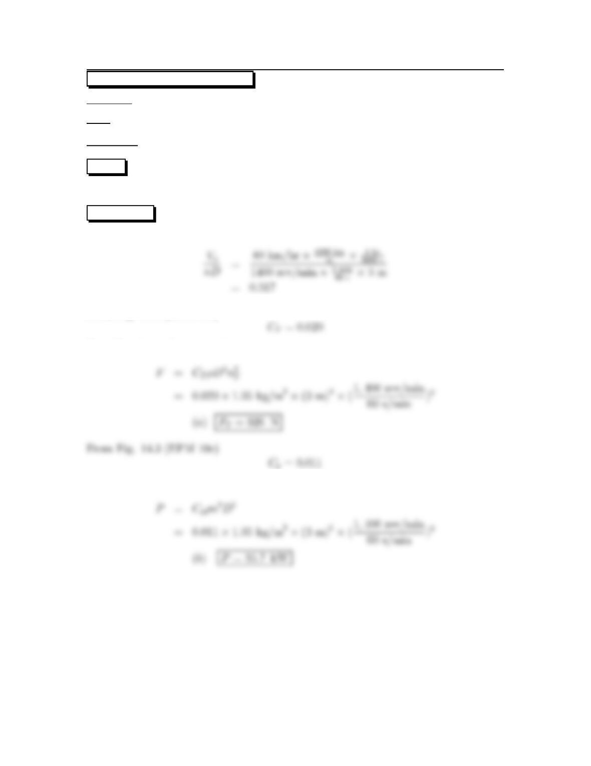
Advance ratio
From Fig. 14.3 (EFM 10e)
Propeller thrust force equation
Propeller power equation
4
14.5: PROBLEM DEFINITION
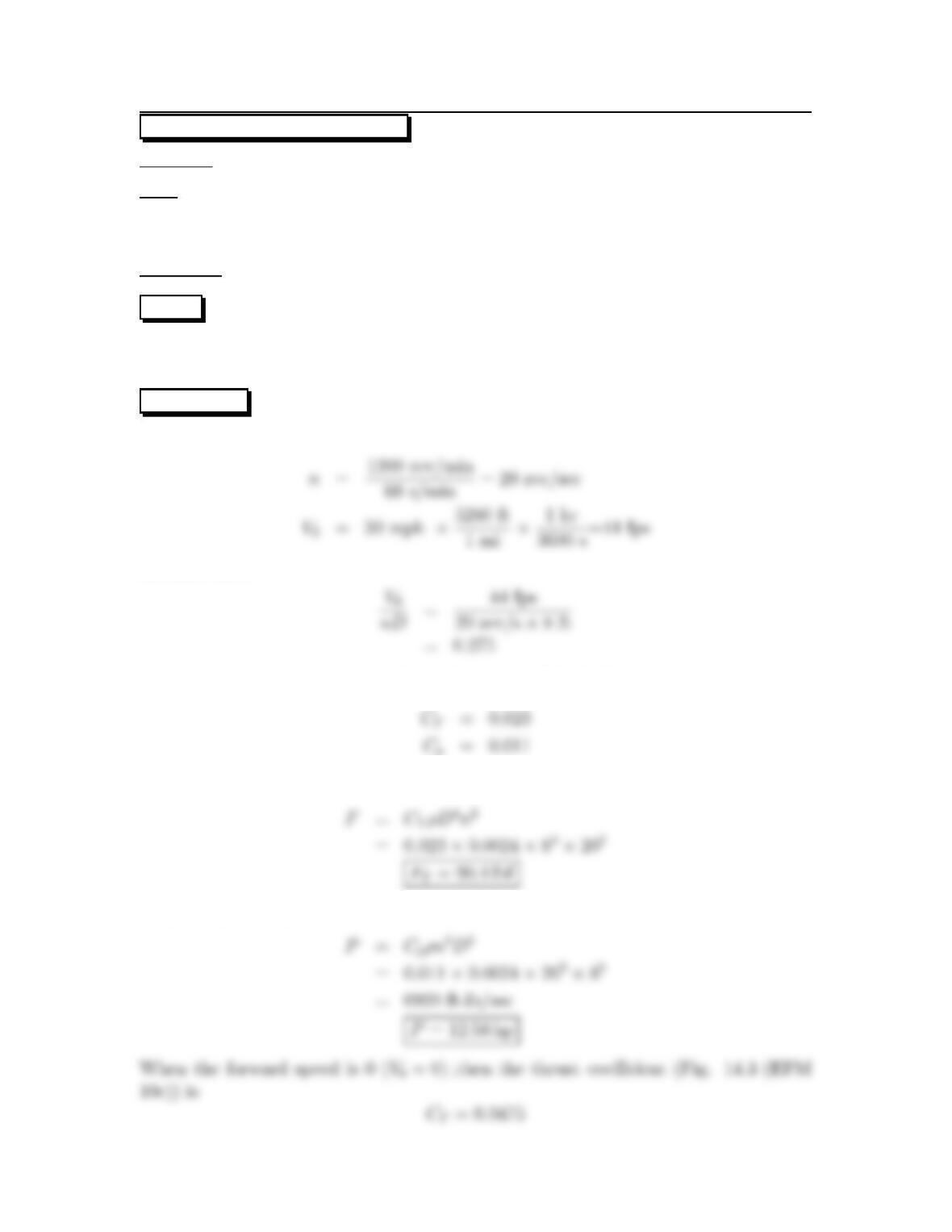
Situation: An 8 ft propeller rotates at 1200 rpm with forward speed of 30 mph.
Find:(a)ThrustforV0=30mph.
(b) Power for (a).
(c) Thrust for V0=0.
Properties:ρ=0.0024 slug/ft3
PLAN
Find advance ratio and use characteristics from Fig. 14.3 (EFM 10e). Apply the
propeller thrust force equation and the propeller power equation.
SOLUTION
Rotational speed and forward velocity.
Advance ratio
Coefficient of thrust and power (from Fig. 14.3 (EFM 10e))
Propeller thrust force equation
Propeller power equation
5
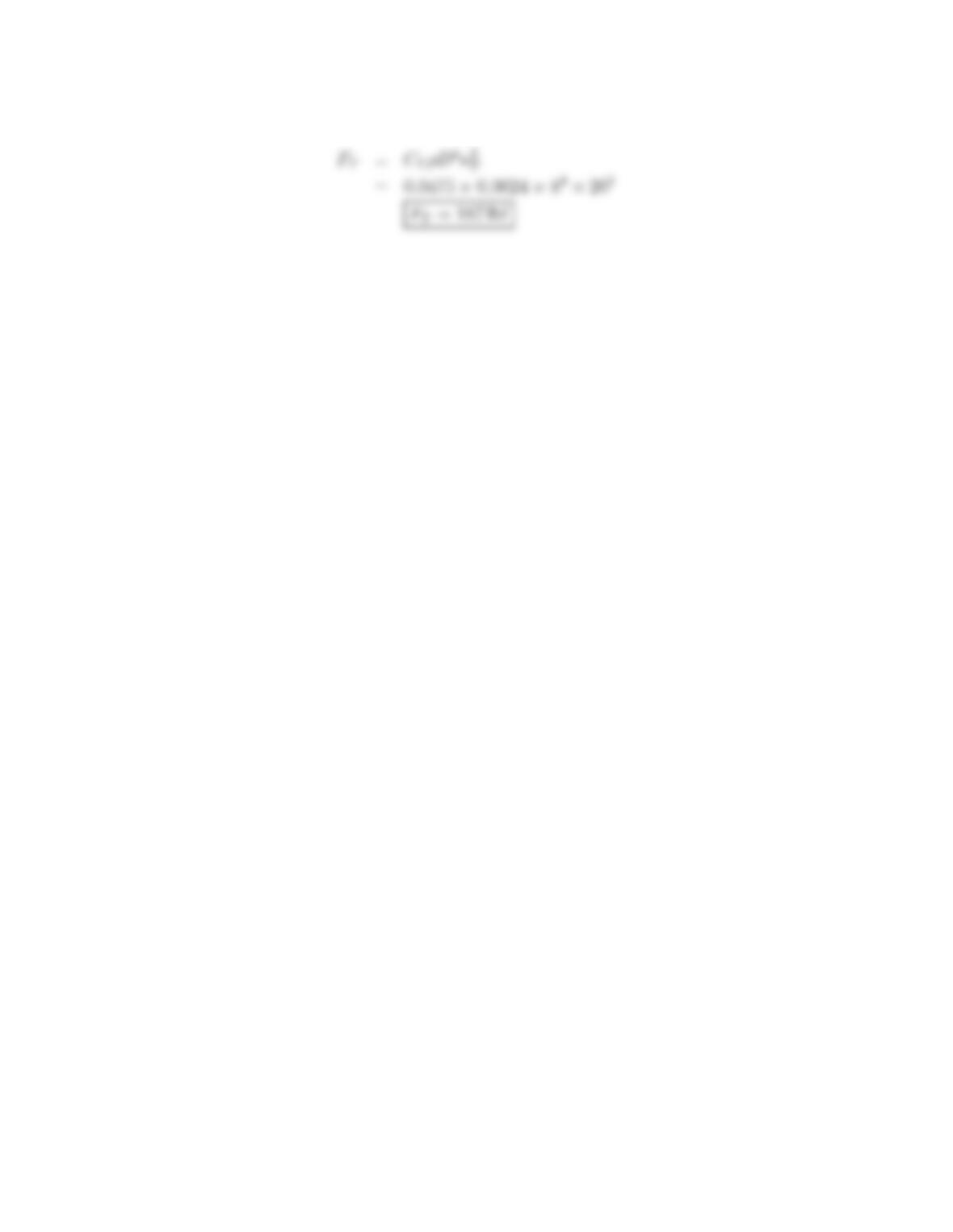
Propeller thrust force equation
6
14.6: PROBLEM DEFINITION
Situation: An 8 ft propeller on a swamp boat moving at 30 mph operates at maximum
efficiency.
Find: Angular speed of propeller.
PLAN
Use Fig 14.3 (EFM 10e) to find the advance diameter ratio at maximum efficiency.
SOLUTION
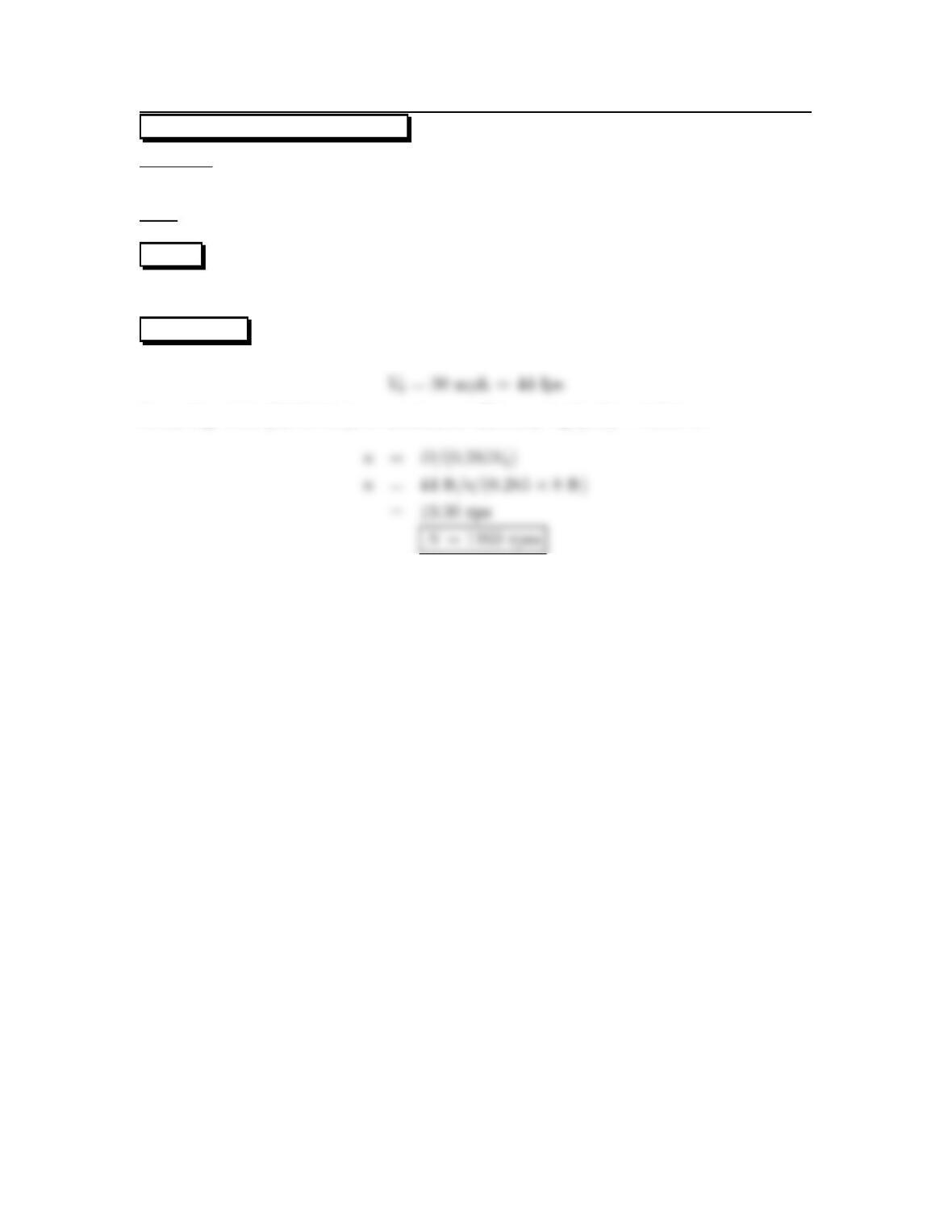
From Fig. 14.3 (EFM 10e), at maximum efficiency V0/(nD)=0.285 so
7
14.7: PROBLEM DEFINITION
Situation: An 8ft propeller on a swamp boat moving at 30 mph operates at maximum
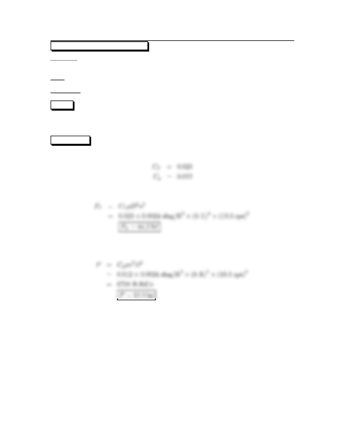
efficiency where rotational speed is 19.3 rps.
Find: (a) Thrust (b) Power output.
Properties:ρ=0.0024 slug/ft3.
PLAN
Apply the propeller thrust force equation and the propeller power equation. Use Fig
14.3 (EFM 10e) to find CTand CPat maximum efficiency.
SOLUTION
From Fig. 14.2
Propeller thrust force equation
Propeller power equation
8
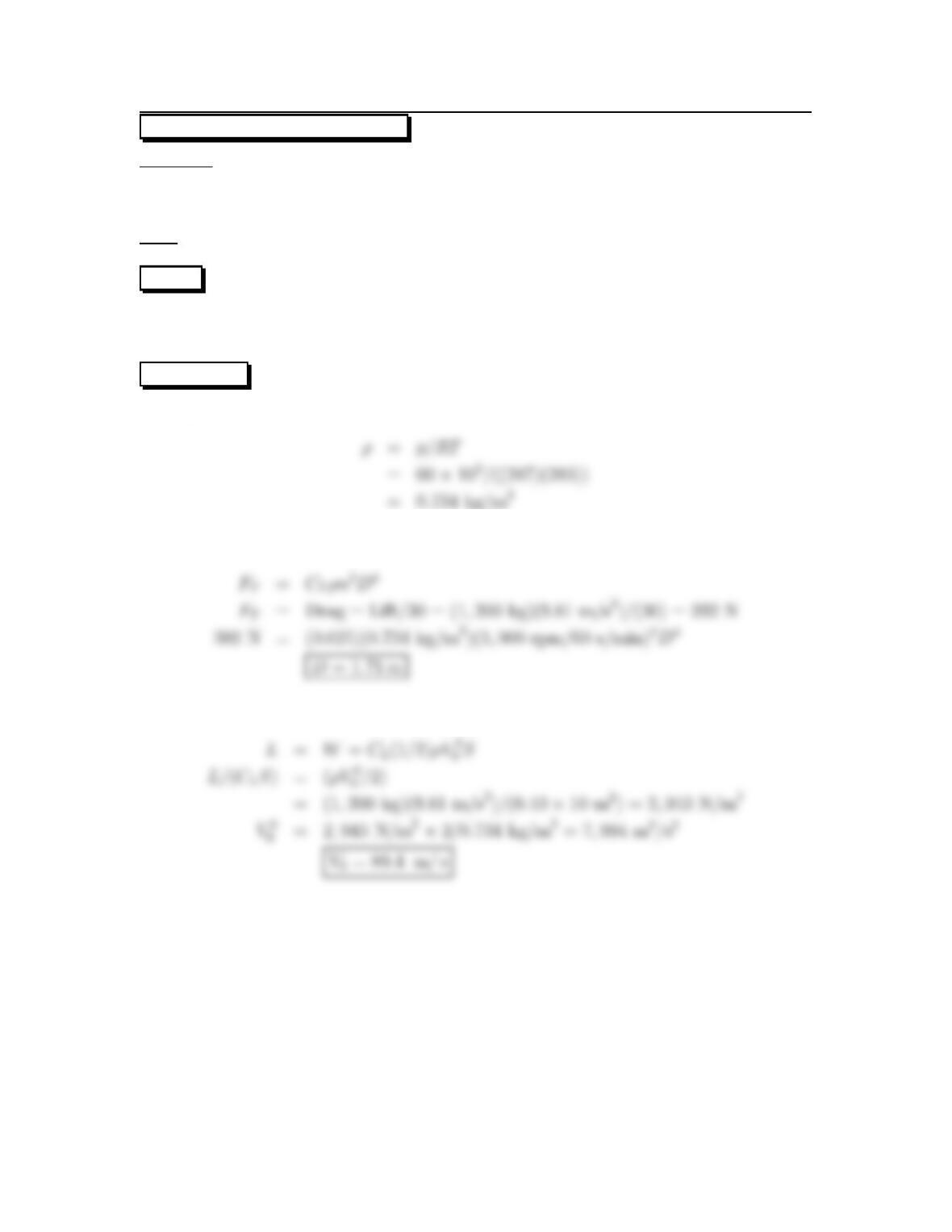
14.8: PROBLEM DEFINITION
Situation: A propeller is selected for an 1200 kg airplane operating at 60 kPa and
10oC. Lift to drag ratio of 30:1 with lift coefficient of 0.4 and plan form area of 10
m2. Engine rpm is 3000. At optimum efficiency thrust coefficient is 0.025.
Find: (a) Diameter of propeller (b) Speed of aircraft.
PLAN
Apply the Ideal gas law to get the density for the propeller thrust force equation to
calculate the diameter. Then apply the lift force equation to calculate the speed.
SOLUTION
Ideal gas law
Propeller thrust force equation
Lift force
9
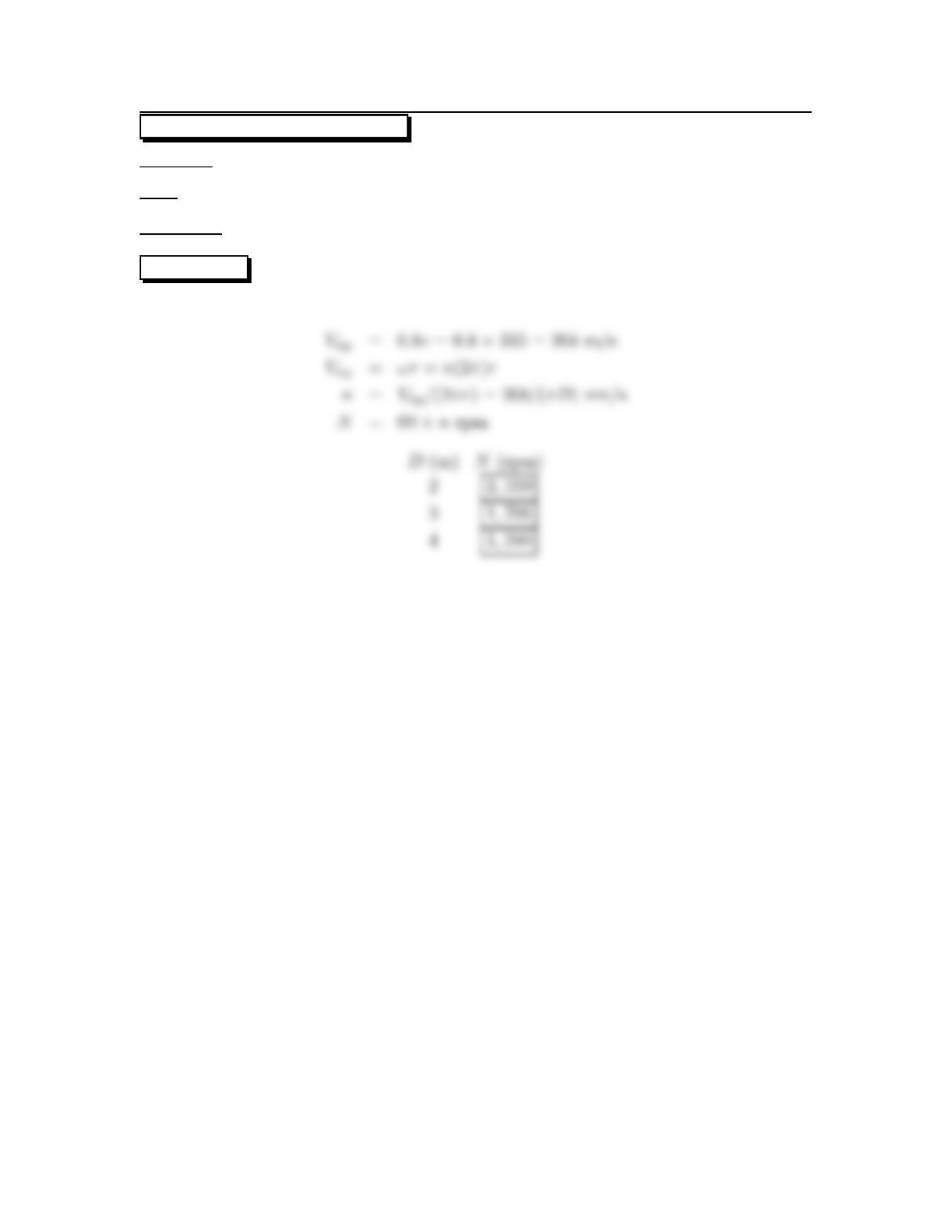
14.9: PROBLEM DEFINITION
Situation: A propeller tip speed must be less than 0.8 of sound speed.
Find: Maximum allowable angular speed for 2 m, 3 m and 4 m propeller.
Properties:c=335m/s
SOLUTION
10
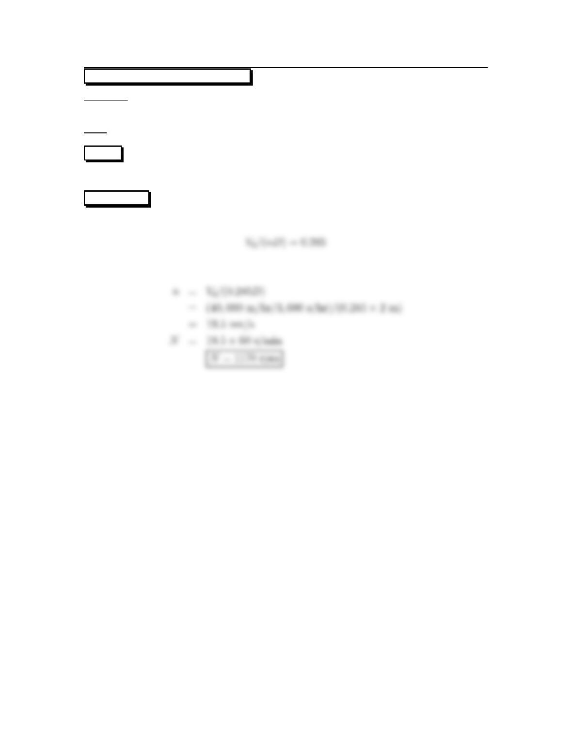
14.10: PROBLEM DEFINITION
Situation: A 2 m propeller used on a swamp boat moving at 40 km/hr and operates
at maximum efficiency.
Find: Angular speed of propeller.
PLAN
Use Fig 14.3 (EFM 10e) to find the advance diameter ratio at maximum efficiency.
SOLUTION
Advance ratio (from Fig. 14.3 (EFM 10e))
Rotation speed
11
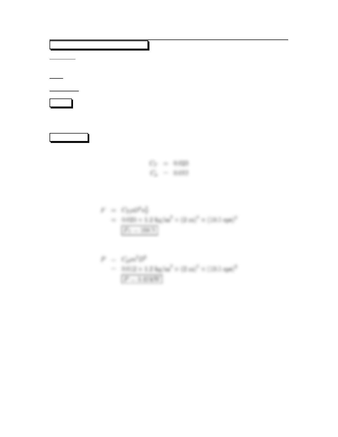
14.11: PROBLEM DEFINITION
Situation: A 2 m propeller used on a swamp boat moving at 40 km/hr and operates
at maximum efficiency. Rotational speed is 19.5 rps.
Find: (a) Thrust.(b) Power input.
Properties:ρ=1.2kg/m3.
PLAN
Apply the propeller thrust force equation and the propeller power equation. Use Fig
14.3 (EFM 10e) to find CTand CPat maximum efficiency.
SOLUTION
From Fig. 14.3 (EFM 10e),
Propeller thrust force equation
Propeller power equation
12
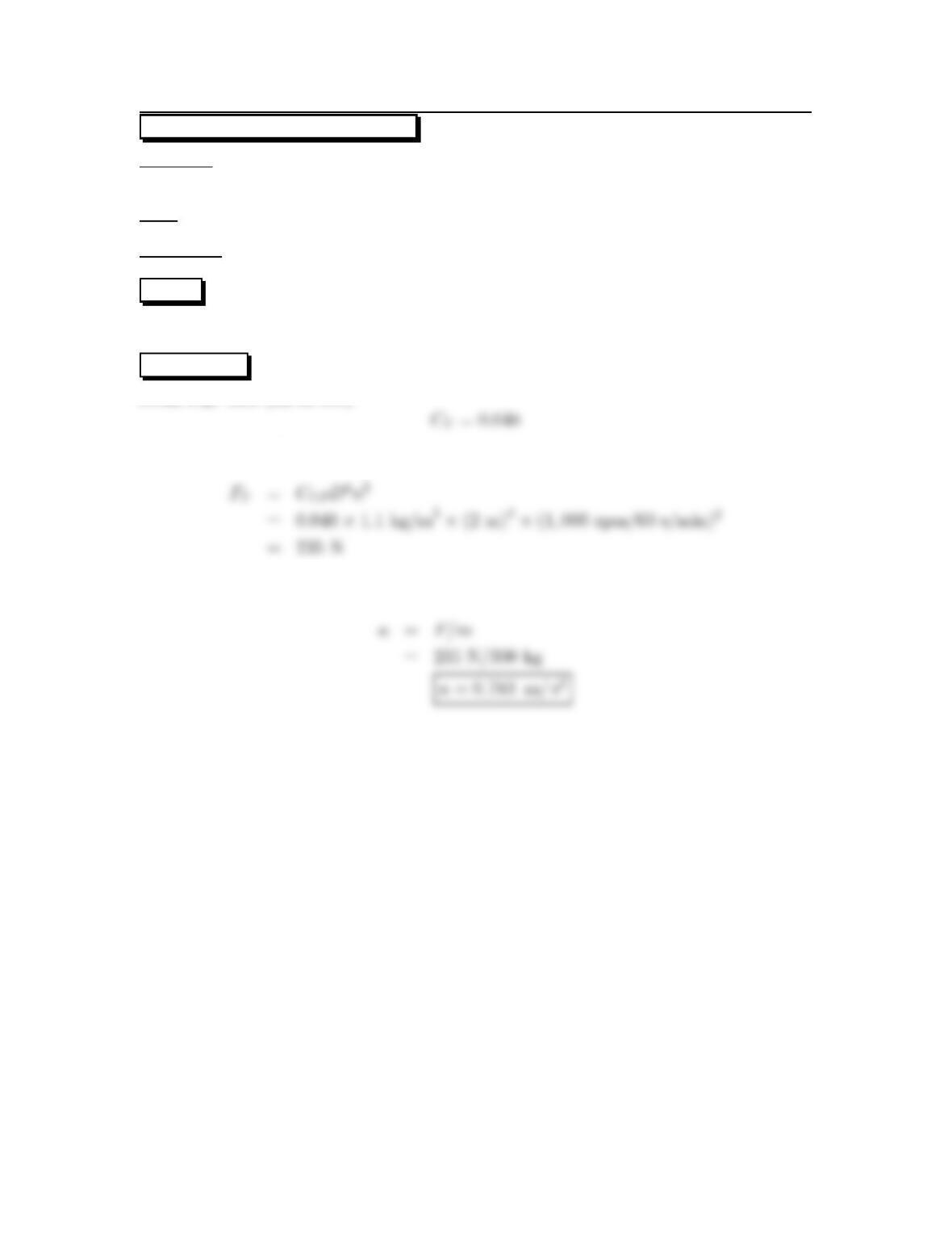
14.12: PROBLEM DEFINITION
Situation: A 2 m propeller used on swamp boat. Angular speed is 1000 rpm and
mass of boat and passengers is 300 kg.
Find: Initial acceleration.
Properties:ρ=1.1kg/m3.
PLAN
Apply the propeller thrust force equation. Use Fig 14.3 (EFM 10e) to find CT.
SOLUTION
From Fig. 14.3 (EFM 10e)
Propeller thrust force equation
Calculate acceleration
13
14.13: PROBLEM DEFINITION
Part (a)
Situation: Application of axial fans.
Find: Suited best for what conditions?
SOLUTION
The axial fan is best suited for high discharge, low head conditions.
Part (b)
Situation: Head produced and power required by axial pump.
Find: Variation of head produced and power required with discharge.
SOLUTION
14
14.14: PROBLEM DEFINITION
Situation: A 40 cm diameter pump operates at 1000 rpm against a 3 m head.
Find:Discharge.
PLAN
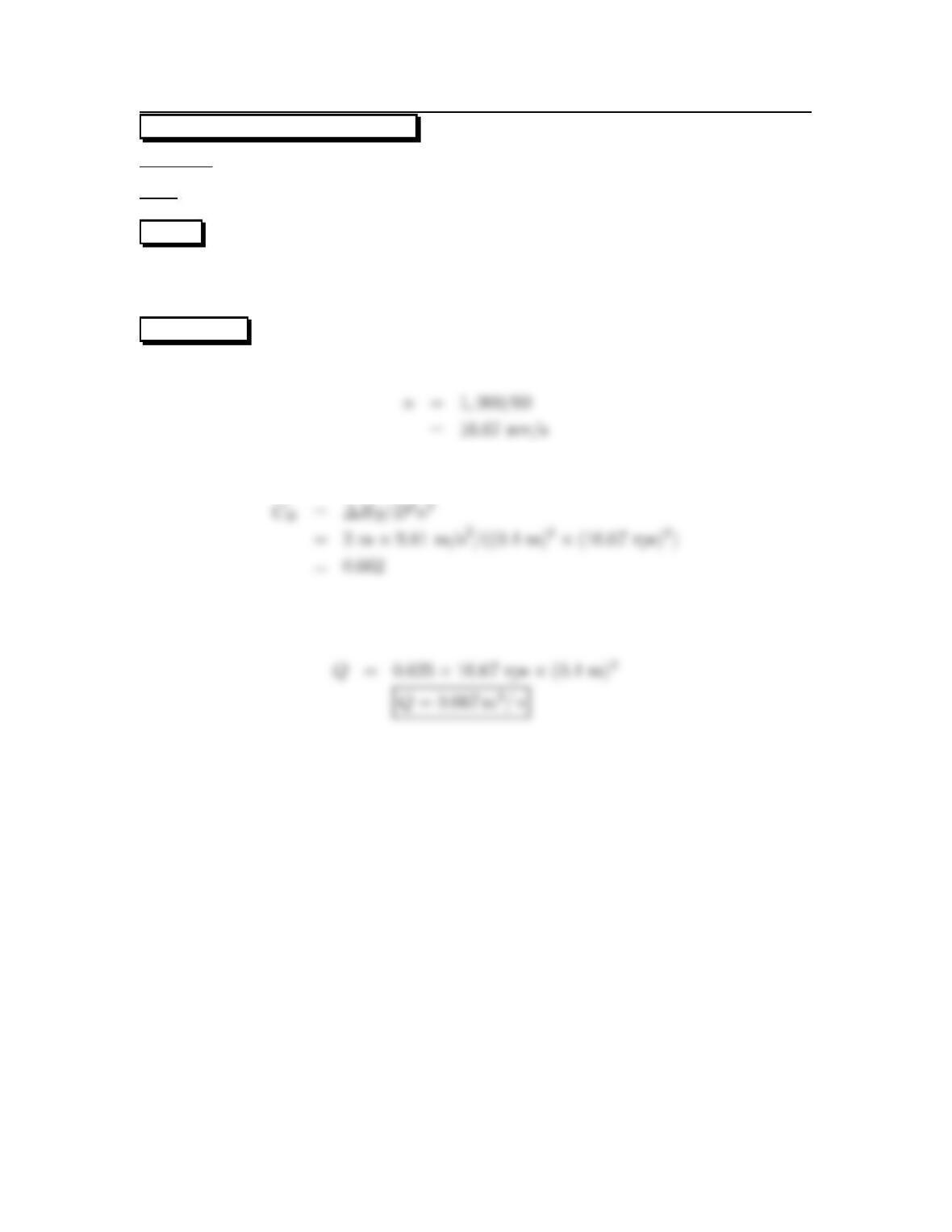
Apply discharge coefficient. Calculate the head coefficient to find the corresponding
discharge coefficient from Fig. 14.7 (EFM10e).
SOLUTION
Head coefficient
From Fig. 14.7 (EFM10e), CQ=Q/(nD3)=0.625.
Discharge coefficient
15
14.15: PROBLEM DEFINITION
Situation: A pump is used to pump water between two reservoirs.
Find: (a) Discharge (b) Power required.
PLAN
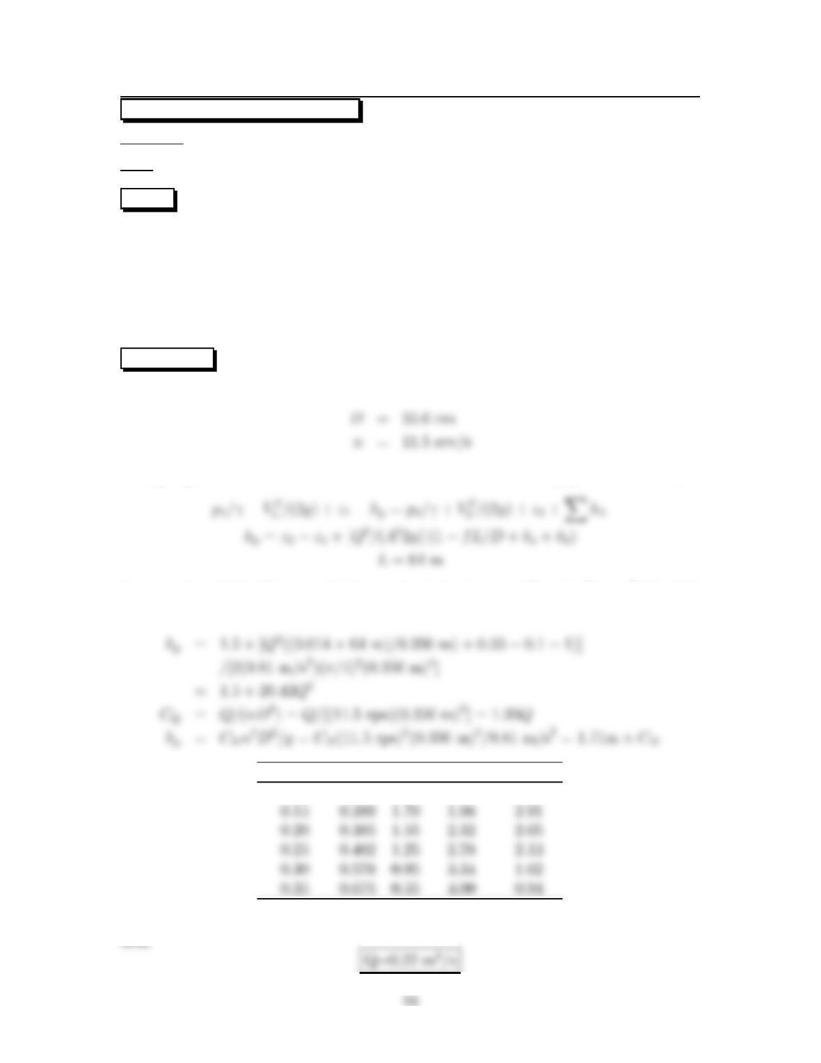
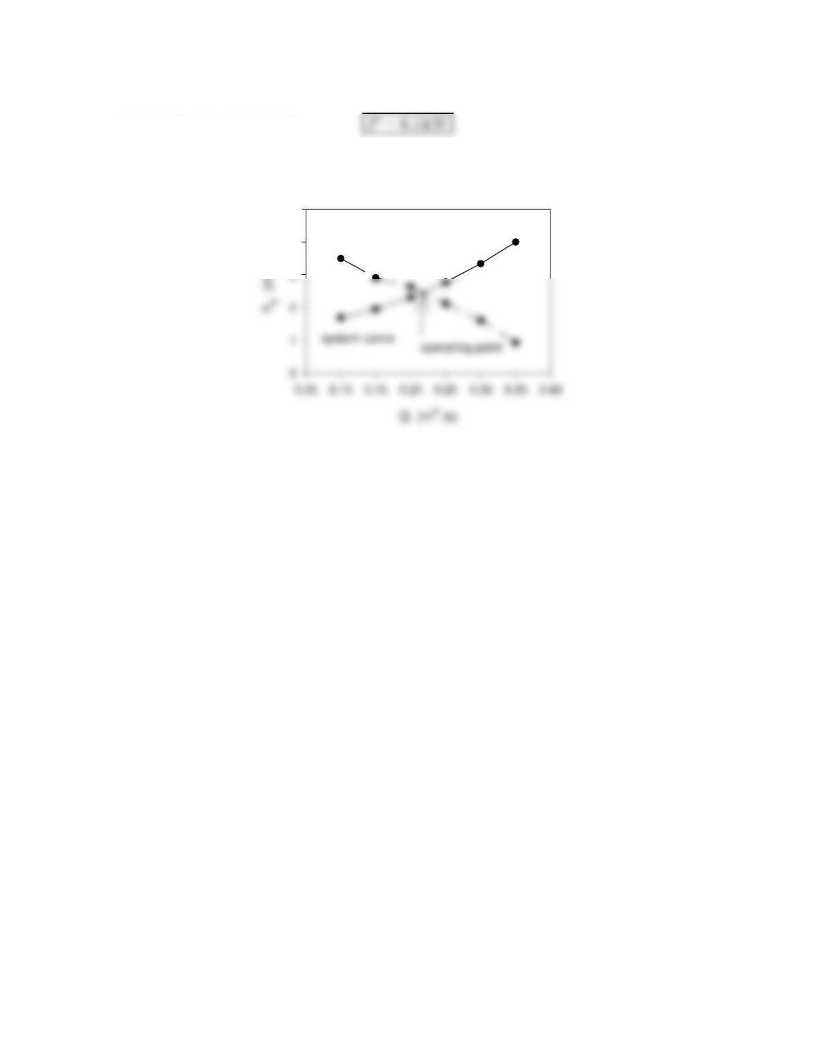
Plot the system curve and the pump curve. Apply the energy equation from the
reservoir surface to the center of the pipe at the outlet to solve the head of the pump
in terms of Q. Apply head coefficient to solve for the head of the pump in terms
of CH. Apply discharge coefficient to solve for CQin terms of Q—then use Figure
14.7 (EFM10e) to find the corresponding CH. Find the power by using Fig. 14.8
(EFM10e).
SOLUTION
Energy equation from the reservoir surface to the center of the pipe at the outlet,
Assume f=0.014 (for completely rough steel pipe),r
b/D =1.From Table 10.5
(EFM10e), kb=0.35,k
e=0.1
Q(m3/s)CQCHhp1(m)hp2(m)
0.10 0.193 2.05 1.70 3.50
Then plotting the system curve and the pump curve, we obtain the operating condi-
From Fig. 14.8 (EFM10e)
4
5
pump curve
17
14.16: PROBLEM DEFINITION
Situation: A pump is used to pump water between two reservoirs and rpm increased
to 900 rpm.
Find: (a) Discharge (b) Power required.
SOLUTION
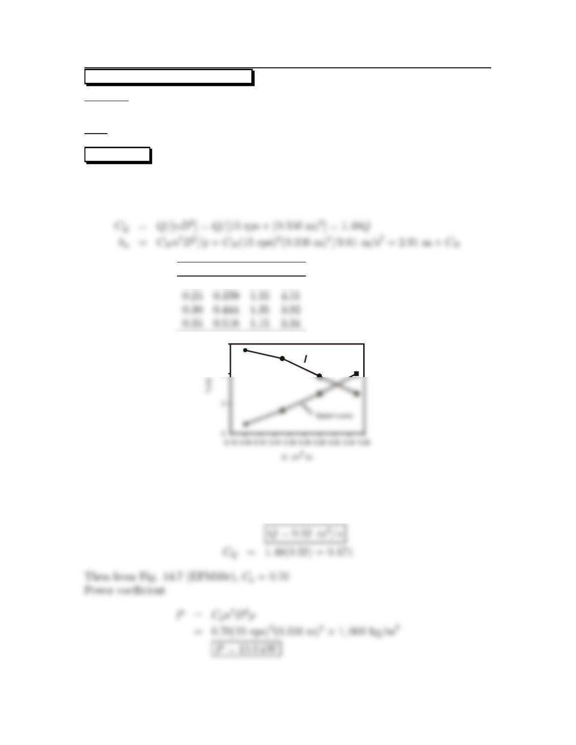
The system curve will be the same as in Prob. 14.15 (EFM 10e) but rotational rate
increased to 900 rpm/60 s/min=15 rps. Assume water density is 1000 kg/m3.
QC
QCHhp
0.20 0.296 1.65 4.79
4
5
Pump curve
Plotting the pump curve with the system curve gives the operating condition;
18
14.17: PROBLEM DEFINITION
Situation: A 20 inch pump operating at 1100 rpm is used at maximum efficiency.
Find: (a) Discharge.
(b) Head.
(c) Power required.
PLAN
Apply discharge, head, and power coefficients. Use Fig. 14.7 (EFM10e) to find the
discharge, power, and head coefficients at maximum efficiency. Assume density is
1.94 slug/ft3.
SOLUTION
From Fig. 14.7 (EFM10e) at maximum efficiency, CQ=0.64; Cp=0.60; and CH=
0.75
Discharge coefficient
Head coefficient
Power coefficient
19
14.18: PROBLEM DEFINITION
Situation: A 50 cm pump operates at maximum efficiency at 45 rps pumping water
at 10oC.
Find: (a) Discharge.
(b) Head.
(c) Power required.
Properties:FromTableA5ρ=1000kg/m3
PLAN
Apply discharge, head, and power coefficients. Use Fig. 14.7 (EFM10e) to find the
discharge, power, and head coefficients at maximum efficiency.
SOLUTION
At maximum efficiency, from Fig. 14.7 (EFM10e), CQ=0.64; Cp=0.60; CH=0.75
Discharge coefficient
Head coefficient
Power coefficient
20