14.19: PROBLEM DEFINITION
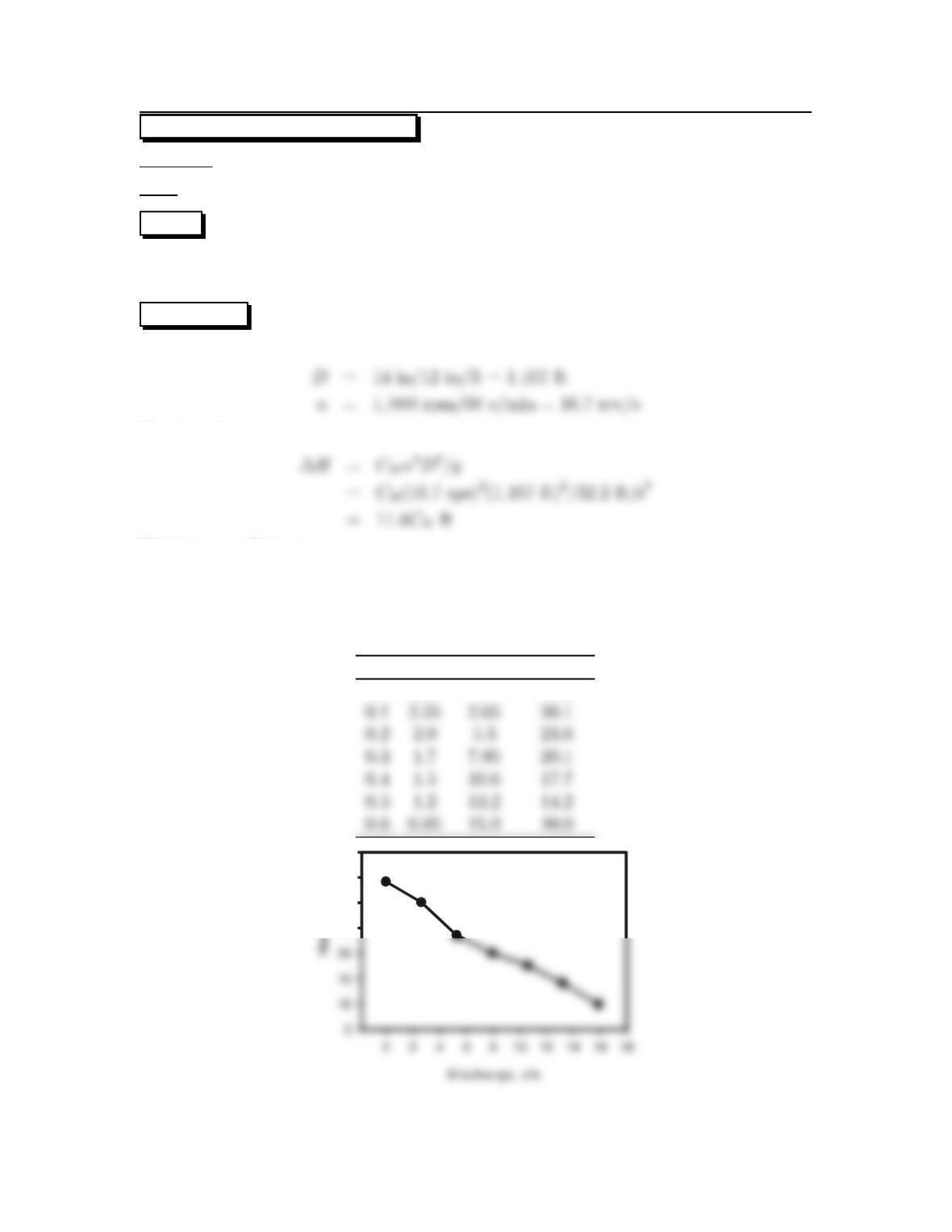
Situation: A 14 inch diameter pump operates at 1000 rpm.
Find: Plot the head-discharge curve.
PLAN
Apply the discharge and head coefficient equations at a series of coefficients corre-
sponding to each other from Fig. 14.7 (EFM10e).
SOLUTION
Head coefficient
Discharge coefficient
Q=CQnD3
=CQ16.7rps ×(1.167 ft)3
=26.5CQcfs
CQCHQ(cfs) ∆H(ft)
0.0 2.9 0 34.2
25
30
35
40
21
14.20: PROBLEM DEFINITION
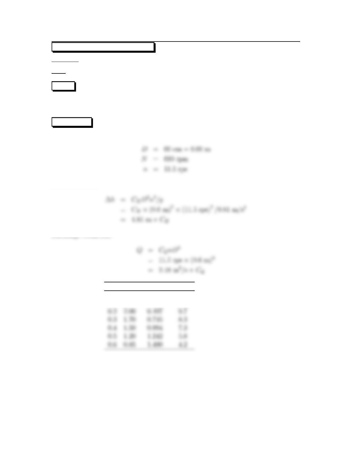
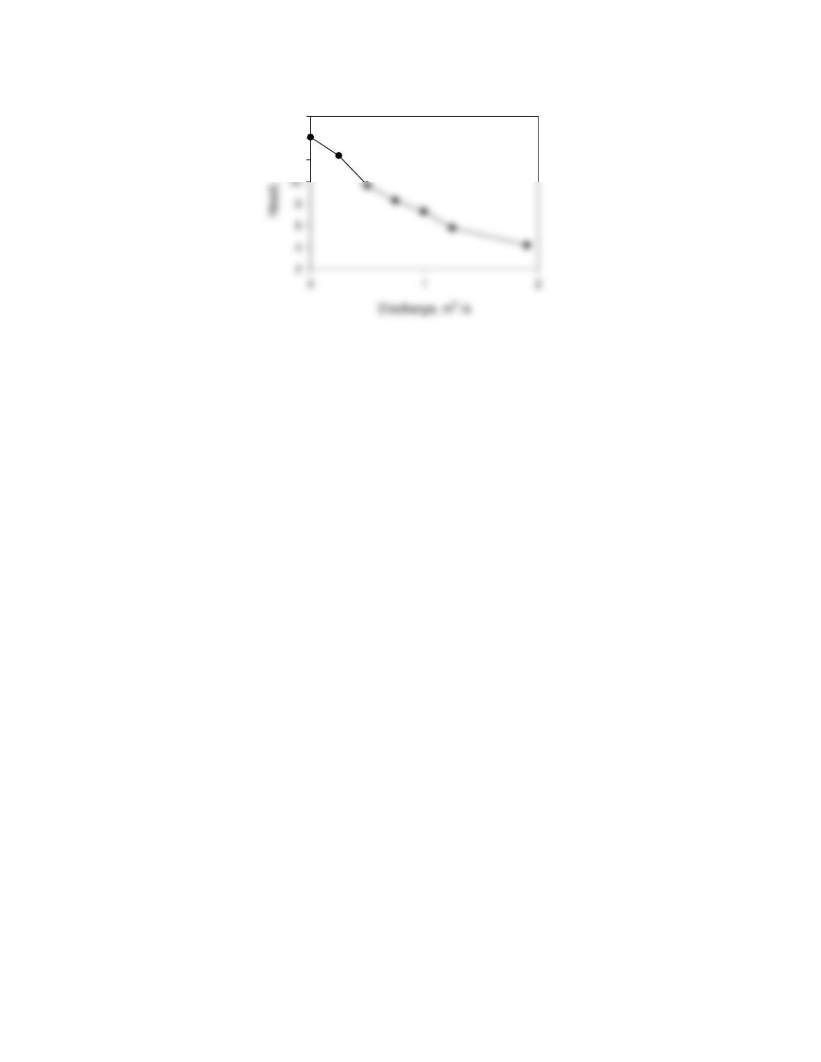
Situation: A 60 cm pump operates at 690 rpm.
Find: Plot the head-discharge curve.
PLAN
Apply the discharge and head coefficient equations at a series of coefficients corre-
sponding to each other from Fig. 14.7 (EFM10e).
SOLUTION
Head coefficient
Discharge coefficient
CQCHQ(m3/s) H(m)
0.0 2.90 0.0 14.1
0.1 2.55 0.248 12.4
22
12
14
16
23
14.21: PROBLEM DEFINITION
Situation: An axial blower for a 60 cm by 60 cm wind tunnel with velocity of 40 m/s.
Blower to operate at 2000 rpm.
Find: (a) Diameter.
(b) Power requirements.
Properties:ρ=1.2kg/m3
PLAN
Apply the discharge and power coefficient equations. Use Fig. 14.7 (EFM10e) to
find the discharge and head coefficients at maximum efficiency. Apply the flow rate
equation to get the Qto calculate the diameter with discharge coefficient.
SOLUTION
Flow rate equation
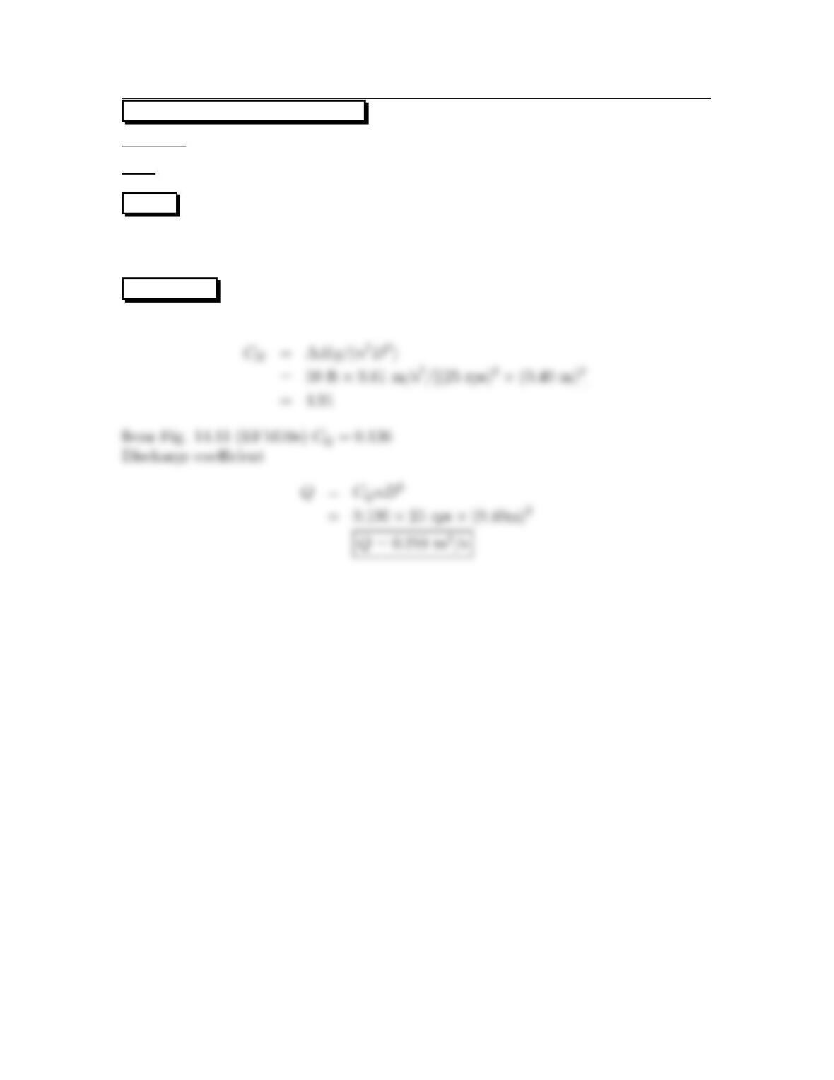
From Fig. 14.7 (EFM10e), at maximum efficiency, CQ=0.63 and Cp=0.60.Rotational
speed, n=2000 rpm
60 s/min =33.3rps
Discharge coefficient
Power coefficient
24
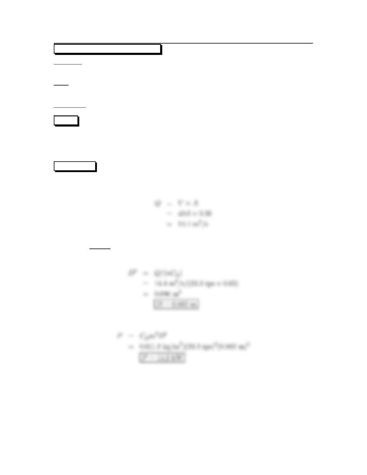
14.22: PROBLEM DEFINITION
Situation: A blower for air conditioning a 105m3building replacing air every 15 min.
Air temperature is 60oF. Blower operates at 600 rpm.
Find: (a) Diameter.
(b) Power requirements.
PLAN
Apply the discharge and power coefficient equations. Use Fig. 14.7 (EFM10e) to
find the discharge and head coefficients at maximum efficiency. Apply the flow rate
equation to get the Qto calculate the diameter with discharge coefficient.
SOLUTION
Discharge is
From Fig. 14.7 (EFM10e), at maximum efficiency, CQ=0.63; Cp=0.60
For two blowers operating in parallel, the discharge per blower will be one half so
Discharge coefficient
Power coefficient
25
14.23: PROBLEM DEFINITION
Situation: An 2 m axial fan used to run a 1.2 m diameter wind tunnel at 60 m/s.
Rotational speed of blower is 1800 rpm.
Find: Power needed to operate fan.
Properties:ρ=1.05 kg/m3
PLAN
Apply power coefficient. Calculate the discharge coefficient (apply the flow rate equa–
tion to find Q)tofind the corresponding power coefficient from Fig. 14.7 (EFM10e).
SOLUTION
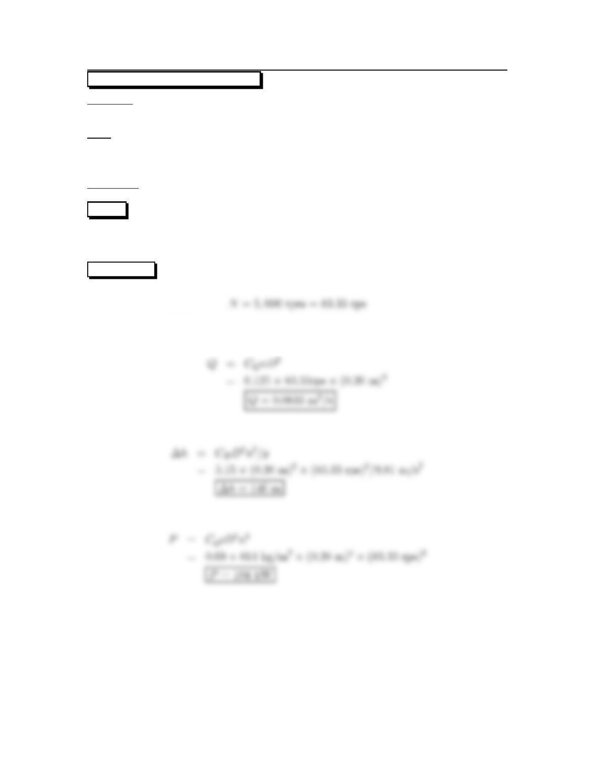
Flow rate equation
Discharge coefficient
From Fig. 14.7 (EFM10e) Cp=0.8.Then
Power coefficient
26

14.24: PROBLEM DEFINITION
Situation:Radialflow pumps
Find: Best conditions for operation.
SOLUTION
27

14.25: PROBLEM DEFINITION
Situation: Radial pump used to pump from reservoir.
Find: What limits depth of operation.
SOLUTION
The operational depth is limited by cavitation. In order to achieve flow the ;pressure
28
14.26: PROBLEM DEFINITION
Situation: A pump is doubled in size and halved in speed.
Find: (a)Head at maximum efficiency.
(b) Discharge at maximum efficiency.
PLAN
Apply discharge and head coefficients. Use Fig. 14.11 (EFM 10e) to find the discharge
andheadcoefficients at maximum efficiency.
SOLUTION
D=0.371 m×2=0.742 m
n=2,133.5rpm/(2 ×60 s/min)=17.77 rps
From Fig. 14.11 (EFM 10e), at peak efficiency CQ=0.121,C
H=5.15.
Head coefficient
29
14.27: PROBLEM DEFINITION
Situation: A pump for water from 366 m elevation to 450 m elevation through 610 m
of 36 cm steel pipe.
Find: Discharge through pipe.
Properties:FromTableA5,ρ=998kg/m3,ν=10
−6m2/s
PLAN
Guess the pump head and iterate using Fig. 14.10 (EFM10e) to get the corresponding
flow rate and the Reynolds number. Find the Darcy-Weisbach friction factor to
determine frictional loss in the pipe. Then write the energy equation between the two
reservoirs and generate the system curve. The operating point is where the system
andpumpcurveintersect.
SOLUTION
Assume ∆h=90m(>∆z),then from Fig. 14.10 (EFM10e), Q=0.24 m3/s
Flow rate equation
Reynolds number
Frictional head loss. For steel pipe, ks=0.046 mm from Table 10.4 (EFM 10e). Thus
ks/D =0.046 mm/360 mm=1.2×10⁻⁴.From Fig. 10.14 (EFM10e), f=0.014
Writing the energy equation between the two reservoirs
30
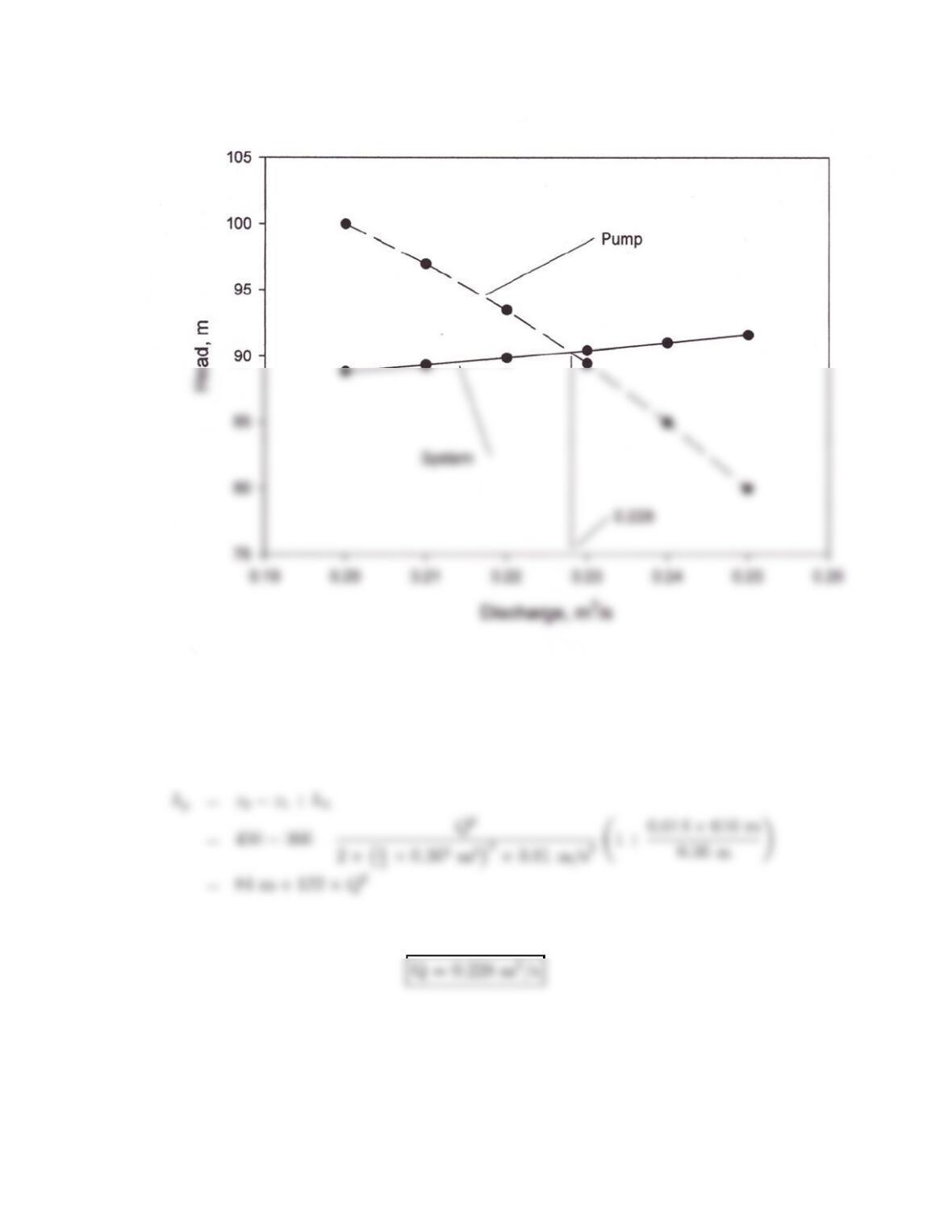
Figure 1:
The system curve is
Plotting pump and system curve
31
14.28: PROBLEM DEFINITION
Situation: A pump operated at 1600 rpm.
Find: Discharge when head is 135 ft.
PLAN
Apply discharge coefficient. Calculate the head coefficient to find the corresponding
discharge coefficient from Fig. 14.11 (EFM10e).
SOLUTION
Head coefficient
from Fig. 14.11 (EFM10e)
Discharge coefficient
32
14.29: PROBLEM DEFINITION
Situation: A pump operating at 1600 rpm.
Find: Maximum possible head developed.
PLAN
Apply head coefficient.
SOLUTION
Since CHwill be the same for the maximum head condition, then
33
14.30: PROBLEM DEFINITION
Situation: A pump operated at 30 rps.
Find:Shutoffhead.
PLAN
Apply head coefficient.
SOLUTION
so
H30/H35.6=(30/35.6)2
or
34
14.31: PROBLEM DEFINITION
Situation: A 40 cm diameter pump operated at 25 rps.
Find: Discharge when head is 50 m.
PLAN
Apply discharge coefficient. Calculate the head coefficient to find the corresponding
discharge coefficient from Fig. 14.11 (EFM10e).
SOLUTION
Head coefficient
35
14.32: PROBLEM DEFINITION
Situation: A 20 cm pump for kerosene operates at 5000 rpm. is described in the
problem statement.
Find:(a)Flowrate.
(b) Pressure rise across pump.
(c) Power required.
Properties:FromTableA.4ρ=814kg/m3.
PLAN
Apply the discharge, head, and power coefficient equations. Use Fig. 14.11 (EFM10e)
to find the discharge, power, and head coefficients at maximum efficiency.
SOLUTION
From Fig. 14.11 (EFM10e) at maximum efficiency CQ=0.125; CH=5.15; Cp=0.69
Discharge coefficient
Head coefficient
Power coefficient
36
14.33: PROBLEM DEFINITION
Part (a)
Find:Difference between system and pump curves.
SOLUTION
The pump curve provides the head supplied by the pump while the system curve is
the head required to operate the system.
Part (b)
Find:Define the operating point.
SOLUTION
37

14.34: PROBLEM DEFINITION
Situation:Significance of specific speed.
Find: The best pump corresponding to high specificspeed.
SOLUTION
38
14.35: PROBLEM DEFINITION
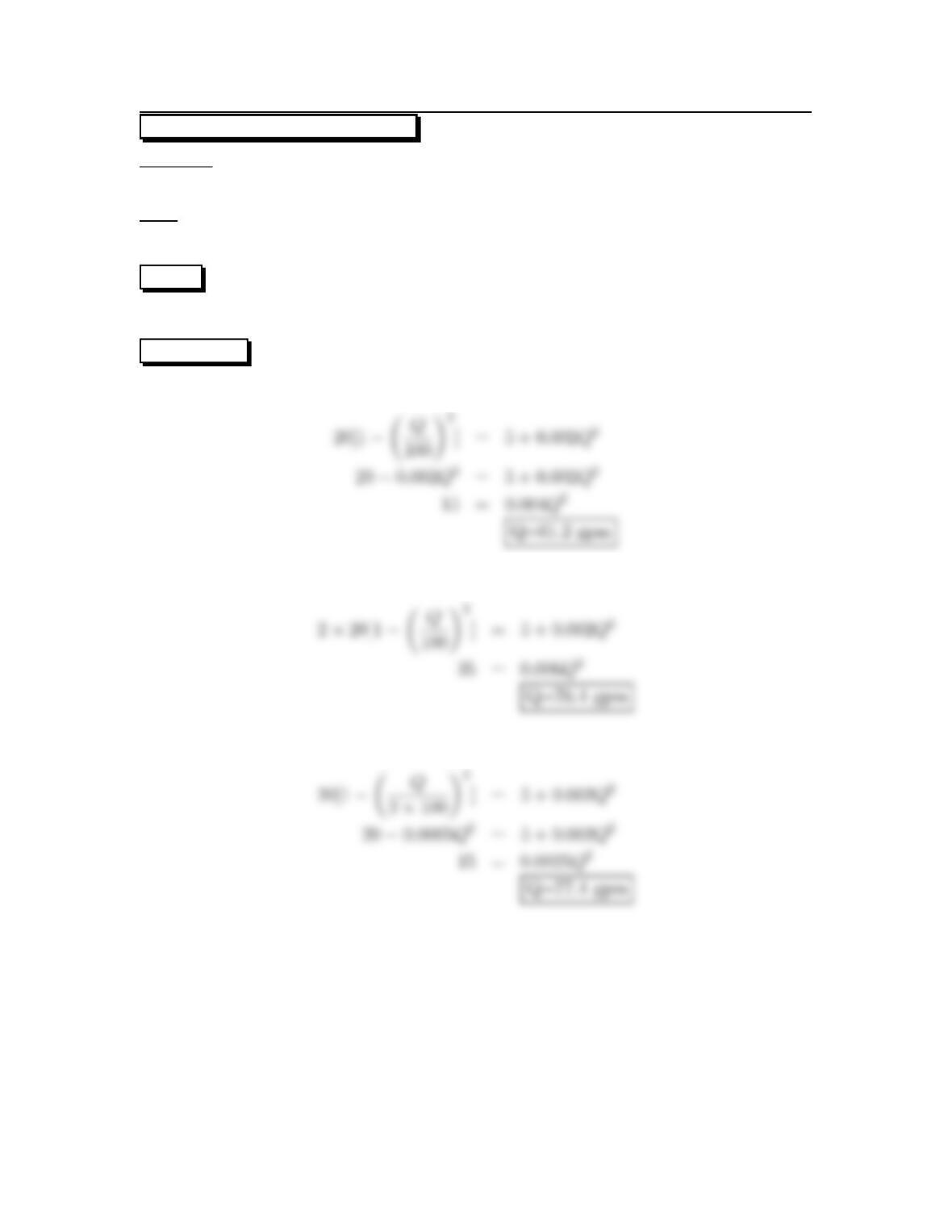
Situation: Pumps, with characteristics hp,pump =20[1−(Q/100)2]are connected in
series and parallel to operate a fluid system with system curve hp,sys =5+0.002Q2.
Find: Operating point with a) one pump, b) two pumps connected in series and c)
two pumps connected in parallel.
PLAN
Equate the head provided by the pump and the head required by the system.
SOLUTION
a) For one pump
b) For two pumps in series
c) For two pumps in parallel
39
14.36: PROBLEM DEFINITION
Situation: The pump is described in Problem 14.15 (EFM10e) has a rotational speed
of 690 rpm, a discharge of 0.22 m3/s and pipe diameter of 35.6 cm.
Find: (a) Suction specificspeed.
(b) Safety of operation with respect to cavitation.
Properties:FromTableA.5(EFM10e),pv(10oC)=1230 Pa,
PLAN
Calculate the pressure at the NSPH at the pump inlet and the suction specificspeed.
Then compare that with the critical value of 85,000.
SOLUTION
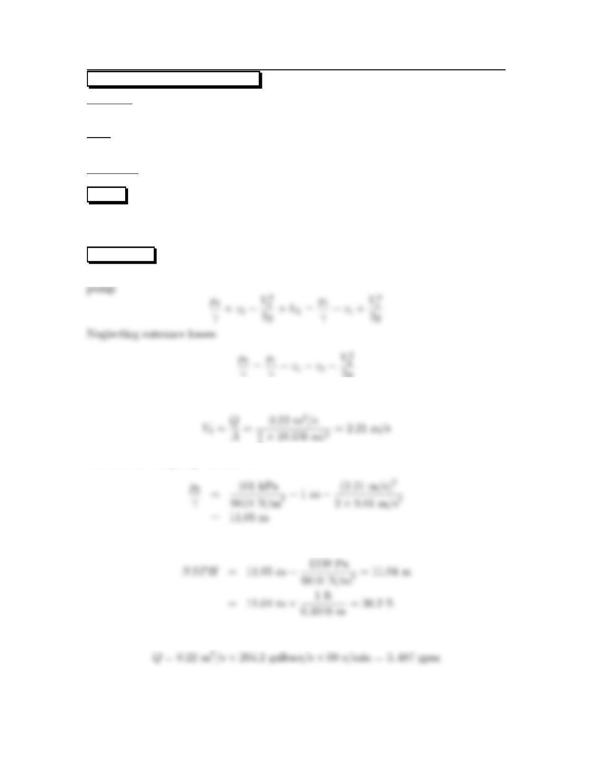
From the energy equation, where point 1 is water surface and point 2 is entrance to
γ=p1
γ+z1−z2−V2
2g
The velocity at pump
4×(0.356 m)2=2.21 m/s
The head at the pump entrance is
The NSPH is
The discharge in gpm
40