PROBLEM 13.42
KNOWN: Emissivities, diameters and temperatures of concentric spheres.
FIND: (a) Radiation transfer rate for black surfaces. (b) Radiation transfer rate for diffuse–gray
surfaces, (c) Effects of increasing the diameter and assuming blackbody behavior for the outer sphere.
(d) Effect of emissivities on net radiation exchange.
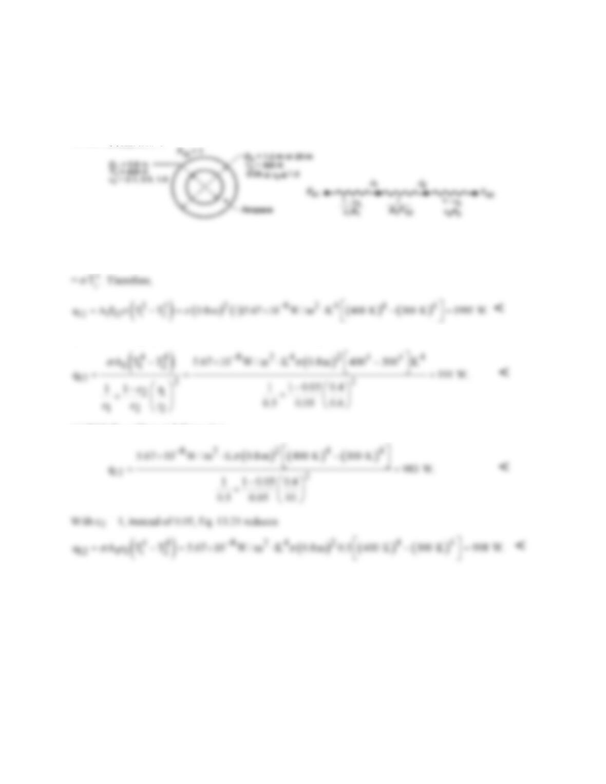
SCHEMATIC:
ASSUMPTIONS: (1) Blackbody or diffuse-gray surface behavior.
ANALYSIS: (a) Assuming blackbody behavior, it follows that qij = AiFij(Ji – Jj) where Ji = σ
4
i
T
and Jj
(b) For diffuse–gray surface behavior, it follows from Eq. 13.26
(c) With D2 = 20 m, it follows that
Continued …
PROBLEM 13.42 (Cont.)
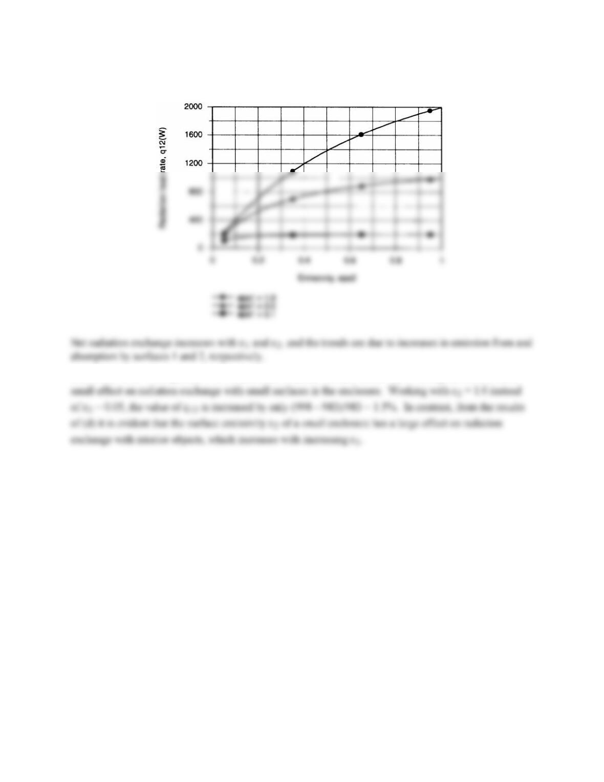
(d) Using the IHT Radiation Tool Pad, the following results were obtained
COMMENTS: From part (c) it is evident that the actual surface emissivity of a large enclosure has a
PROBLEM 13.43
KNOWN: Surface emissivities of a radiation shield inserted between parallel plates of prescribed
temperatures and emissivities.
FIND: (a) Effect of shield orientation on radiation transfer, (b) Effect of shield orientation on shield
temperature.
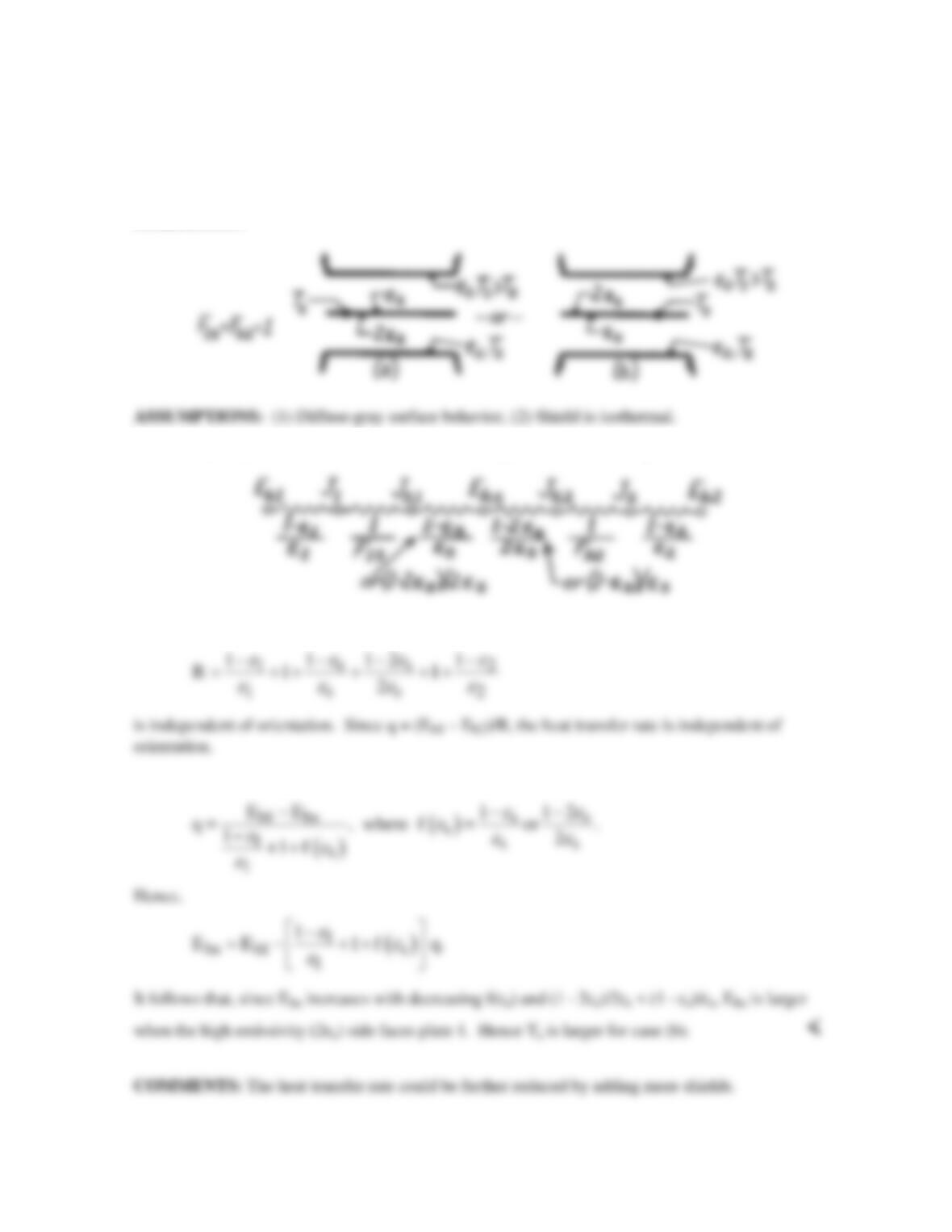
SCHEMATIC:
ANALYSIS: (a) On a unit area basis, the network representation of the system is
Hence the total radiation resistance,
(b) Considering that portion of the circuit between Eb1 and Ebs, it follows that
PROBLEM 13.44
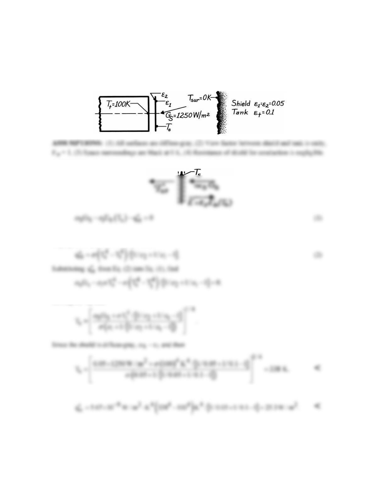
KNOWN: End of propellant tank with radiation shield is subjected to solar irradiation in space
environment.
FIND: (a) Temperature of the shield, Ts, and (b) Heat flux to the tank,
()
2
1
q W/m .
′′
SCHEMATIC:
ANALYSIS: (a) Perform a radiation balance on the shield. From the schematic,
where
st
q′′
is the net heat exchange between the shield and the tank. Considering these two surfaces as
large, parallel planes, from Eq. 13.24,
Solving for Ts, find
(b) The heat flux to the tank can be determined from Eq. (2),
COMMENTS: The heat flux could be further reduced by adding more shields.
PROBLEM 13.45
KNOWN: Black panel at 77 K in large vacuum chamber at 300 K with radiation shield having ε =
0.05.
FIND: Net rate of heat transfer by radiation to the panel.
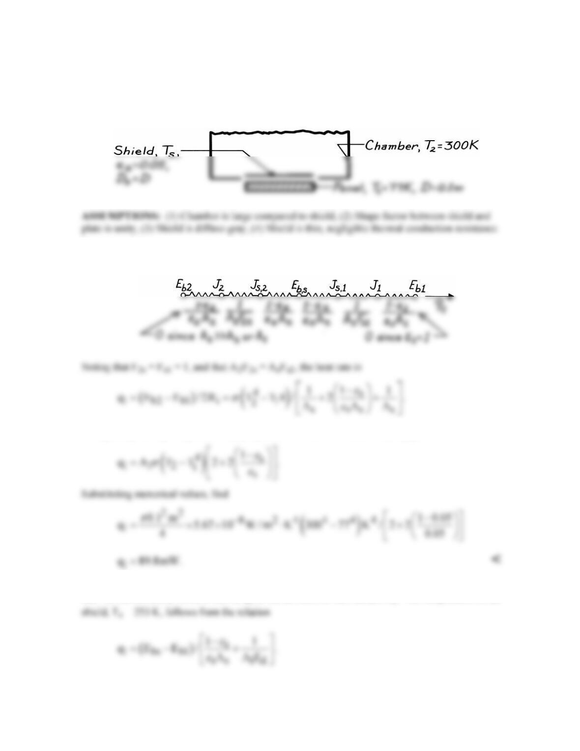
SCHEMATIC:
ANALYSIS: The arrangement lends itself to a network representation following Figs. 13.10 and
13.11.
Recognizing that As = A1 and multiplying numerator and denominator by A1 gives
COMMENTS: (1) In using the network representation, be sure to designate direction of the net heat
rate. In this situation, we have shown q1 as the net rate into the surface A1. The temperature of the
PROBLEM 13.46
KNOWN: Dense cryogenic piping array located close to furnace wall.
FIND: Number of radiation shields, N, to be installed such that the temperature of the shield closest
to the array, Ts,N, is less than 30°C.
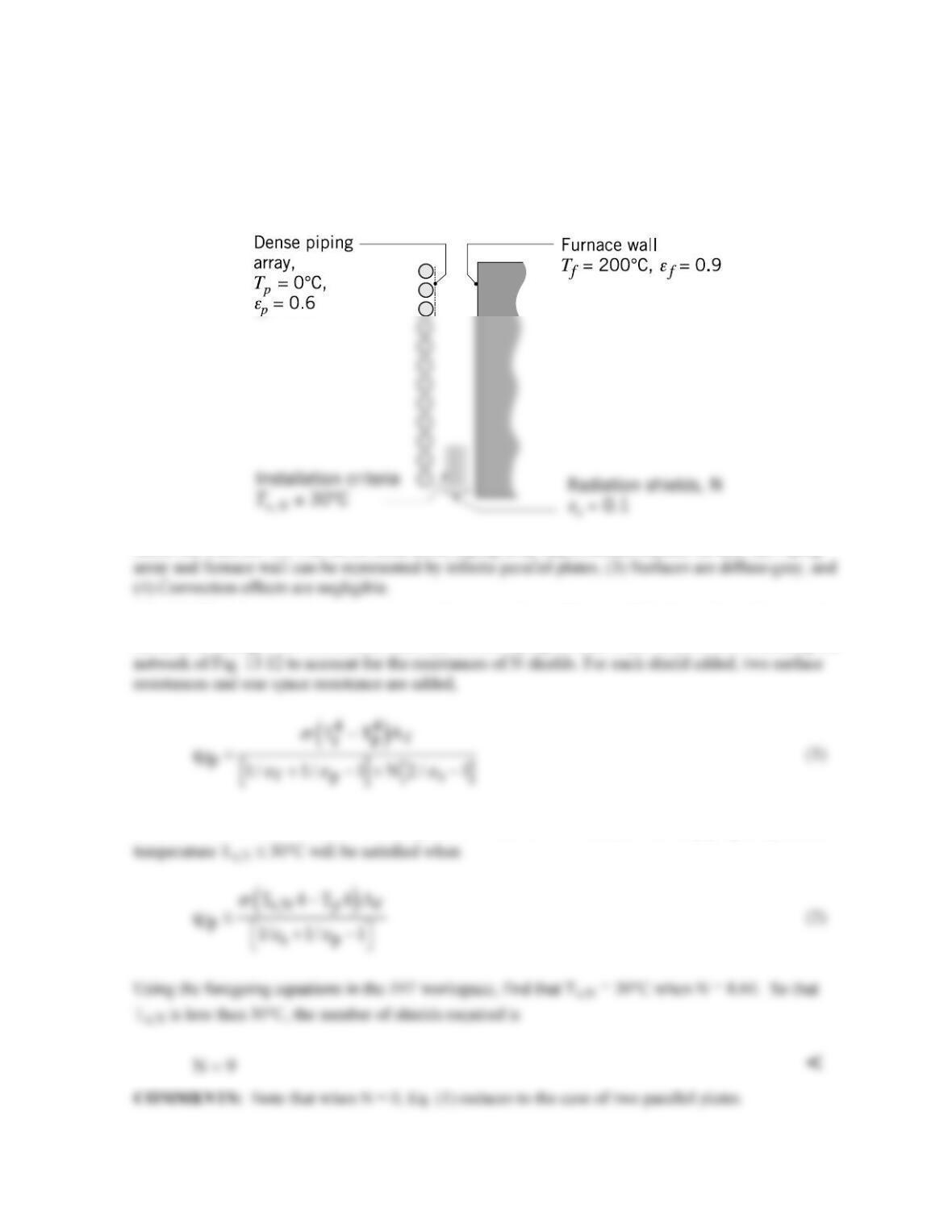
SCHEMATIC:
ASSUMPTIONS: (1) The ice-covered dense piping array approximates a plane surface, (2) Piping
ANALYSIS: Treating the piping array and furnace wall as infinite parallel plates, the net heat rate by
radiation exchange with N shields of identical emissivity, εs, on both sides follows from extending the
where σ = 5.67 × 10⁻⁸ W/m2⋅K4. The requirement that the Nth shield (next to the piping array) has a
PROBLEM 13.47
KNOWN: Concentric tube arrangement with diffuse-gray surfaces.
FIND: (a) Rate of heatt gain by the cryogenic fluid per unit length of the inner tube (W/m), (b)
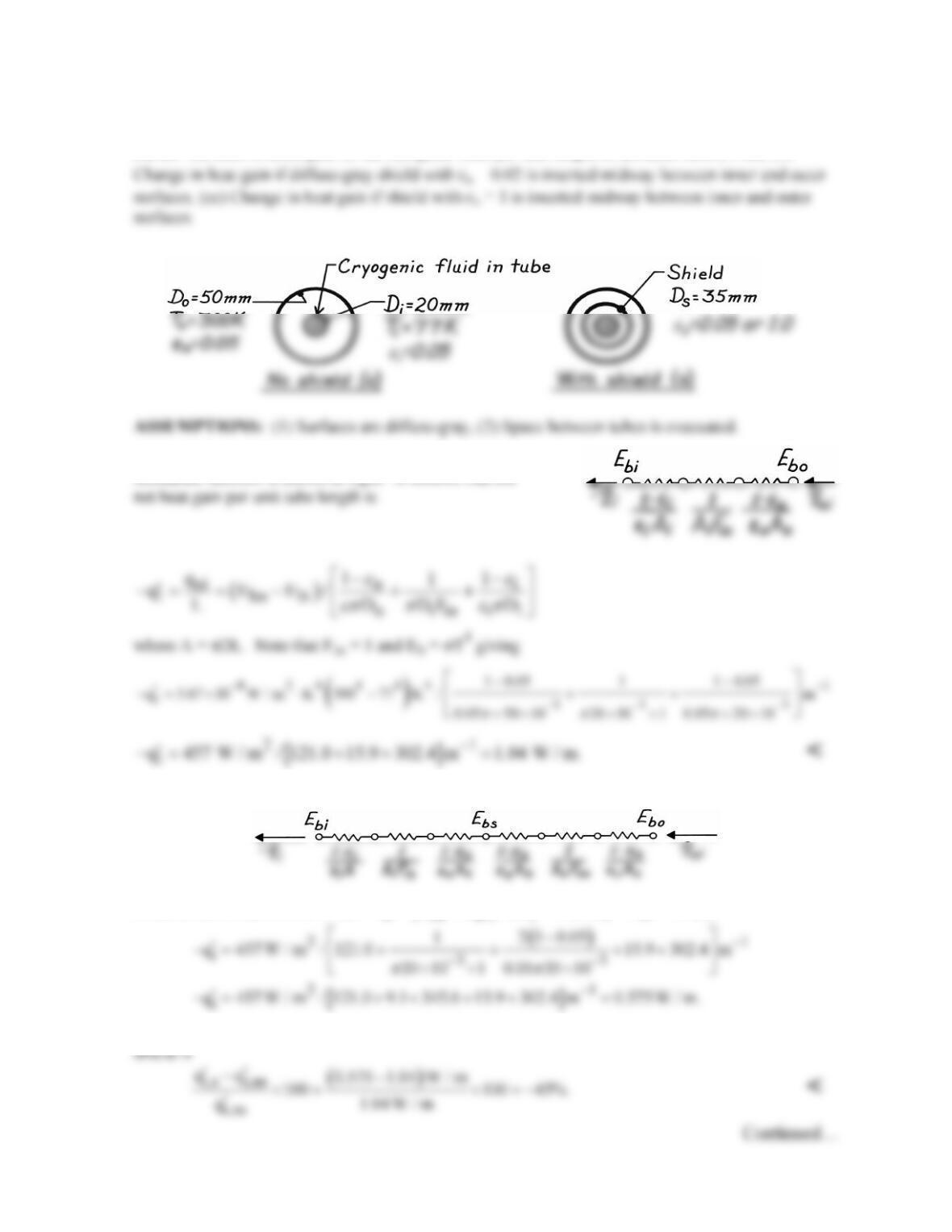
SCHEMATIC:
ANALYSIS: (a) For the no shield case, the radiation
resistance network is shown at right. It follows that the
(b) For the with shield case, the thermal circuit will include three additional resistances.
From the network, it follows that
( )
i bo bi t
q E E / R.−= − Σ
With Fis = Fso = 1, find
The change (percentage) in heat gain per unit length of the tube as a result of inserting the radiation
PROBLEM 13.47 (Cont.)
(c) Repeating the calculation for εs = 1 yields
i
q 0.98 W / m.
′
−=
The change (percentage) in heat gain
PROBLEM 13.48
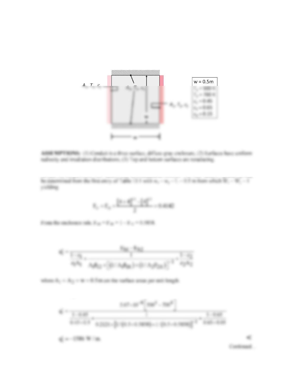
KNOWN: Long conduit of known dimensions and surface emissivities. Hot and cold conduit wall
temperatures.
FIND: Temperature of insulated walls and net radiation heat rate from surface 2 per unit conduit
length.
SCHEMATIC:
ANALYSIS: Treating the top and bottom surfaces as one reradiating surface (designated below as
surface R), the pertinent view factors may be evaluated as follows. The view factors F12 and F21 may
From Equation 13.30, the net radiant power for wall 1 per unit length is
Hence, with
4
b
E T,
σ
=
PROBLEM 13.48 (Cont.)
By conservation of energy,
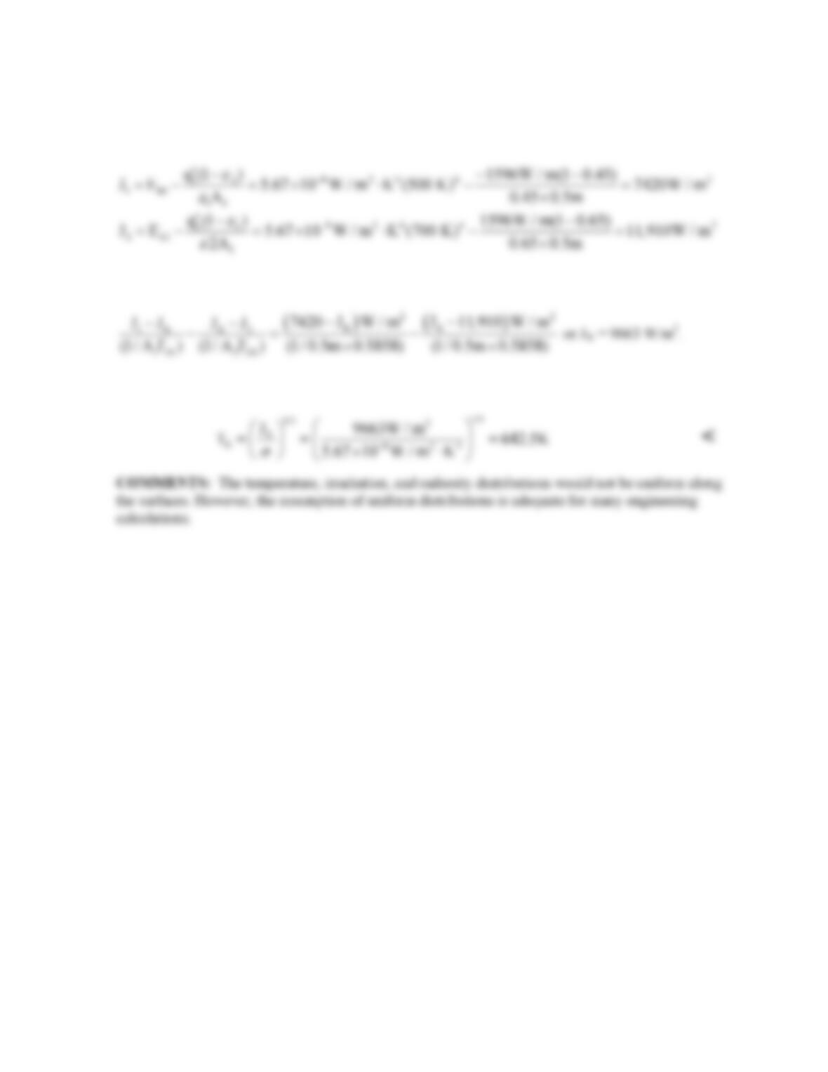
2
q 1586 W / m.
′=
We may calculate the radiosities from Equation 13.19
as follows.
From Equation 13.31, the radiosity of the reradiating surface may be found from
The temperature of the reradiating surface is then
PROBLEM 13.49
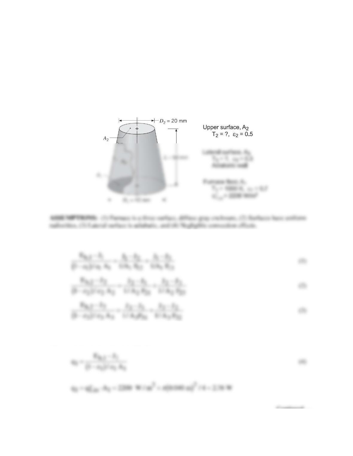
KNOWN: Furnace in the form of a truncated conical section, floor (1) maintained at T1 = 1000 K by
providing a heat flux
′′ =q W / m ;
1,in 2
2200
lateral wall (3) perfectly insulated; radiative properties
of all surfaces specified.
FIND: (a) Temperature of the upper surface, T2, and of the lateral wall T3, and (b) T2 and T3 if all
the furnace surfaces are black instead of diffuse–gray, with all other conditions remain unchanged.
Explain effect of ε2 on your results.
SCHEMATIC:
ANALYSIS: For the three-surface enclosure, write the radiation surface energy balances, Eq. 13.21,
to find the radiosities of the three surfaces.
where the blackbody emissive powers are of the form Eb = σ T4 with σ = 5.67 × 10⁻⁸ W/m2⋅K4. From
Eq. 13.19, the net radiation leaving A1 is
Continued …
PROBLEM 13.49 (Cont.)
Since the lateral surface is adiabatic,
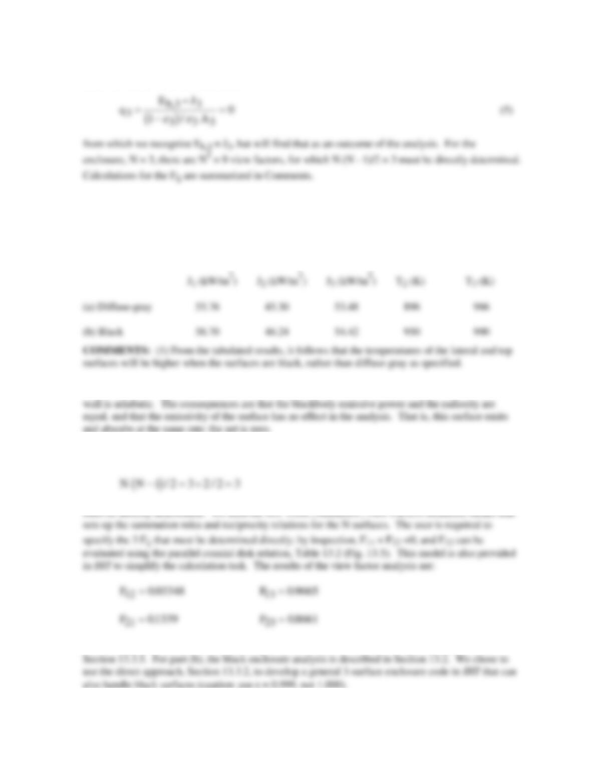
With the foregoing five relations, we can determine the five unknowns: J1, J2, J3, Eb,2, and Eb,3. The
temperatures T2 and T3 will be evaluated from the relation Eb = σ T4. Using this analysis approach
with the relations in the IHT workspace, the results for (a) the diffuse–gray surfaces and (b) black
surfaces are tabulated below. <
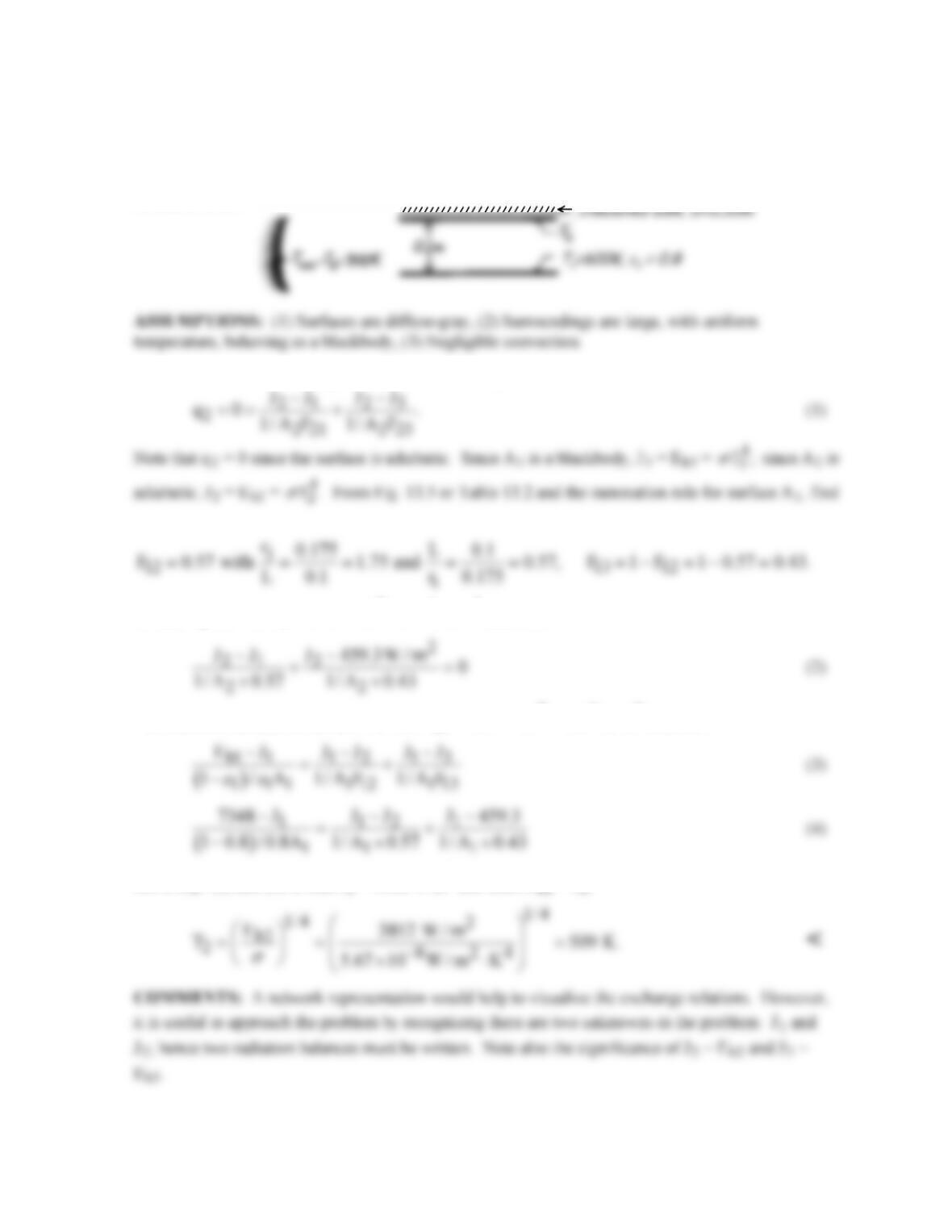
(2) From Eq. (5) for the net heat radiation leaving the lateral surface, A3, the rate is zero since the
(3) For the enclosure, N = 3, there are N2 = 9 view factors, for which
(4) An alternative method of solution for part (a) is to treat the enclosure of part (a) as described in
PROBLEM 13.50
KNOWN: Parallel, aligned discs located in a large room; one disk is insulated, the other is at a
prescribed temperature.
FIND: Temperature of the insulated disc.
SCHEMATIC:
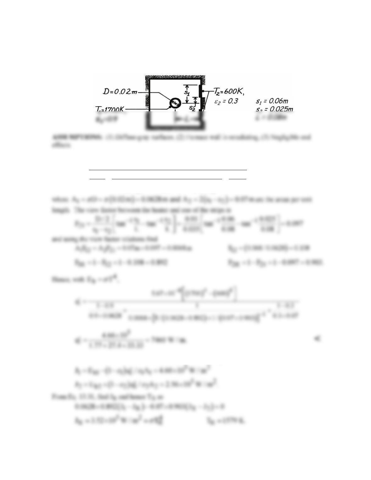
ANALYSIS: From an energy balance on surface A2,
Hence, Eq. (1) with J3 = 5.67 × 10-8 × 3004 W/m2 becomes
The radiation balance on surface A1 with Eb1 = 5.67 × 10-8 × 6004 W/m2 becomes
Solve Eqs. (2) and (4) to find J2 = 3812 W/m2 and since Eb2 = J2,
PROBLEM 13.51
KNOWN: Thermal conditions in oven used to cure strip coatings.
FIND: Electrical power requirement.
SCHEMATIC:
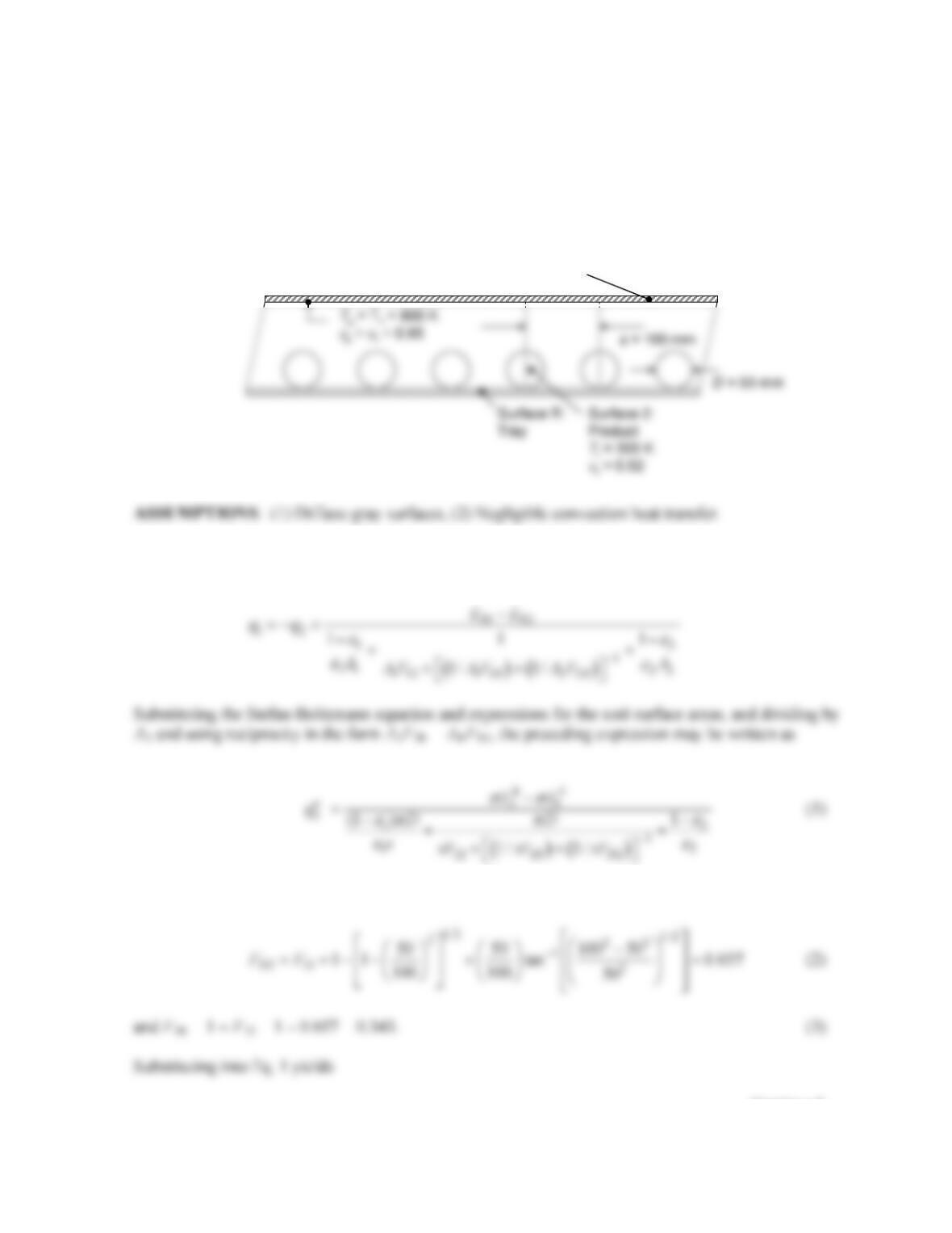
ANALYSIS: The net radiant power leaving the heater surface per unit length is
( ) ( )
b1 b2
112
1
11 2 2
112 11R 2 2R
EE
q1 11
AA
A F 1/ A F 1/A F
εε
εε
−
−
′=−−
++
++
COMMENTS: The radiosities for A1 and A2 follow from Eq. 13.19,
PROBLEM 13.52
KNOWN: Dimensions, temperature and emissivity of cylindrical product. Temperature and
emissivity of infrared panel heater.
FIND: (a) Radiative flux delivered to the product and panel heat flux for a spacing of s = 100 mm and
a product length of L = 1 m, (b) Plot of the heat flux experienced by the product, and the panel heater
heat flux over the range 50 mm ≤ s ≤ 250 mm.
SCHEMATIC:
ANALYSIS: (a) For the unit cell indicated in the schematic, A1 = A3 = AR = s and A2 =
π
D. From Eq.
13.30,
The view factors are evaluated using the expression given in Table 13.1,
Continued…
Surface 1:
Panel heater
PROBLEM 13.52 (Cont.)
The panel heat flux is found by noting that
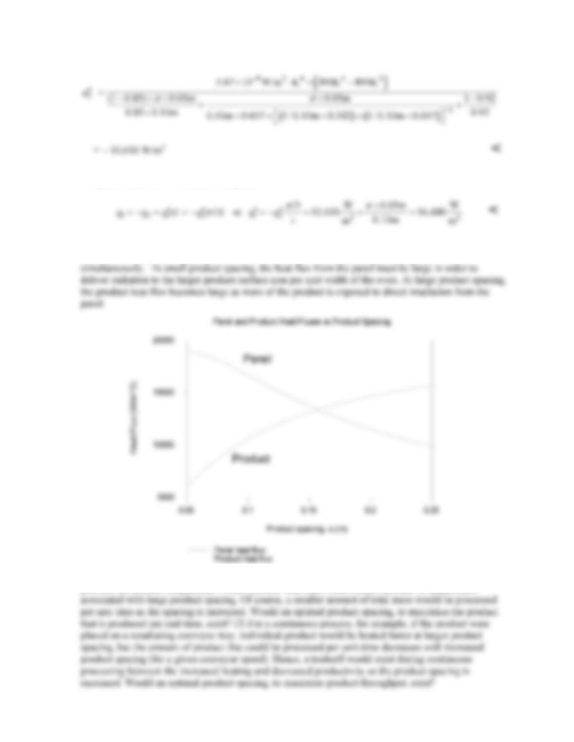
(b) Using IHT, the radiation heat flux from the panel and the radiation heat flux to the product, as a
function of the product spacing, s, is shown below. This was obtained by solving Eqs. 1 – 3
COMMENTS: (1) The product may be heated by a batch or a continuous process. (2) For a batch
process, the product temperature would increase with time, with a faster increase in temperature
PROBLEM 13.53
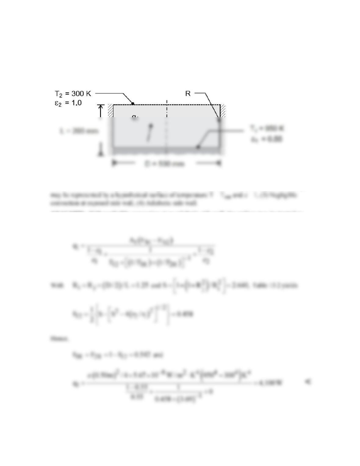
KNOWN: Surface temperature and emissivity of molten alloy and distance of surface from top of
container. Container diameter.
FIND: Net rate of radiation heat transfer from surface of melt.
SCHEMATIC:
ASSUMPTIONS: (1) Opaque, diffuse, gray behavior for surface of melt, (2) Large surroundings
ANALYSIS: With negligible convection at an adiabatic side wall, the surface may be treated as
reradiating. Hence, from Eq. 13.30, with A1 = A2,
PROBLEM 13.54
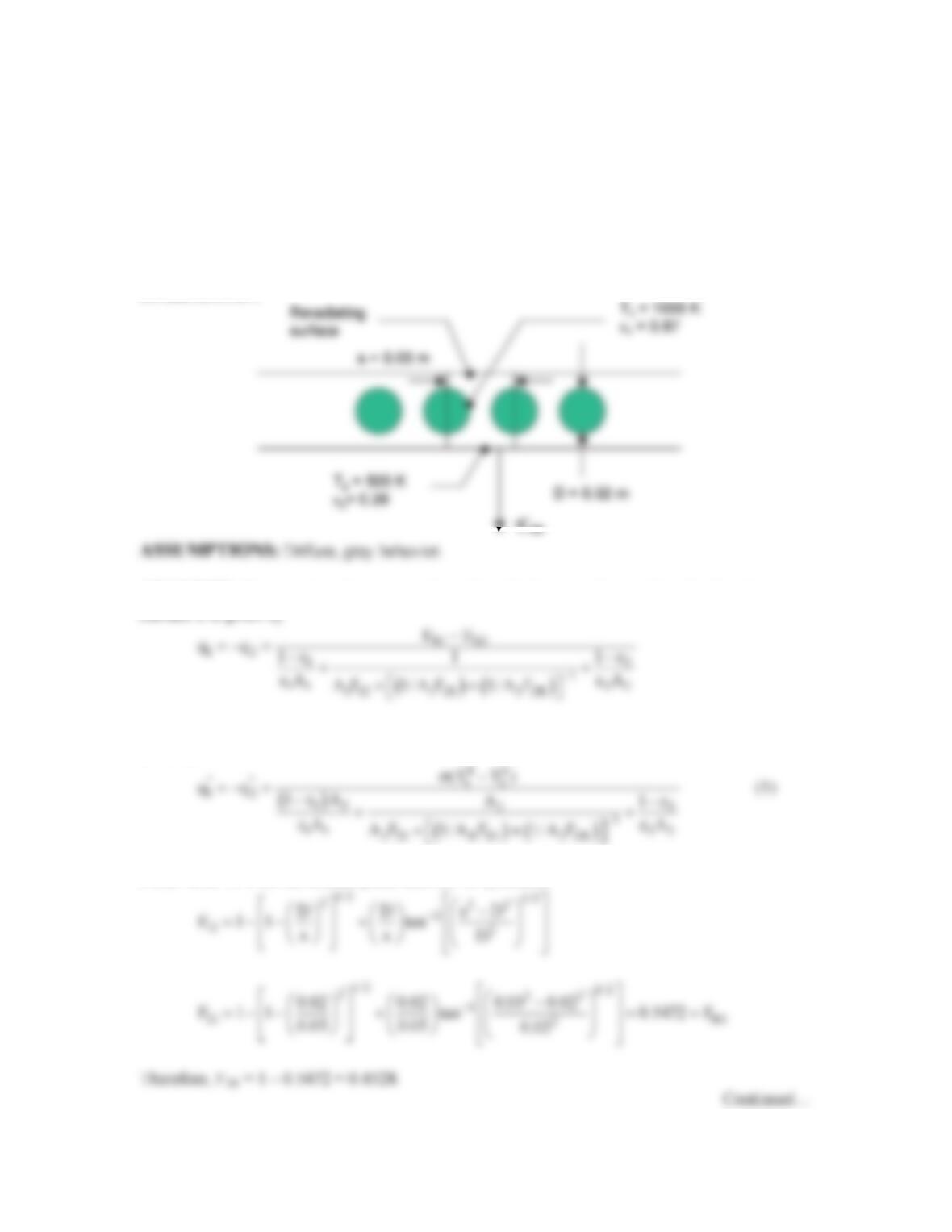
KNOWN: Dimensions, temperature and emissivity of radiant heating tubes, temperature and
emissivity of heated material, location of reradiating surface.
FIND: Net radiative heat flux to the heated material.
SCHEMATIC:
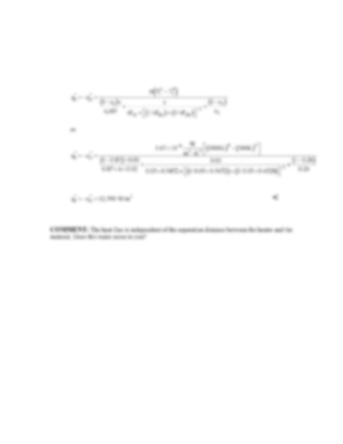
ANALYSIS: Treating the tubes as a single surface, the heat transfer rate from Surface 1 to
Utilizing the reciprocity relationship, incorporating the Stefan-Boltzmann law, and dividing by
area A2,
From Table 13.1 for the infinite plane and row of cylinders,
q”
q”
PROBLEM 13.54 (Cont.)
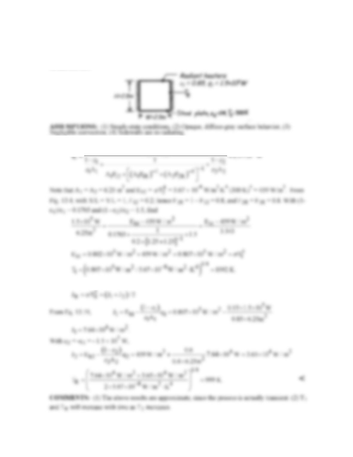
For a unit cell as shown in the schematic, A2 = s, A1 = πD, and AR = s. Therefore Eq. (1) is
written as,
PROBLEM 13.55
KNOWN: Configuration and operating conditions of a furnace. Initial temperature and emissivity of
steel plate to be treated.
FIND: (a) Heater temperature, (b) Sidewall temperature.
SCHEMATIC:
ANALYSIS: (a) From Eq. 13.30
5
b1 b2
EE
−
(b) From Eq. 13.31, it follows that, with A1F1R = A2F2R,