PROBLEM 13.30 (Cont.)
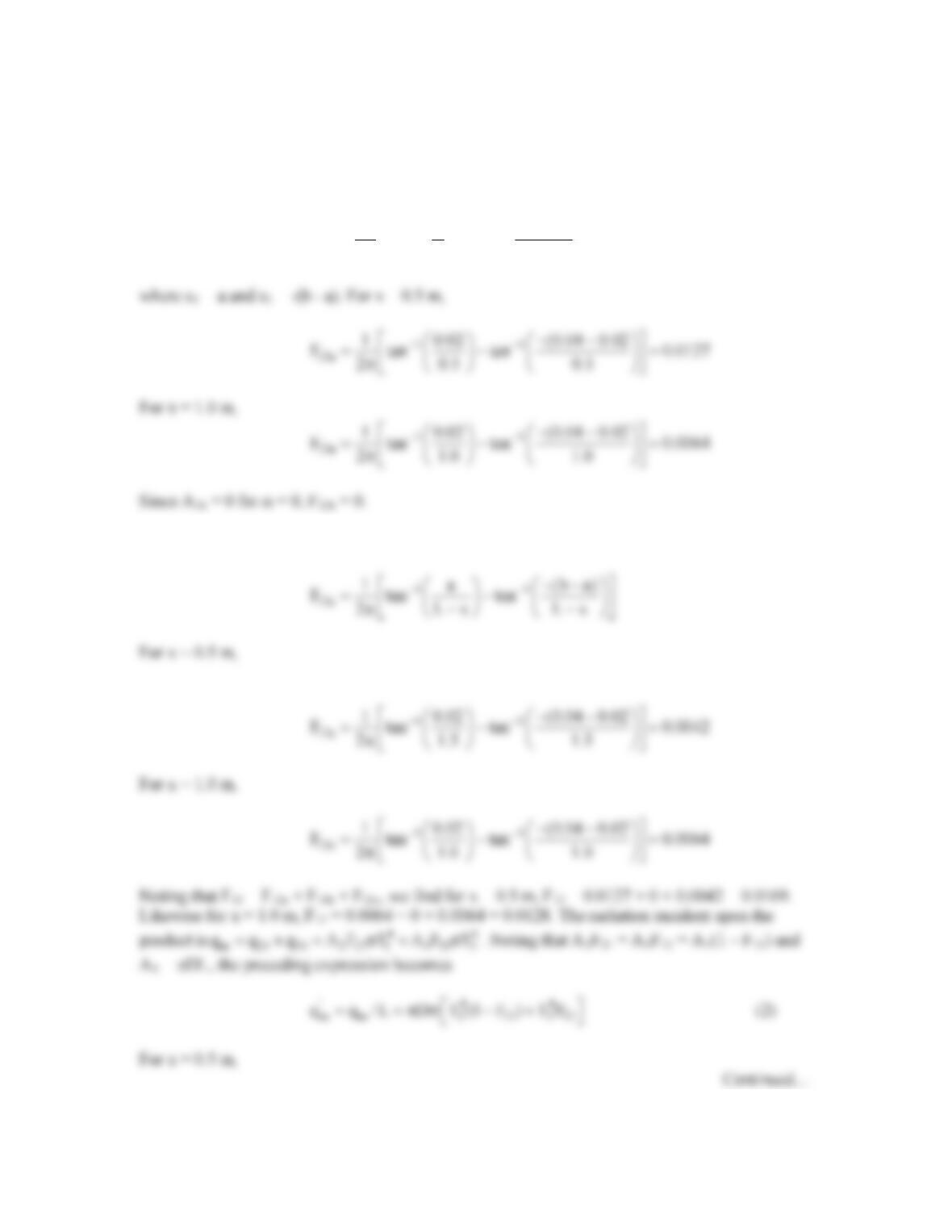
(a) For α = 0,
11
13a
1 a (b a)
F tan tan
2x x
−−
−−
= −
π
For F13c we note that s1 = a and s2 = -(b – a). Therefore,
PROBLEM 13.30 (Cont.)
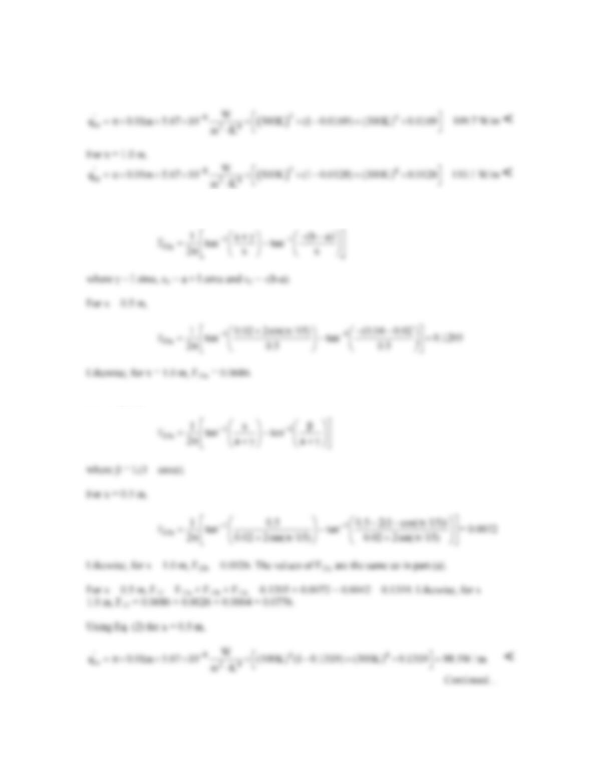
(b) For α = π/15,
From Eq. (1),
PROBLEM 13.30 (Cont.)
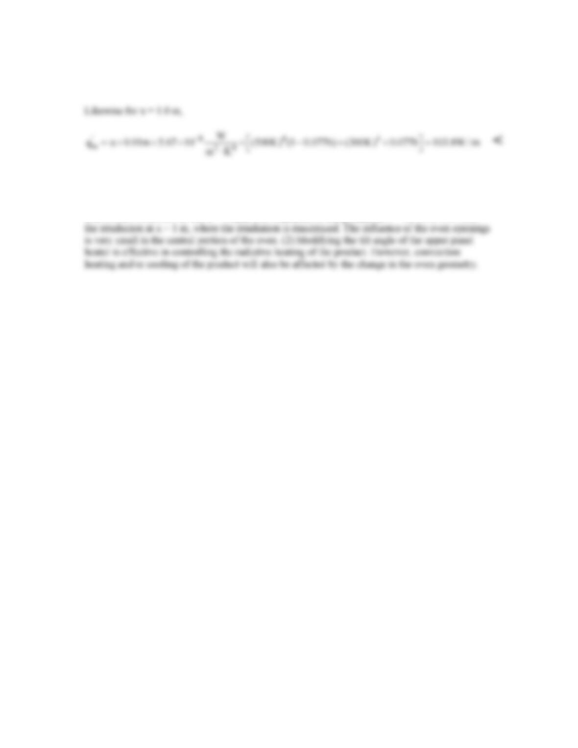
COMMENTS: (1) For the α = 0 case, the irradiation of the product at x = 0.5 m is 99.6 % of
PROBLEM 13.31
KNOWN: Two horizontal, very large parallel plates with prescribed surface conditions and
temperatures.
FIND: (a) Irradiation to the top plate, G1, (b) Radiosity of the top plate, J1, (c) Radiosity of the
lower plate, J2, (d) Net radiative exchange (W/m2) between the plates per unit area of the plates.
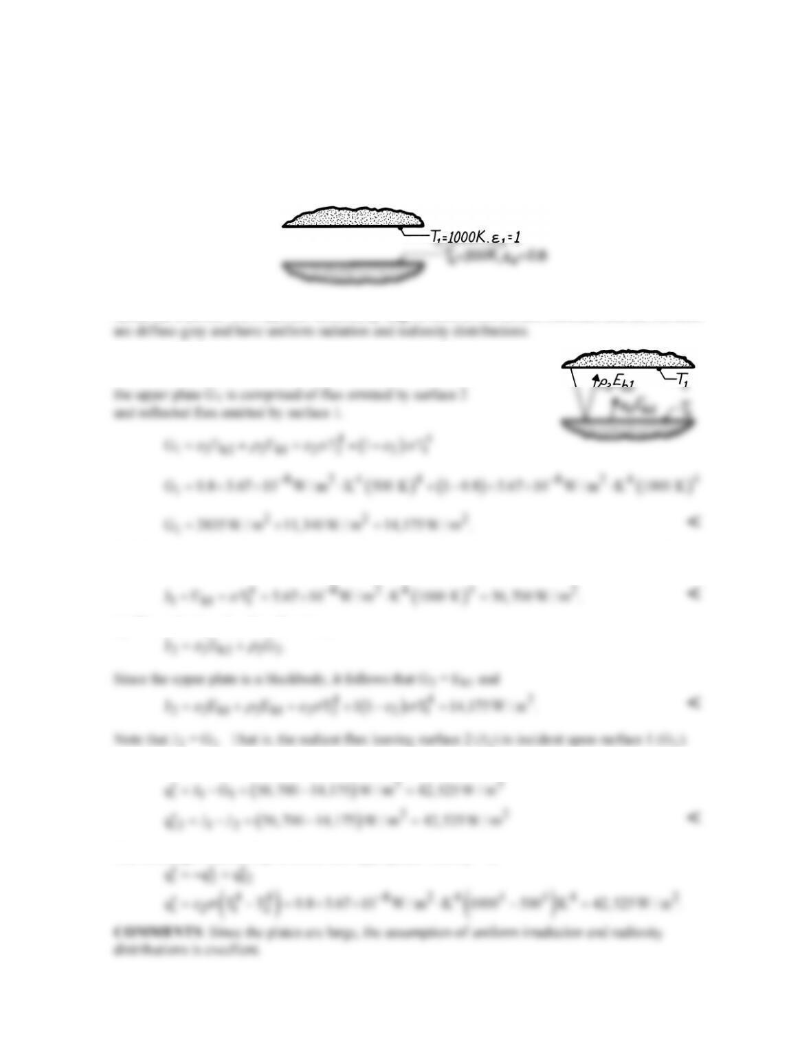
SCHEMATIC:
ASSUMPTIONS: (1) Plates are sufficiently large to form a two surface enclosure and (2) Surfaces
ANALYSIS: (a) The irradiation to the upper plate is defined
as the radiant flux incident on that surface. The irradiation to
(b) The radiosity is defined as the radiant flux leaving the surface by emission and reflection. For the
blackbody surface 1, it follows that
(c) The radiosity of surface 2 is then,
(d) The net radiation heat exchange per unit area can be found by three relations.
The exchange relation, Eq. 13.24, is also appropriate with ε1 = 1,
PROBLEM 13.32
KNOWN: Concentric spheres of large and small surface area.
FIND: (a) Ratio of sphere radii, r2/r1, for which radiation heat rates predicted by Equation 1.7 are
within 1 percent of rate provided by Equation 13.26, (b) plot of required radius ratio versus emissivity
of the larger of the two spheres, ε2.
SCHEMATIC:
ASSUMPTIONS: Surfaces are diffuse–gray.
ANALYSIS: From Equation 13.26, the exact expression for the radiation heat rate is
while from Equation 1.7 the approximate expression is
From a comparison of Equations (1) and (2) it is evident that q12a > q12,e. From the problem statement, q12a = 1.01q12e .
Substituting Equations 1 and 2 into this expression yields
PROBLEM 13.32 (Cont.)
For ε1 = ε2 = 0.9 (Case 1),
( )
2
1
1 0.9
r90 3.16
r 0.9
−
= =
<
Repeating for Cases 2 through 4,
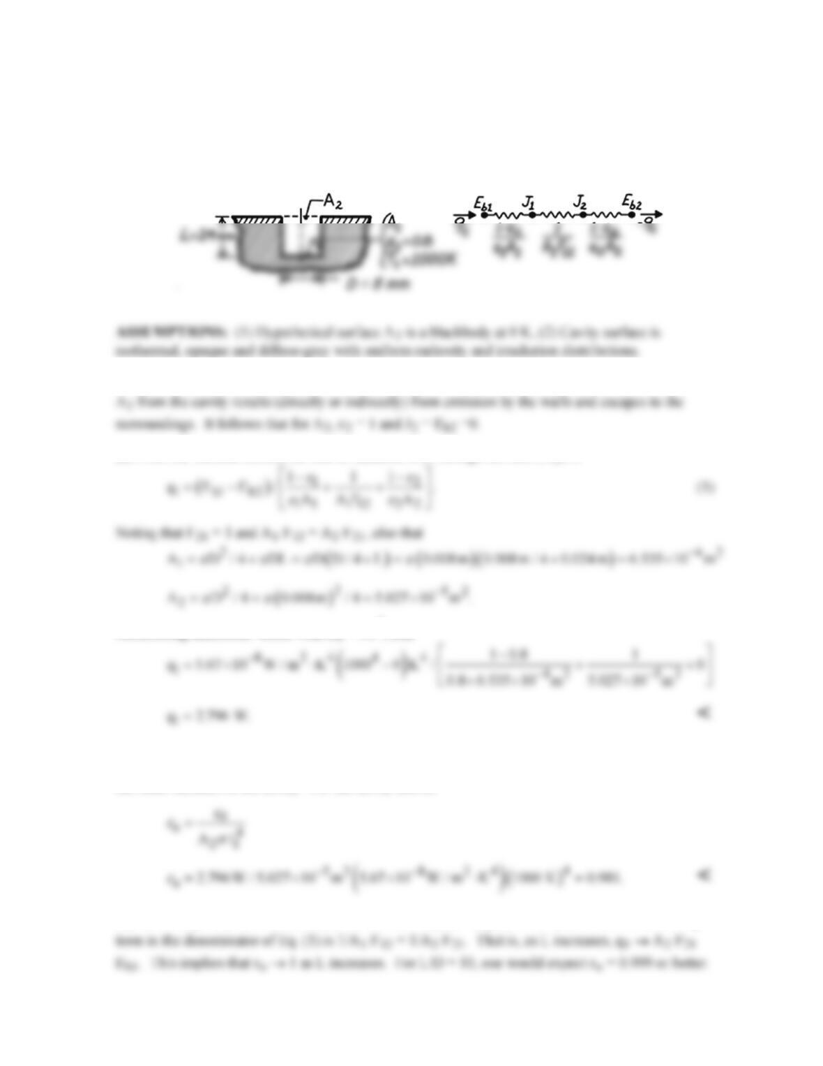
(b) The required radius ratios are shown below. As the emissivity of the outer sphere approaches that
of a blackbody, the required size of the outer sphere decreases. This effect is more pronounced at
lower emissitivies for the smaller sphere.
PROBLEM 13.33
KNOWN: Dimensions and temperature of a flat–bottomed hole.
FIND: (a) Radiant power leaving the opening, (b) Effective emissivity of the cavity, εe, (c) Limit of
εe as depth of hole increases.
SCHEMATIC:
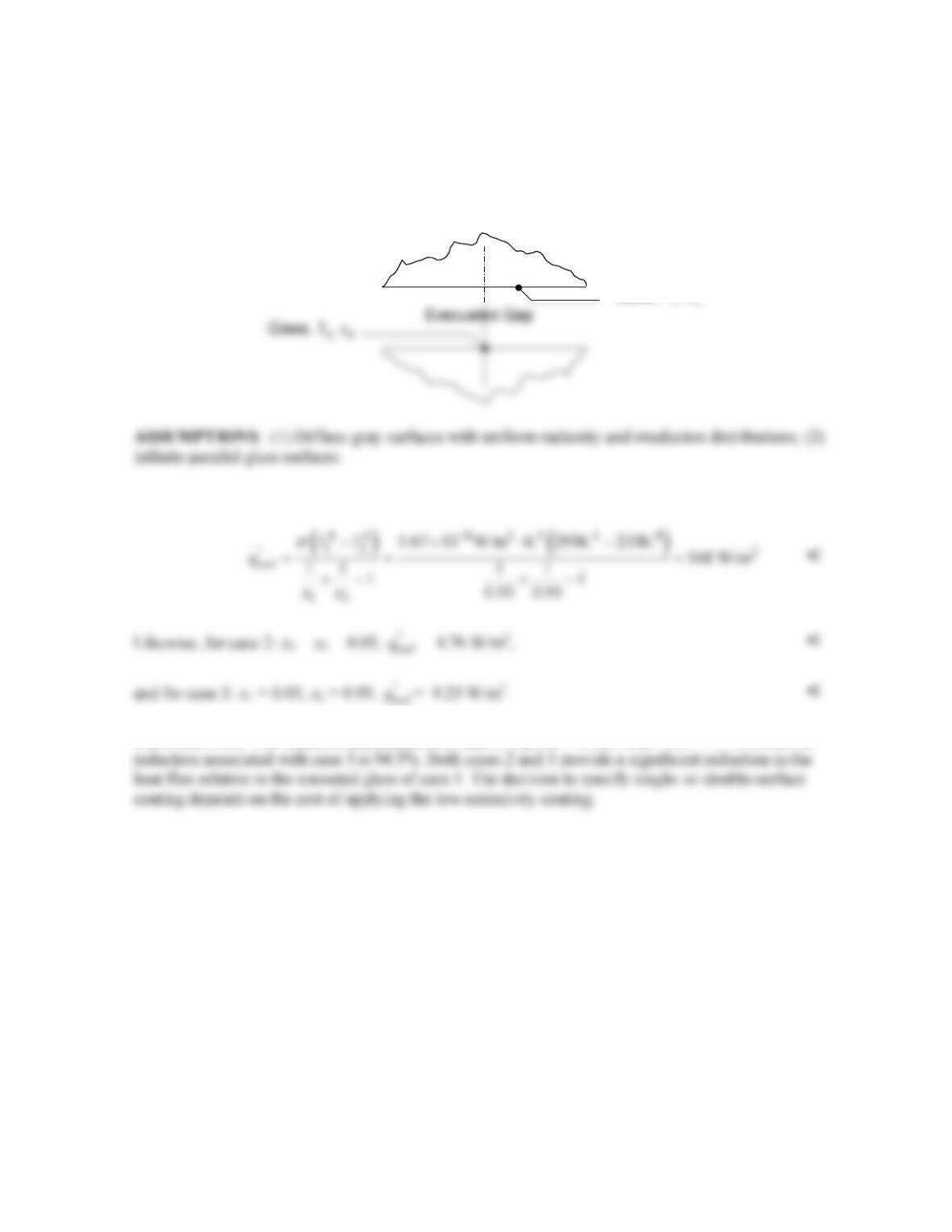
ANALYSIS: Approximating A2 as a blackbody at 0 K implies that all of the radiation incident on
(a) From the thermal circuit, the rate of radiation loss through the hole (A2) is
Substituting numerical values with Eb = σT4, find
(b) The effective emissivity, εe, of the cavity is defined as the ratio of the radiant power leaving the
cavity to that from a blackbody having the same area of the cavity opening and at the temperature of
the inner surfaces of the cavity. For the cavity above,
(c) As the depth of the hole increases, the term (1 – ε1)/ε1 A1 goes to zero such that the remaining
PROBLEM 13.34
KNOWN: Temperatures and emissivity of glass surfaces.
FIND: Heat flux through the window for case 1:
ε
1 =
ε
2 = 0.95, case 2:
ε
1 =
ε
2 = 0.05, and case 3:
ε
1
= 0.05,
ε
2 = 0.95.
SCHEMATIC:
ANALYSIS: For case 1, the net radiation heat flux between the glass sheets is
COMMENTS: The reduction associated with case 2 is [(168 – 4.76)/168] × 100 = 97 % while the
Glass, T
,ε
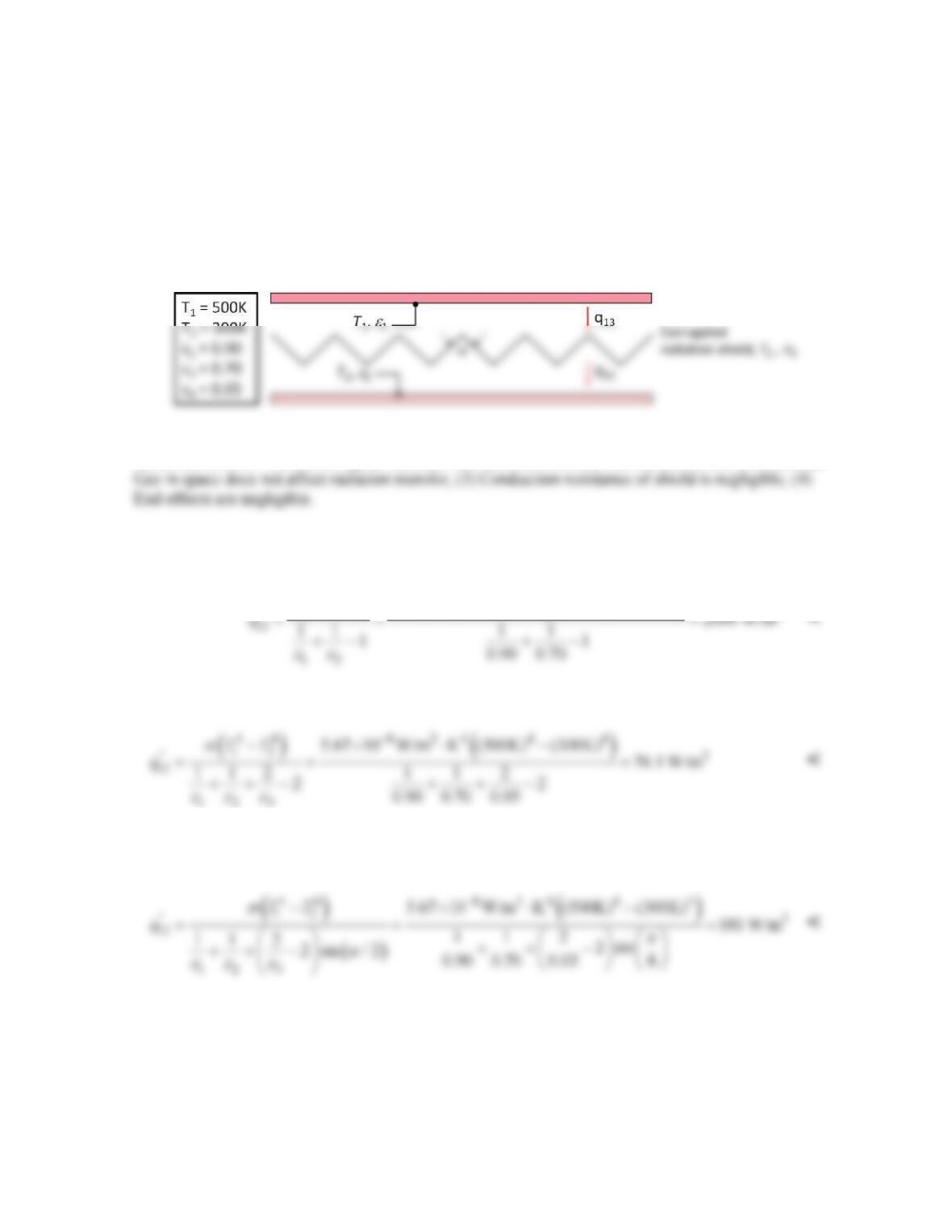
PROBLEM 13.35
KNOWN: Temperatures and emissivity of large parallel plates. Emissivity of radiation shield. Crease
angle
α
.
FIND: (a) Heat flux without a shield and with a flat shield (
α
=
π
), (b) Heat flux with
α
=
π
/4, (c)
Plot of heat flux with no shield, with flat shield, and with corrugated shield over 1 <
α
<
π
.
SCHEMATIC:
ASSUMPTIONS: (1) Diffuse–gray surfaces with uniform radiosity and irradiation distributions, (2)
ANALYSIS: (a) Without the shield Equation 13.24 yields
( ) ( )
4 4 8 24 4 4
12
“2
5.67 10 W/m K (500K) (300K)
TT
σ
−
−×⋅ −
With the flat shield in place (
α
= π), Equation 13.28 reduces to
(b) With the corrugated sheet, and recognizing that F13 = F23 = 1 and A1/A3 = A2/A3 = sin(
α
/2),
Equation 13.28 reduces to
Adding foil by modifying the crease angle is more effective than using no shield, but is less effective
than adding a flat foil. <
Continued…
PROBLEM 13.35 (Cont.)
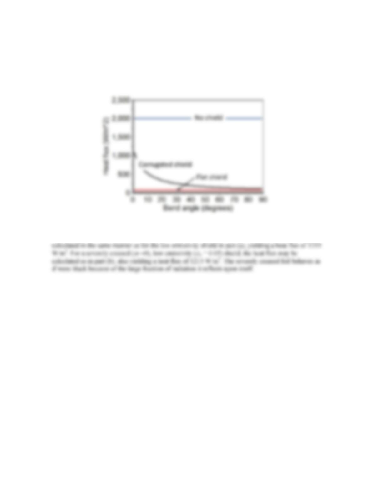
(c) The radiation flux between the plates with no shield, with a flat shield, and with a corrugated shield
at various crease angles is shown below. As the angle
α
decreases, radiation that strikes the foil from
either the top or bottom plate is partially reflected back onto the foil, resulting in more of the
irradiation being absorbed by the foil and reducing the overall radiation resistance from plate-to–plate.
COMMENTS: For a flat (
α
= π) black (
ε
3 = 1) shield, the heat flux between the plates may be
PROBLEM 13.36
KNOWN: Approximate wave geometry, hemispherical emissivity of water, ε = 0.96.
FIND: (a) Effective emissivity of the water surface for α = 3π/4, (b) Plot of the effective
emissivity normalized by the hemispherical emissivity of water, εeff/ε, over the range π/2 ≤ α ≤
π/.
SCHEMATIC:
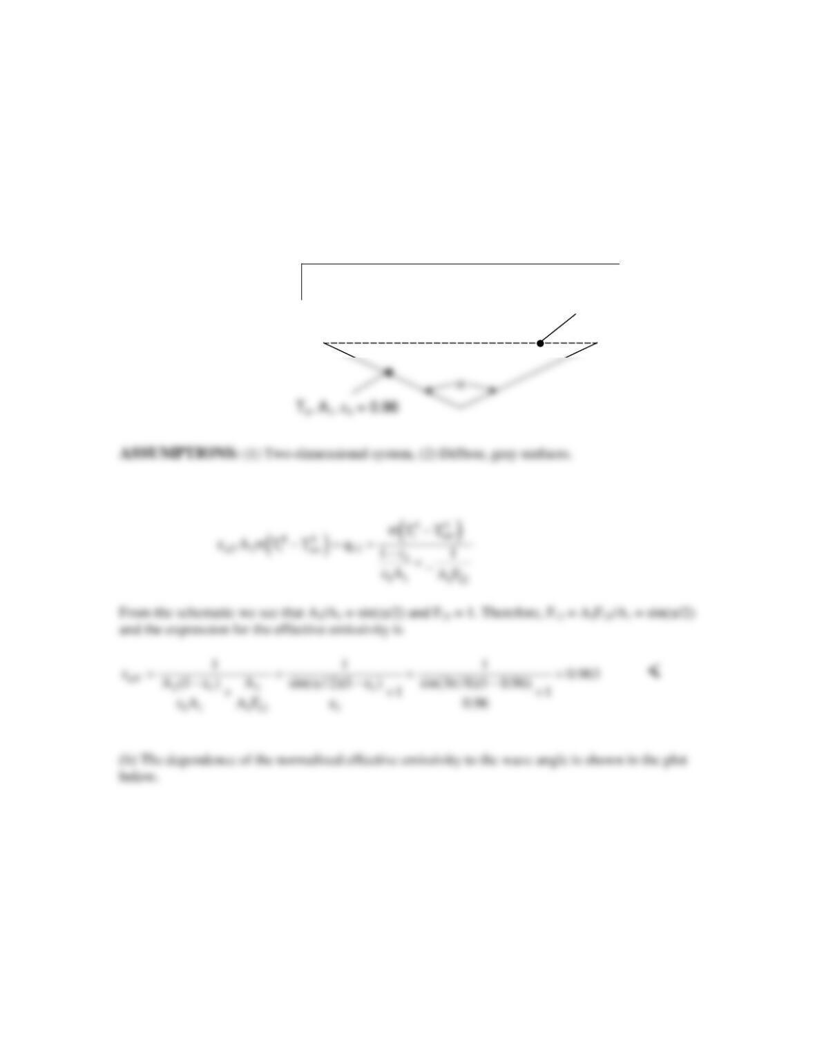
ANALYSIS: (a) The effective emissivity is defined by the relation
Continued…
A2
Tsur
A2
Tsur
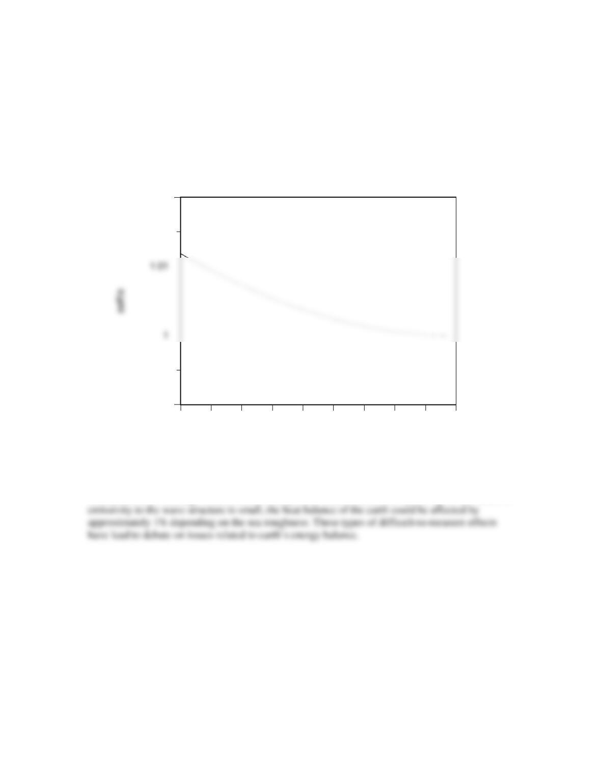
PROBLEM 13.36 (Cont.)
Normalized Effective Emissivity vs. Wave Structure
90 100 110 120 130 140 150 160 170 180
Wave Angle (degrees)
0.99
1.02
COMMENTS: Although water exhibits nearly black behavior, and the sensitivity of the effective
PROBLEM 13.37
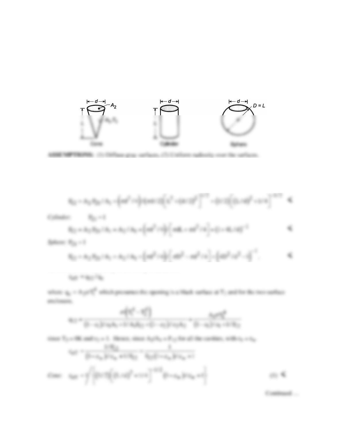
KNOWN: Cavities formed by a cone, cylinder, and sphere having the same opening size (d) and
major dimension (L) with prescribed wall emissivity.
FIND: (a) View factor between the inner surface of each cavity and the opening of the cavity; (b)
Effective emissivity of each cavity as defined in Problem 13.33, if the walls are diffuse–gray with εw;
and (c) Compute and plot εe as a function of the major dimension-to–opening size ratio, L/d, over the
range from 1 to 10 for wall emissivities of εw = 0.5, 0.7, and 0.9.
SCHEMATIC:
ANALYSIS: (a) Using the summation rule and reciprocity, determine the view factor F12 for each of
the cavities considered as a two–surface enclosure.
Cone:
21 22 21 21
F F F 01 F 1+ = += =
(b) The effective emissivity of the cavity is defined as
PROBLEM 13.37 (Cont.)
Cylinder:
[ ]
( )
{ }
eff
1
1ww
1 4L / d 1 / 1
ε
εε
−
=+ −+
(2) <
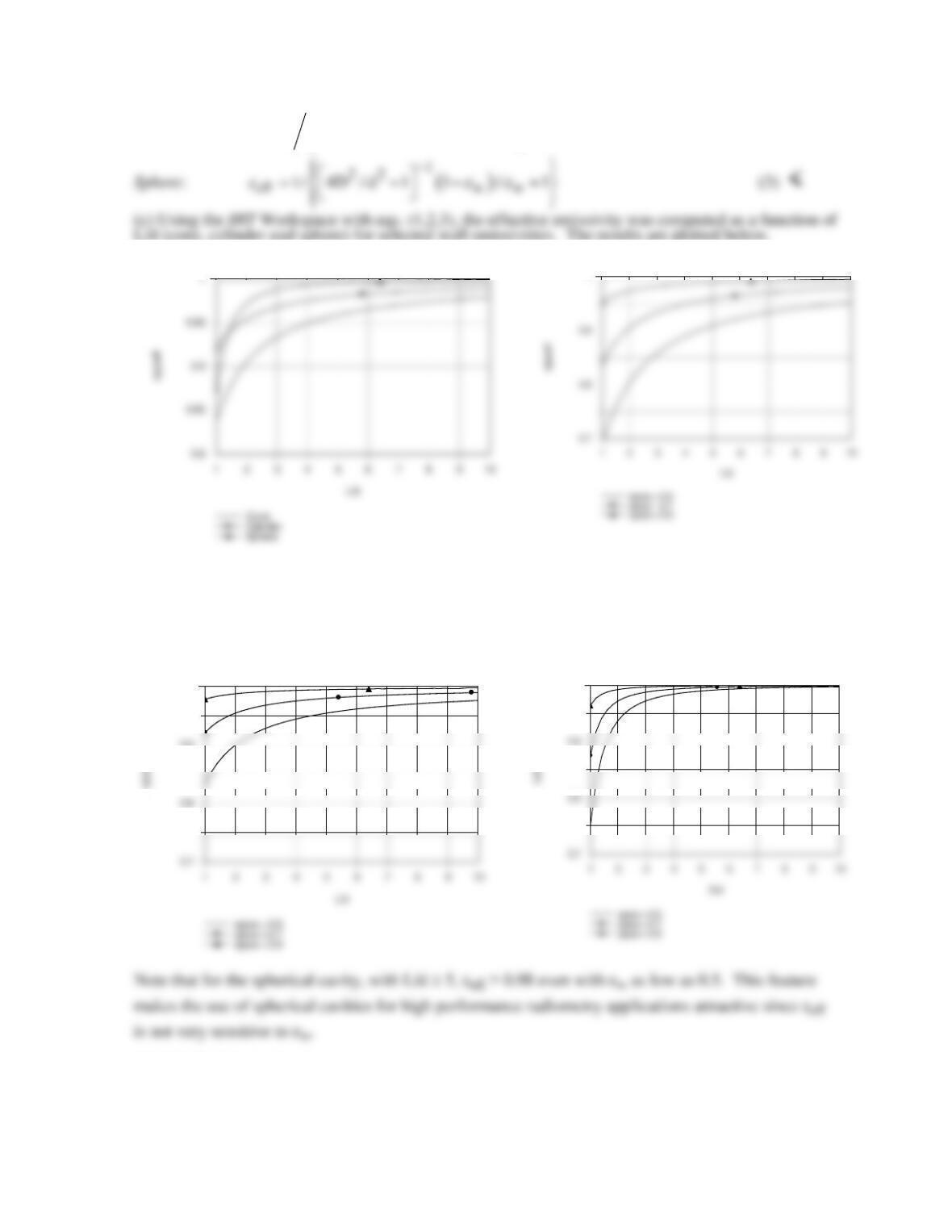
L/d (cone, cylinder and sphere) for selected wall emissivities. The results are plotted below.
1
In Fig. 1, εeff is shown as a function of L/d for εw = 0.7. For larger L/d, the sphere has the highest εeff
and the cone the lowest. Figures 2, 3 and 4 illustrate the εeff vs. L/d for each of the cavity types. As
expected, εeff increases with increasing wall emissivity.
COMMENTS: In Fig. 1, comparing εeff for the three cavity types, can you give a physical
explanation for the results?
Fig. 1 Cone, cylinder, sphere cavities, eps = 0.7
Fig 2 Conical cavity
Fig 3 Cylindrical cavity
0.9
1
Fig 4 Spherical cavity
1
PROBLEM 13.38
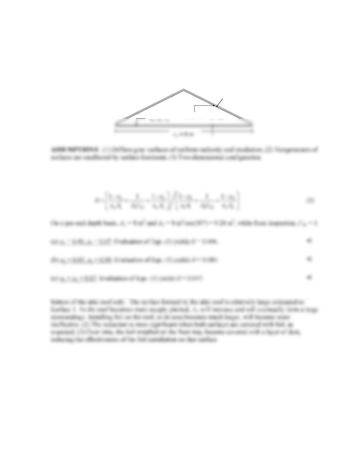
KNOWN: Dimensions of attic. Emissivity of aluminum foil and of surfaces prior to application of
the foil .
FIND: (a) Reduction of radiation heat transfer from the hot roof to the attic floor if foil is installed on
the bottom of the roof, (b) Reduction in radiation heat load if foil is installed on the top of the attic
floor, (c) Reduction if foiled is installed on both the attic floor and bottom of roof.
SCHEMATIC:
ANALYSIS: From Eqn. 13.23 we know that the ratio of the radiation heat load after installation of
the foil to the radiation heat load prior to the installation of the foil is
COMMENTS: (1) The reduction in the radiation heat load is least when the foil is installed on the
Attic
A2,
ε
2, T2
θ
= 30°
PROBLEM 13.39
KNOWN: Dimensions and temperature of an anodized aluminum sheet radiating to deep space.
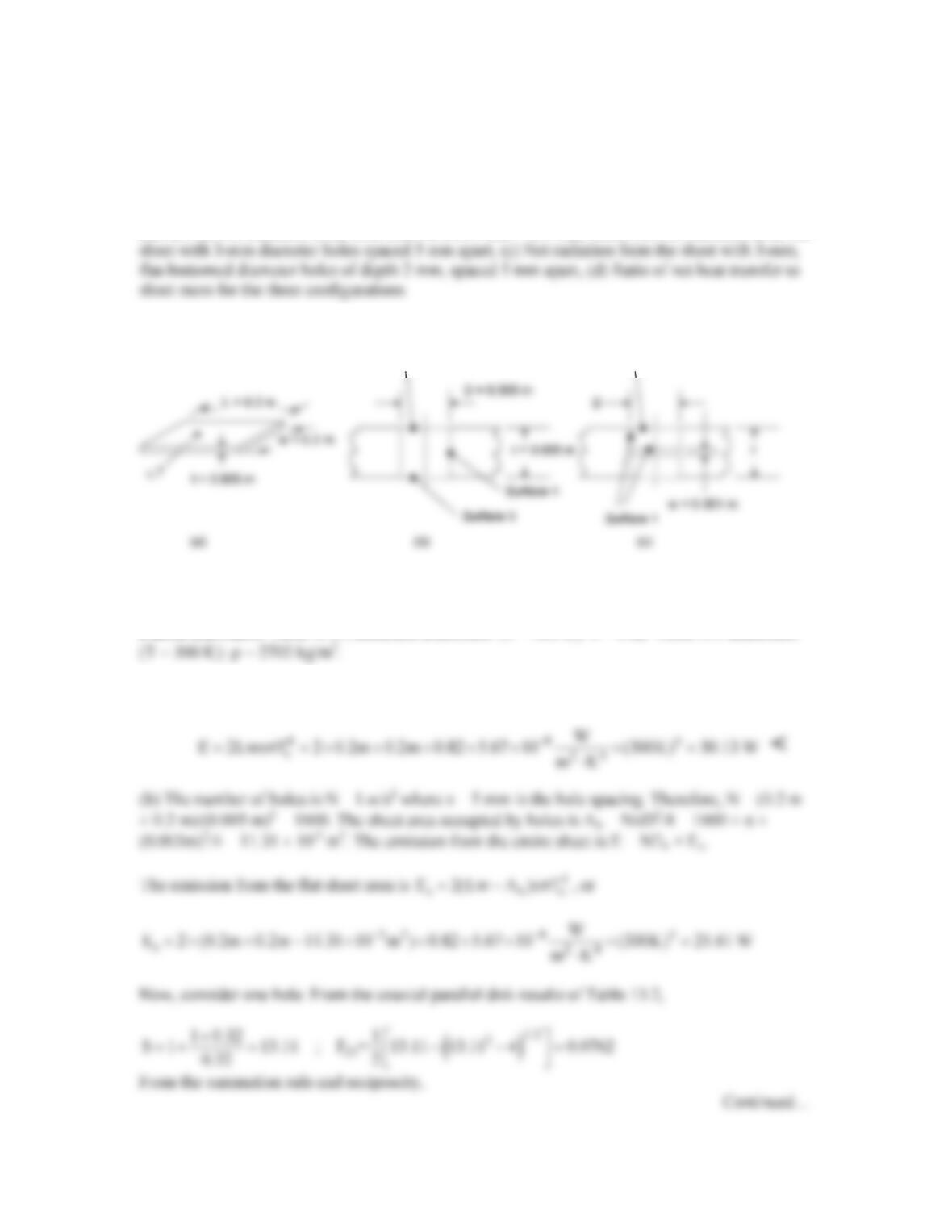
FIND: (a) Net radiation from both sides of a 200 mm × 200 mm sheet, (b) Net radiation from the
SCHEMATIC:
ASSUMPTIONS: Diffuse, gray behavior.
PROPERTIES: Table A.11, anodized aluminum: (T = 300 K): ε = 0.82. Table A.1 aluminum
ANALYSIS: (a) For 2 sides,
Surface 2
Surface 2
Surface 2
Surface 2
Surface 2
PROBLEM 13.39 (Cont.)
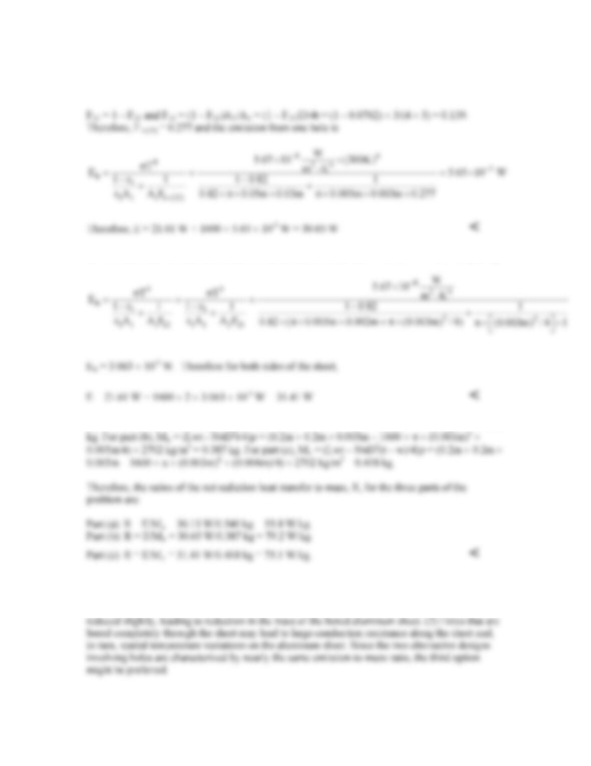
(c) We shall treat the sides and bottom of the cavity as one surface with F21 = 1. For one opening,
(d) The mass of the sheet in part (a) is Ma = Lwtρ = 0.2m × 0.2m × 0.005m × 2702 kg/m3 = 0.540
COMMENTS: (1) Boring holes in the sheet results in increased heat transfer rates and reduced
mass. If a specific heat loss is required, the size of the sheets with the bored holes could be
PROBLEM 13.40
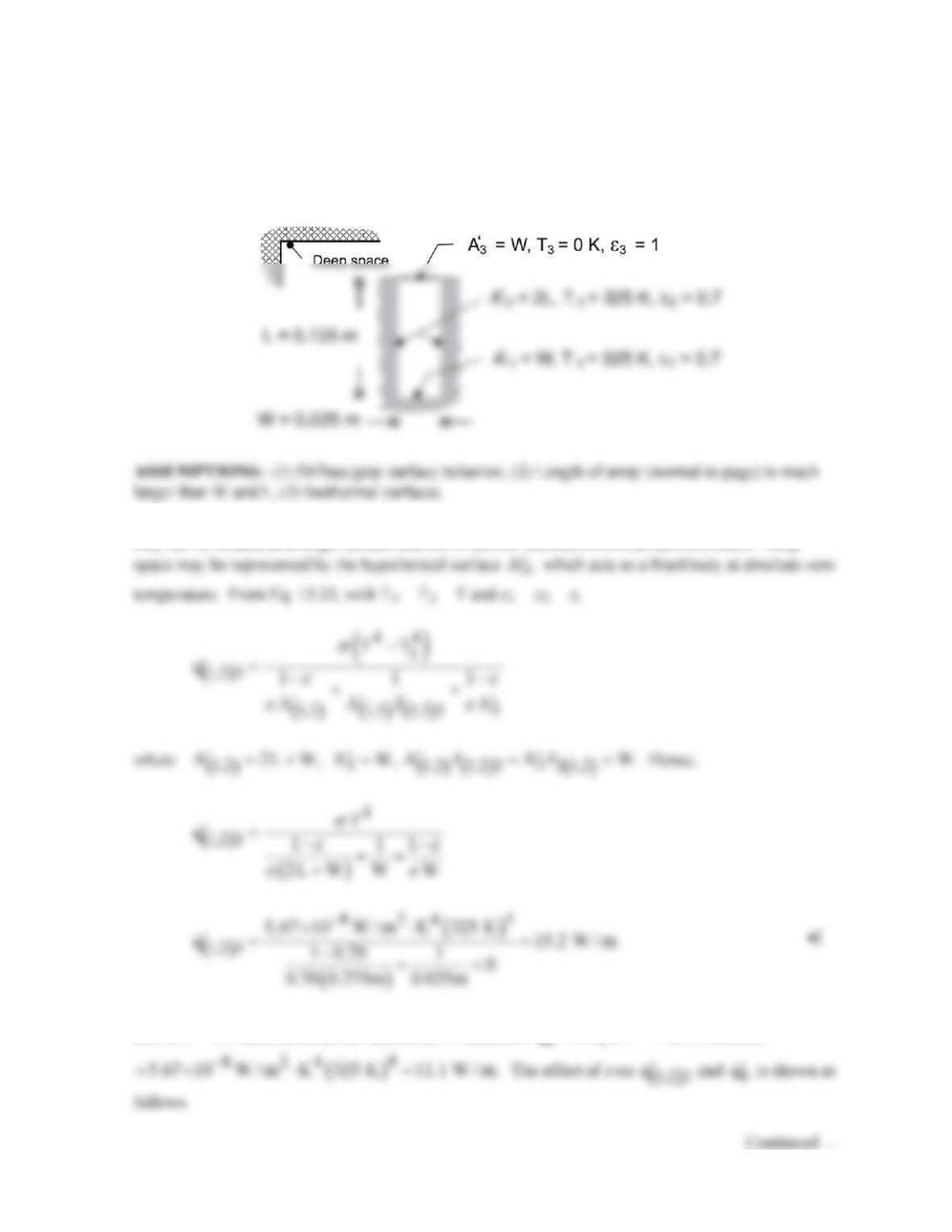
KNOWN: Temperature, emissivity and dimensions of a rectangular fin array radiating to deep space.
FIND: (a) Rate of radiation transfer per unit length from a unit section to space, (b) Effect of
emissivity on heat rejection.
SCHEMATIC:
ANALYSIS: (a) Since the sides and base of the U–section have the same temperature and emissivity,
they can be treated as a single surface and the U–section becomes a two–surface enclosure. Deep
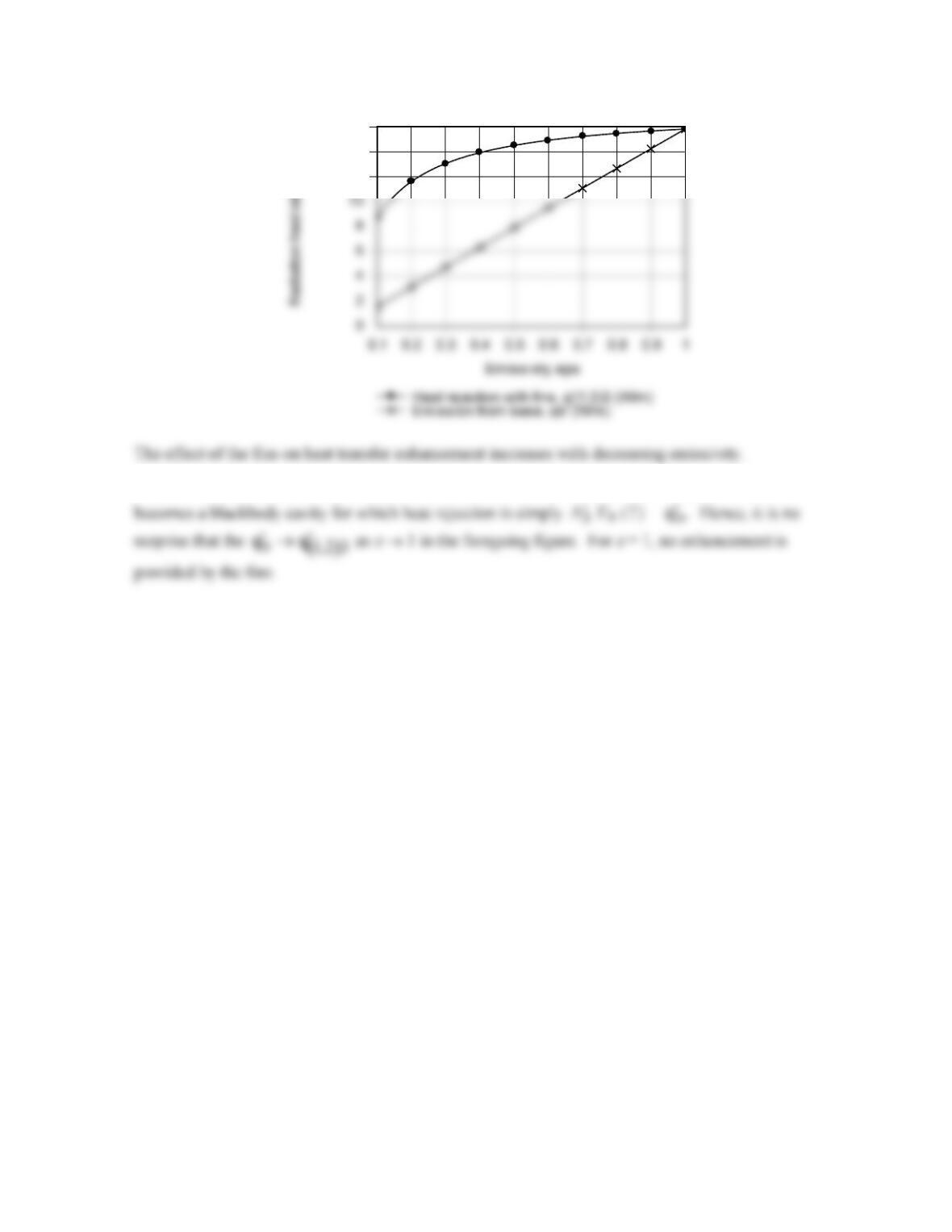
(b) For ε = 0.7 emission from the base of the U-section is
4
q AT
εσ
′′
=
0.7 0.025m= ×
PROBLEM 13.40 (Cont.)
COMMENTS: Note that, if the surfaces behaved as blackbodies (
ε
1 =
ε
2 = 1.0), the U-section
12
14
16
PROBLEM 13.41
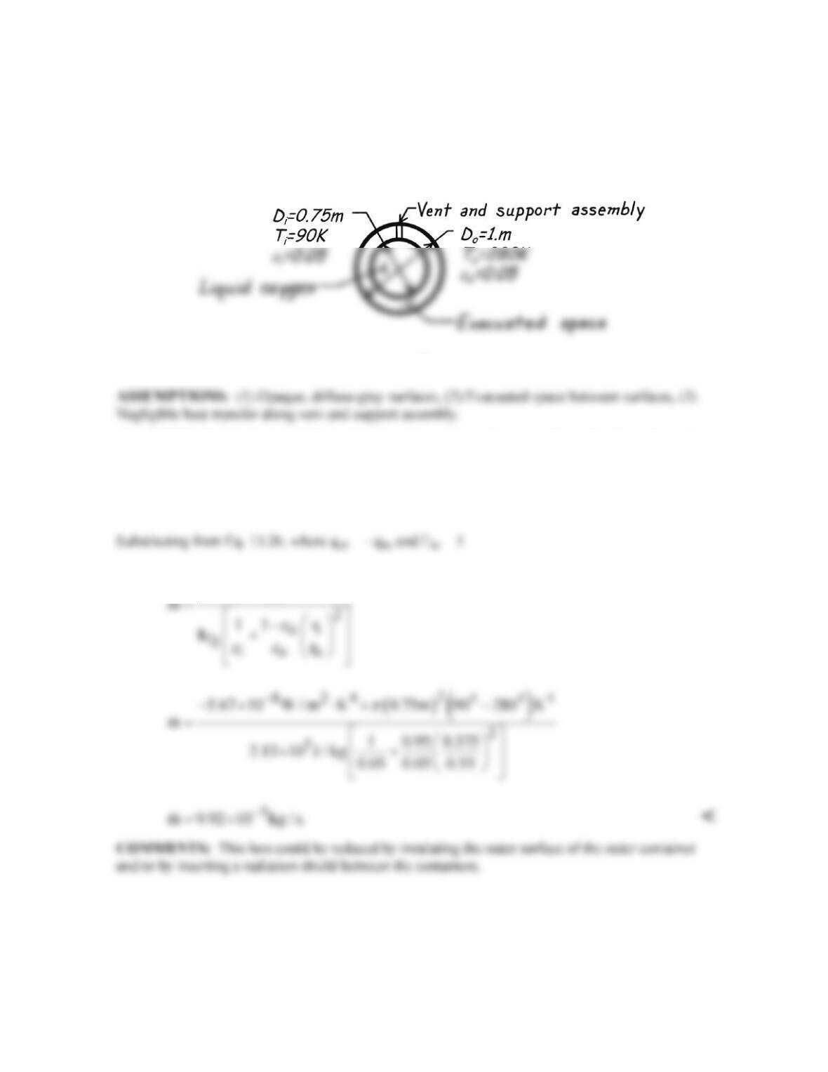
KNOWN: Temperatures and emissivities of spherical surfaces which form an enclosure.
FIND: Evaporation rate of oxygen stored in inner container.
SCHEMATIC:
PROPERTIES: Oxygen (given): hfg = 2.13 × 10⁵ J/kg.
ANALYSIS: From an energy balance on the inner container, the net radiation heat transfer to the
container may be equated to the evaporative heat loss
oi fg
q mh .=
()()
244
o
ii
DTT
σπ
−−