44
Problem 13.19
Solution:
21
21
ι
Substituting for m, , and
n in Eq. (13.1.5) gives the
modal quantities for the three modes:
536.3
11
mL
T
mι
2
333
mM
T
m
m
405.1
m
m
547.0
130.2
222
ms
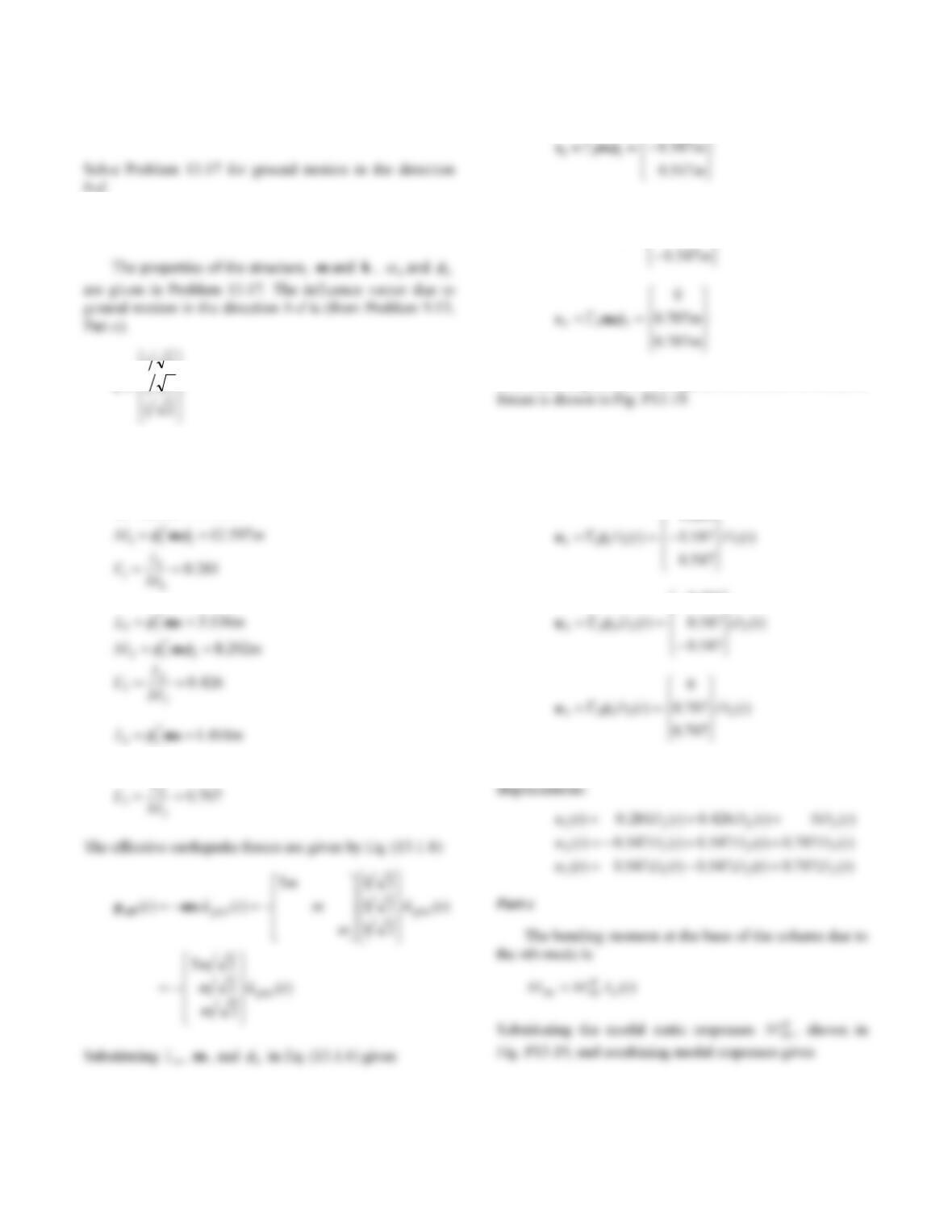
The modal expansion of the spatial distribution of effective
Part b
The modal displacements, form Eq. (13.1.10) are
281.0
426.0
Combining the modal displacements gives the total
45
The bending moment at location aof the beam due to the
nth mode is
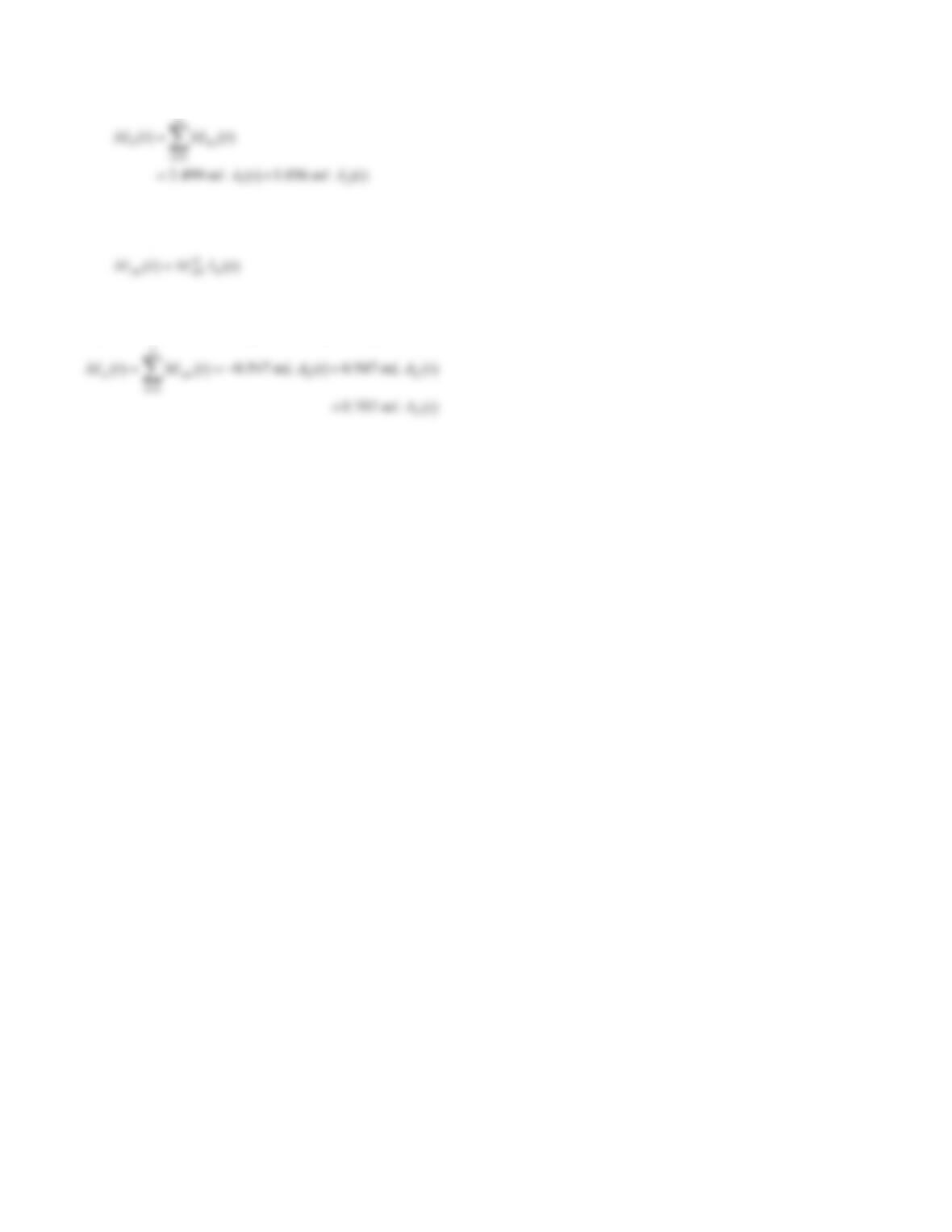
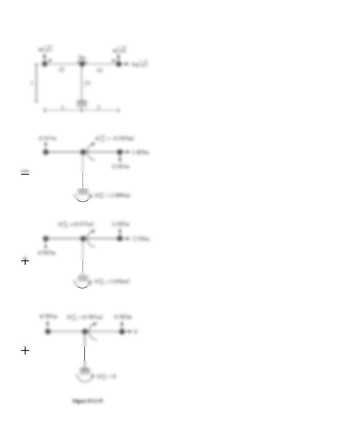
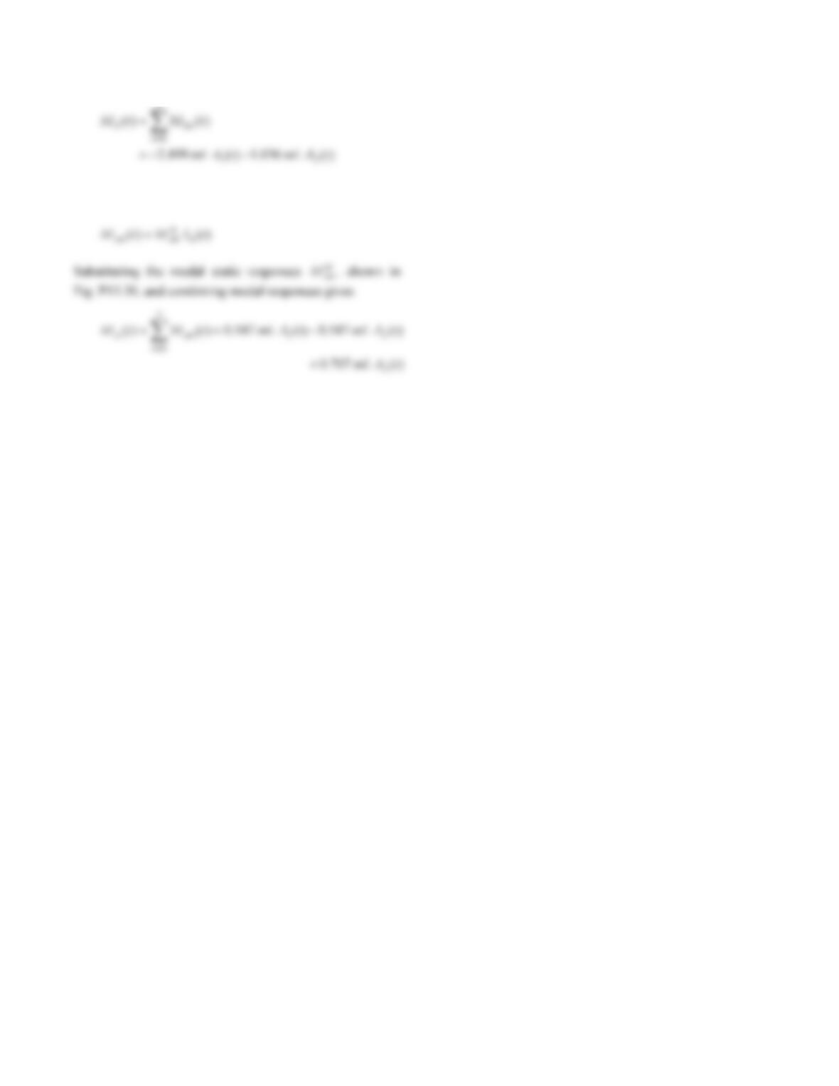
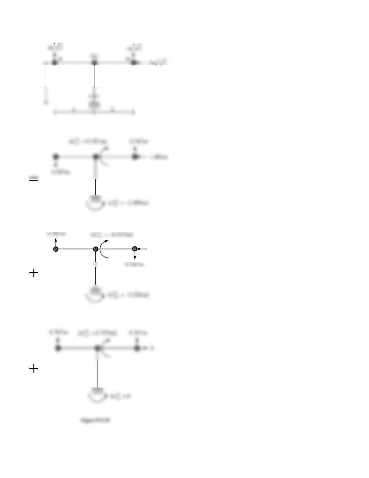
Substituting the modal static responses st
an
M, shown in
Fig. P13.19, and combining modal responses gives
46
Problem 13.20
b–c.
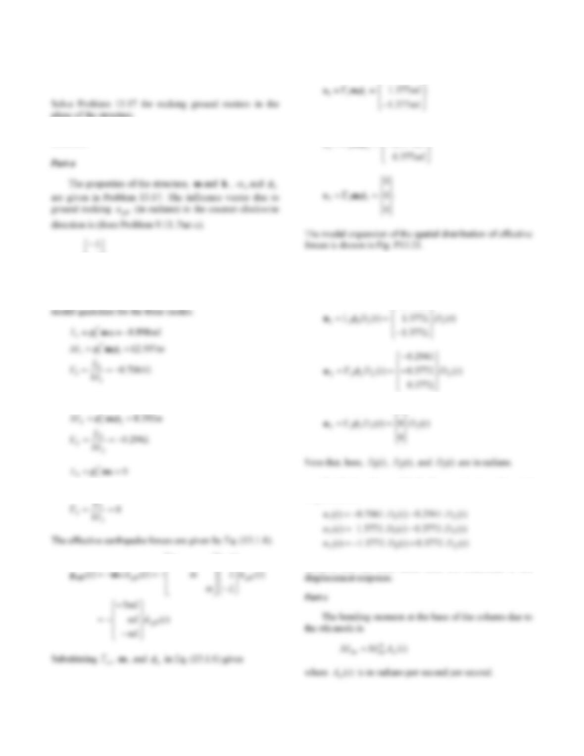
The properties of the structure, mand
k
, n
and n
21
Substituting for m, , and n
in Eq. (13.1.5) gives the
modal quantities for the three modes:
536.3
22
mL
T
T
mι
414.1
33
mL
T
mι
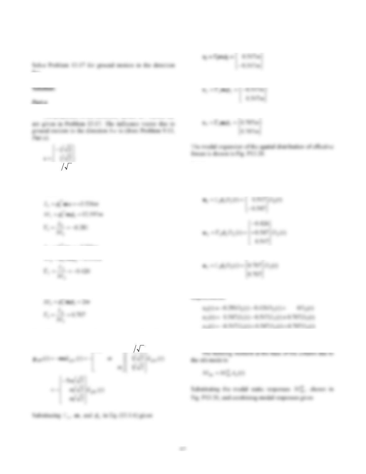
The effective earthquake forces are given by Eq. (13.1.4):
215
m
m
405.1
m
130.2
0
Part b
The modal displacements, form Eq. (13.1.10). are
281.0
0
Combining the modal displacements gives the total
3213
Part c
48
The bending moment at location aof the beam due to the
nth mode is
49
m130.2
EI
E
I
EI
L
40
Problem 13.21
plane of the structure.
Solution:
L
L
ι
Substituting for m, ι, and n
in Eq. (13.1.5) gives the
mLL
T
4348.2
22
mι
2
333
mM
T
m
5
L
m
mL
532.3
mL
mL
377.0
470.1
ms
Part b
The modal displacements, from Eq. (13.1.10), are
706.0
L
0
Combining the modal displacements gives the total
displacements:
Observe that the third mode does not contribute to the
41
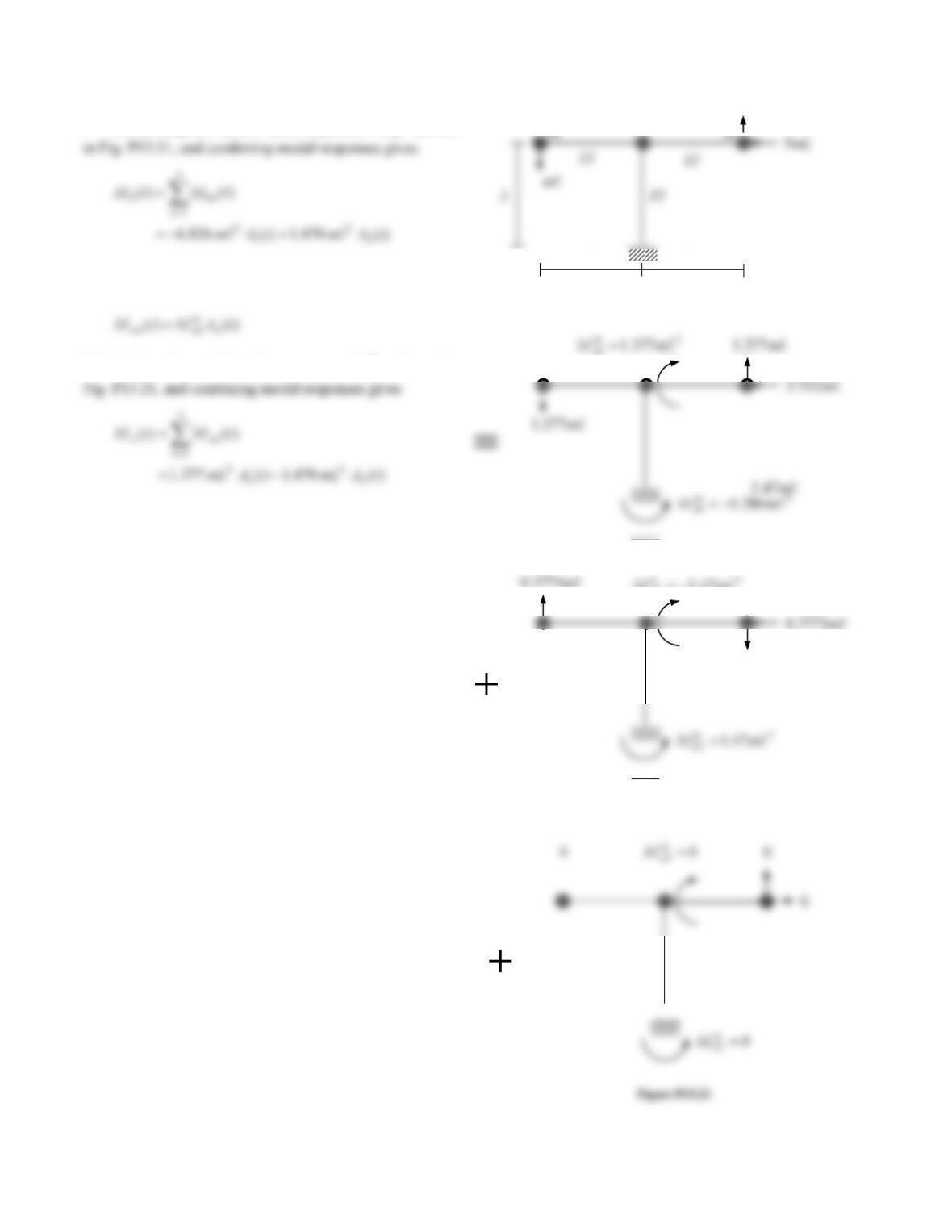
Substituting the modal static responses st
bn
M, shown
The bending moment at location
a
of the beam due to the
nth mode is
Substituting the modal static responses st
an
M, shown in
mL47.1
247.1 mLM a
mL
L L
40
Problem 13.22
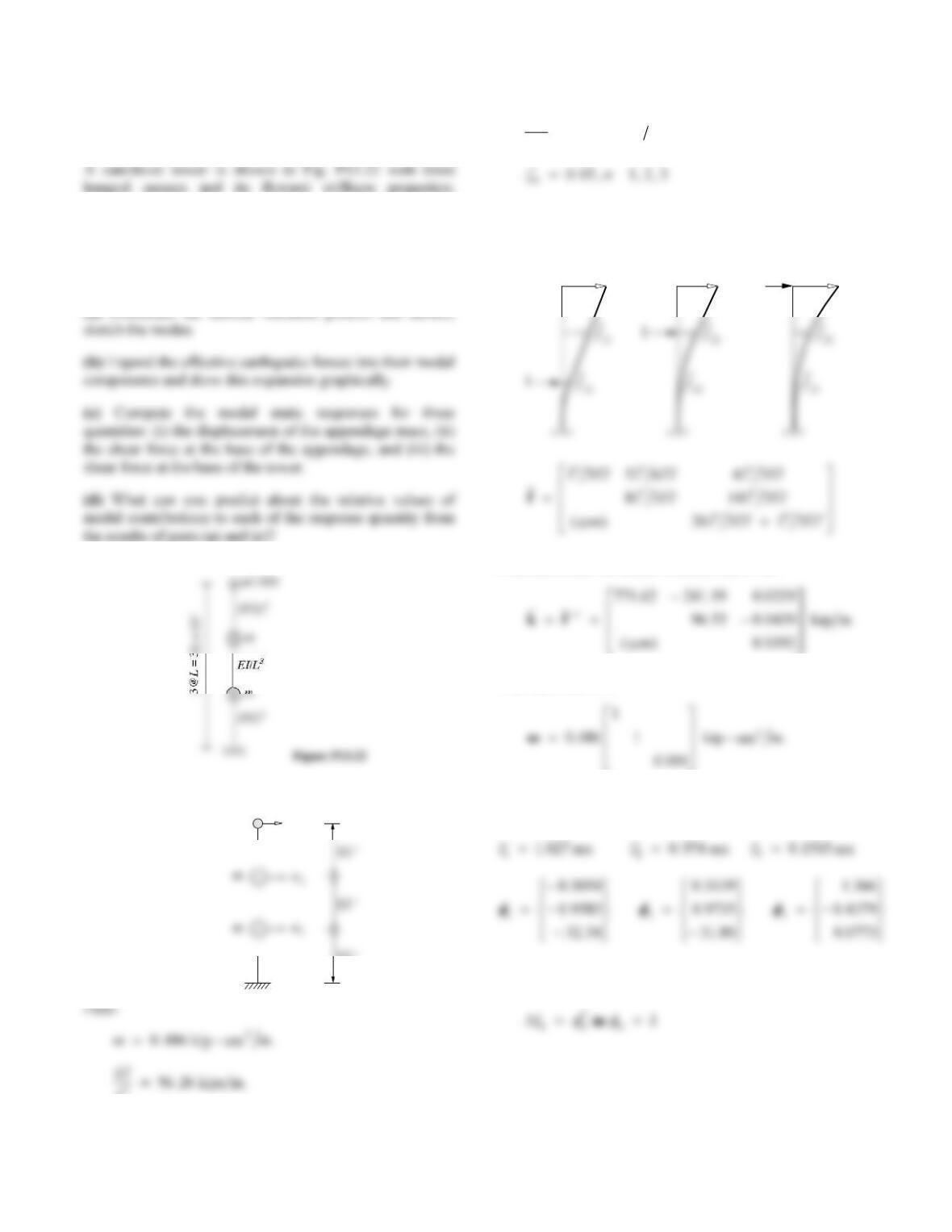
m = 0.486 kip-sec2/in., EI/L3 = 56.26 kips/in., and EIˊ/L3 =
0.0064 kip/in. Note that the top mass and its supporting
element are an appendage to the main tower. Damping is
defined by modal damping ratios, with ζn = 5% for all
modes.
(a) Determine the natural vibration periods and modes;
Solution:
u3
m/1000
10 ‘
L356 26..kips in
EI
L
30 0064..kip in
Part a
First compute the flexibility matrix:
1
f31
f32
f33
Next determine the lateral stiffness matrix
k
:
The mass matrix is
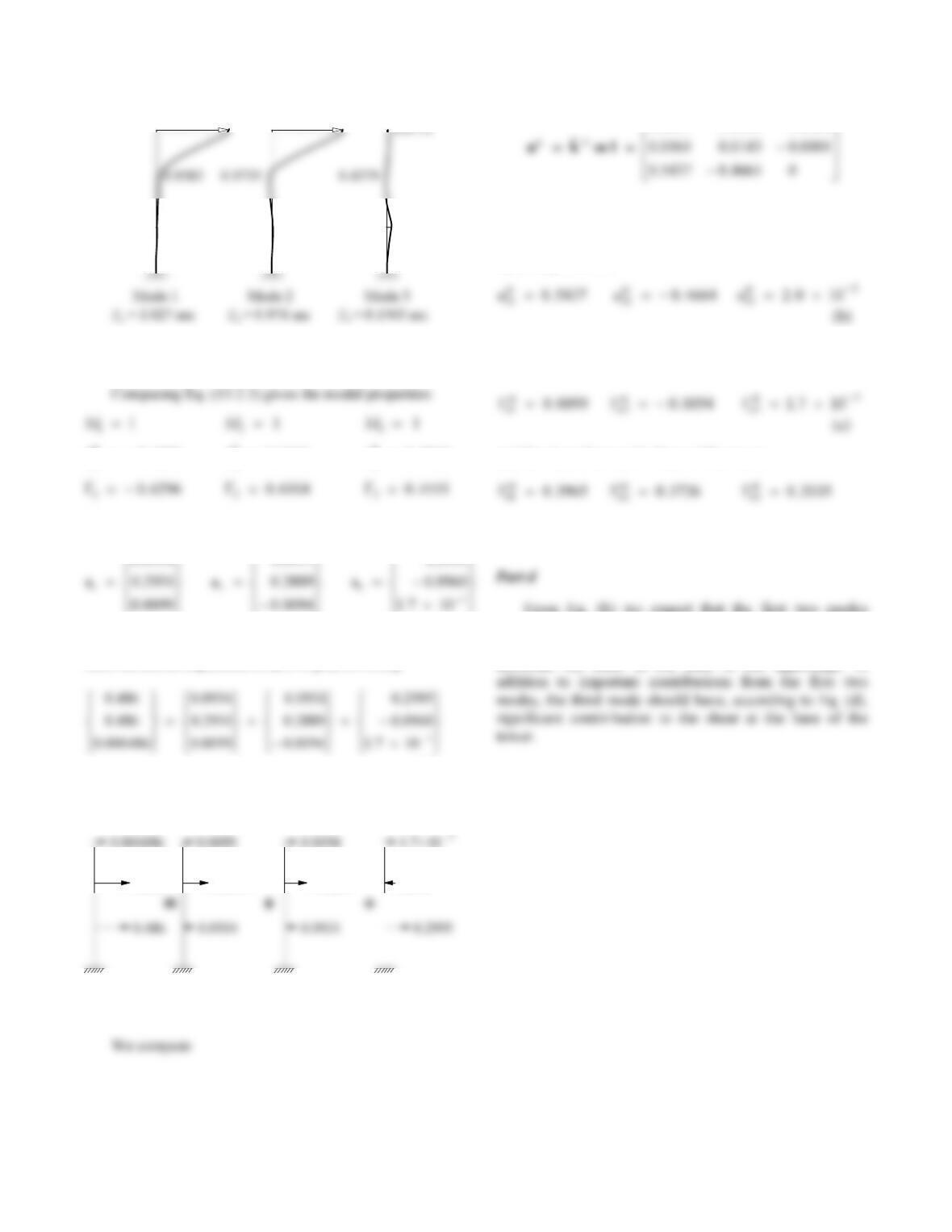
Solution of the eigenvalue problem gives the natural
periods and modes:
The modes have been normalized so that
41
32.34
0.3054
31.80
0.3139
1.366
Part b
Lh
10 6296 . Lh
20 6104. Lh
30 4511.
Substituting these data in Eq. (13.2.4) gives
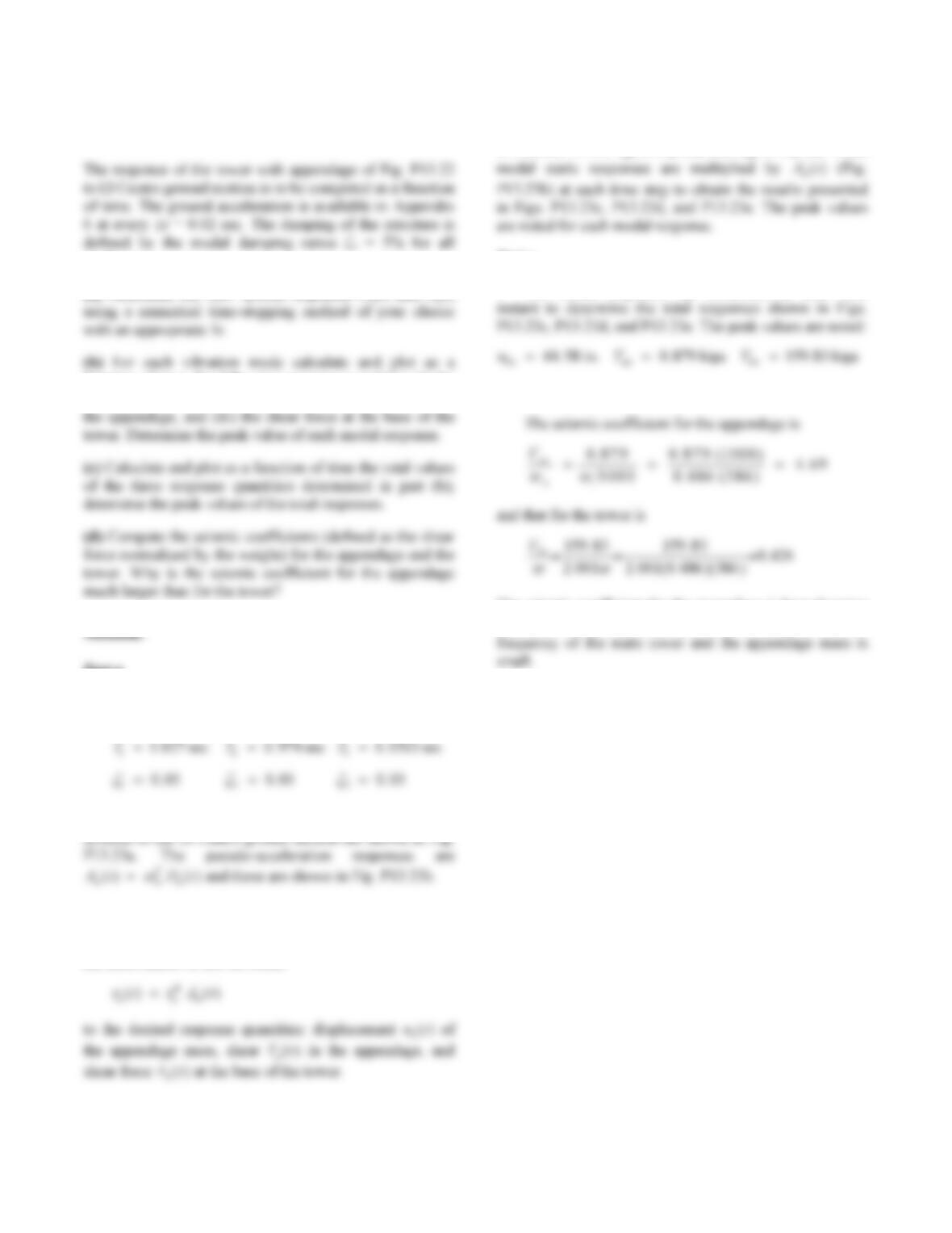
Thus the modal expansion of m1 is [Eq. (13.2.2)]:
(a)
This expansion is shown graphically:
0.486 0.2931 0.2889
0.096
Part c
0.0051 0.0046 0.0004
The modal static responses of the displacement of the
appendage mass are
Static analysis of the system for forces sn (n = 1, 2, and 3)
gives the shear force in the appendage:
and the shear force at the base of the tower:
(d)
From Eq. (b) we expect that the first two modes
should give the largest contribution to the displacement of
the appendage mass. Similarly, these two modes will
dominate the shear at the base of the appendage. In
42
Problem 13.23
modes.
(a) Determine the SDF system responses Dn(t) and An(t)
function of time the following response quantities: (i) the
displacement of the appendage mass, (ii) the shear force in
Part a
The three modal SDF systems have the following
properties:
T
T
T
The displacement responses D
t
n() of these three SDF
Part b
Step 5c of Section 13.2.4 is implemented to determine
the contribution of the nth mode
t
t
The modal static responses un3
st are available in Eq. (b)
of Problem 13.22, Van
st in Eq. (b), and Vbn
st in Eq. (c). These
Part c
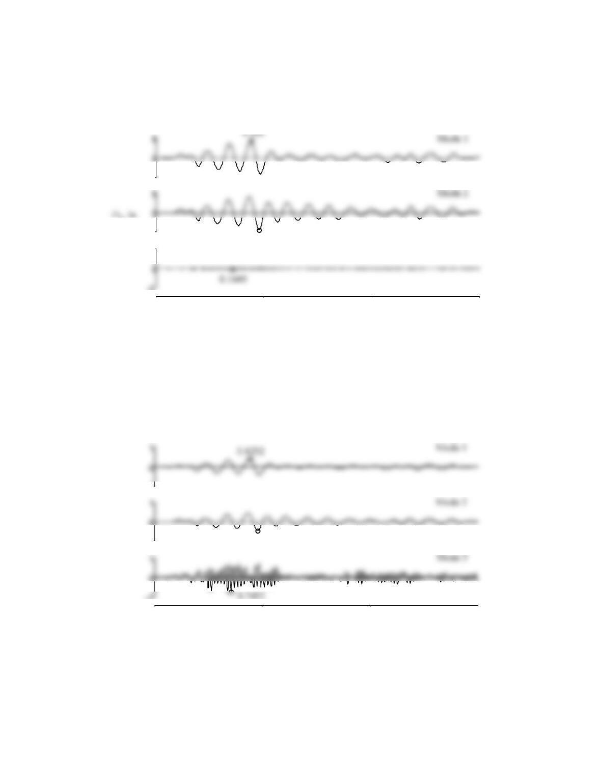
The modal responses are combined at each time
Part d
The seismic coefficient for the appendage is large because
its natural frequency is tuned to the fundamental natural
A
t
43
-5
-5
4.531
-5
5 Mode 3
Time, sec
0 5 10 15
Fig. P13.23a
-1
-1
0.4879
-1
0 5 10 15
Time, sec
Fig. P13.23b
Figure P13.23a
Figure P13.23b
44
-100
-100
100
87.93
-100
100 Mode 3
Mode 2
0 5 10 15
-100
100
44.58
Total
Time, sec
Fig. P13.23c
-2
-2
-2
0.879
0 5 10 15
-2
0.0049
Time, sec
Fig. P13.23d
Figure P13.23c
Figure P13.23d
45
-100
100
64.83
70. 23
-200
159.83
Mode 2
0 5 10 15
-100
58. 59
52
Problem 13.24
natural vibration frequencies and modes were to be
determined in Problem 10.24) is excited by ground motion
(a) Expand the effective earthquake forces in terms of their
modal components and show this expansion graphically.
system to a 3N-DOF system, is satisfied.
An(t).
Solution:
Data (see Problem 9.14):
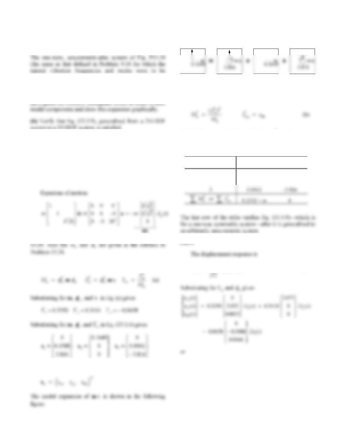
Equations of motion:
02.071 0
Part a
Substituting for m,
n and in Eq. (a) gives
Substituting for m,
n, and n in Eq. (13.1.6) gives
where
The modal expansion of m is shown in the following
figure:
Part b
Mode Mn
* IOn
*
53
Part c
The displacements due to the nth mode are
Substituting for n and
n gives
or
Part d
The modal static responses for base shear in the
y-direction and base torque are
Substituting numerical values for
s
yn and
s
n
gives
Substituting
V
byn
st and Tbn
st in Eq. (13.3.15) gives the modal
responses:
Vt
A
t
by11
0 2245() . ()
t
A
t
T
t
A
t
T
t
T
A
t
b33
Combining the modal responses gives the total response:
A
A
T
t
A
t
A
t
54
Problem 13.25
determined in Problem 10.24) is excited by ground motion
u
g(t) along the diagonal d–b. Formulate the equations of
motion for this 3DF system and:
system to a 3N-DOF system, is satisfied.
(c) Determine the displacement uy and rotation uθ of the
slab in terms of Dn(t).
(d) Determine the x and y components of the base shear
and base torque in terms of An(t).
Solution:
where m, b, and k are given in the solution to Problem
Part a
where
0.1649
0.1588
0.0061
Part b
From Eq. (13.3.10),
Substituting numerical data for
M
n, Ln
h, and
s
n
gives
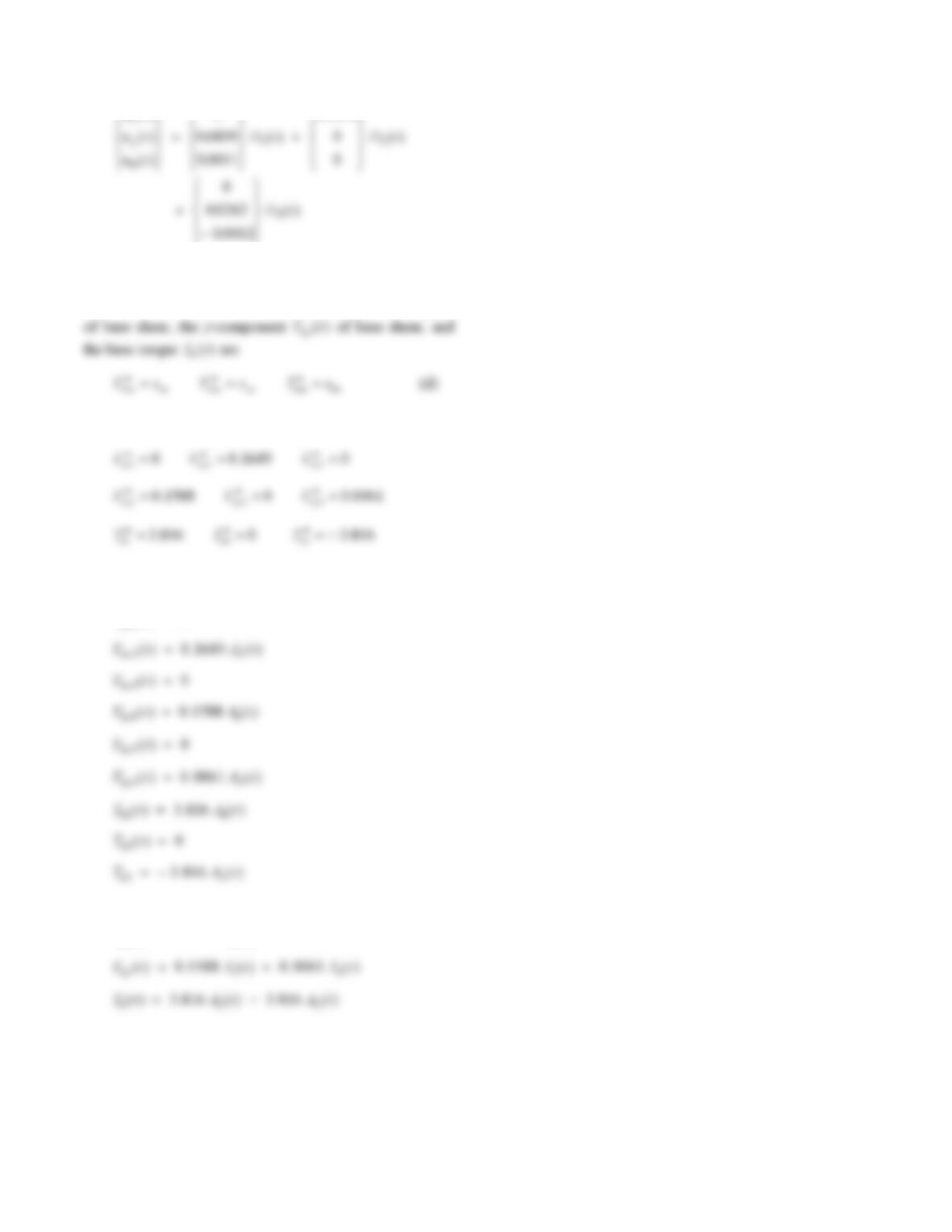
Table P13.25.
Table P13.25
Mode Mn
* IOn
*
1 0.1123 3.816
2 0.1166 0
u() ()tDt
nn n
3
(c)
55
ut
()
.
R
U
R
U
R
U
T
W
0
07071
Part d
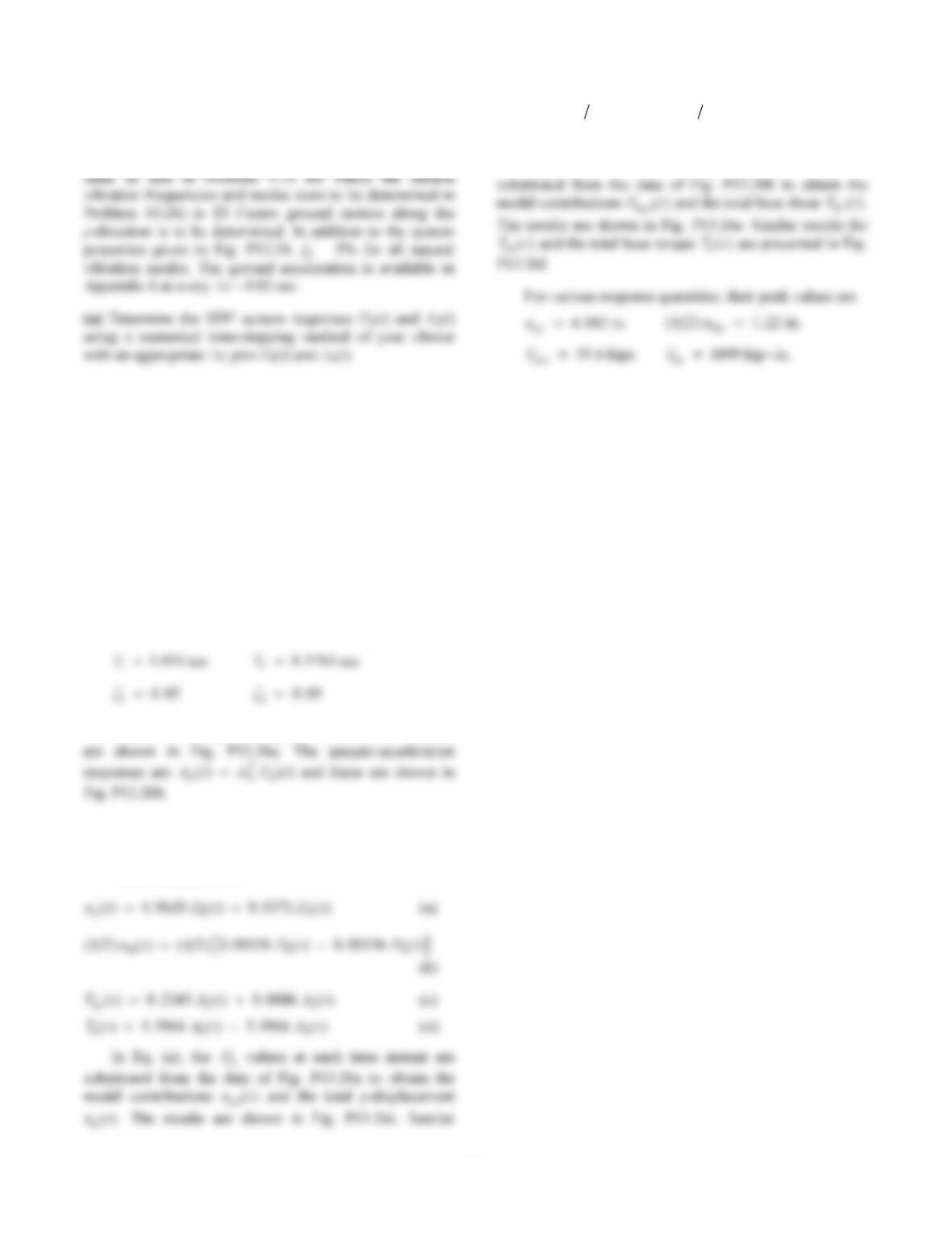
The modal static responses for the x-component V
t
bx ()
T
t
Substituting numerical values for
s
x
n,
s
yn , and
s
n
gives
Substituting these modal static responses in Eq. (13.3.15)
gives the modal responses:
V
t
bx10()
t
A
t
t
A
t
t
A
t
T
t
A
t
T
t
T
A
t
Combining the modal responses gives the total response:
V
t
A
t
bx () . ()0 1649 2
A
A
T
t
A
t
A
t
56
Problem 13.26
The response history of the system of Problem 13.24 (the
(b) For each vibration mode, calculate and plot as a
function of time the following response quantities: uy,
/2
u
b
, base shear Vb, and base torque Tb.
(c) Calculate and plot as a function of time the total
responses; determine the peak values of the total
responses.
Solution:
Part a
Ground motion in the y-direction excites the first and
third natural vibration modes of the system. The
corresponding SDF systems have the following properties:
T
T
The displacement responses D
t
n() of the two SDF systems
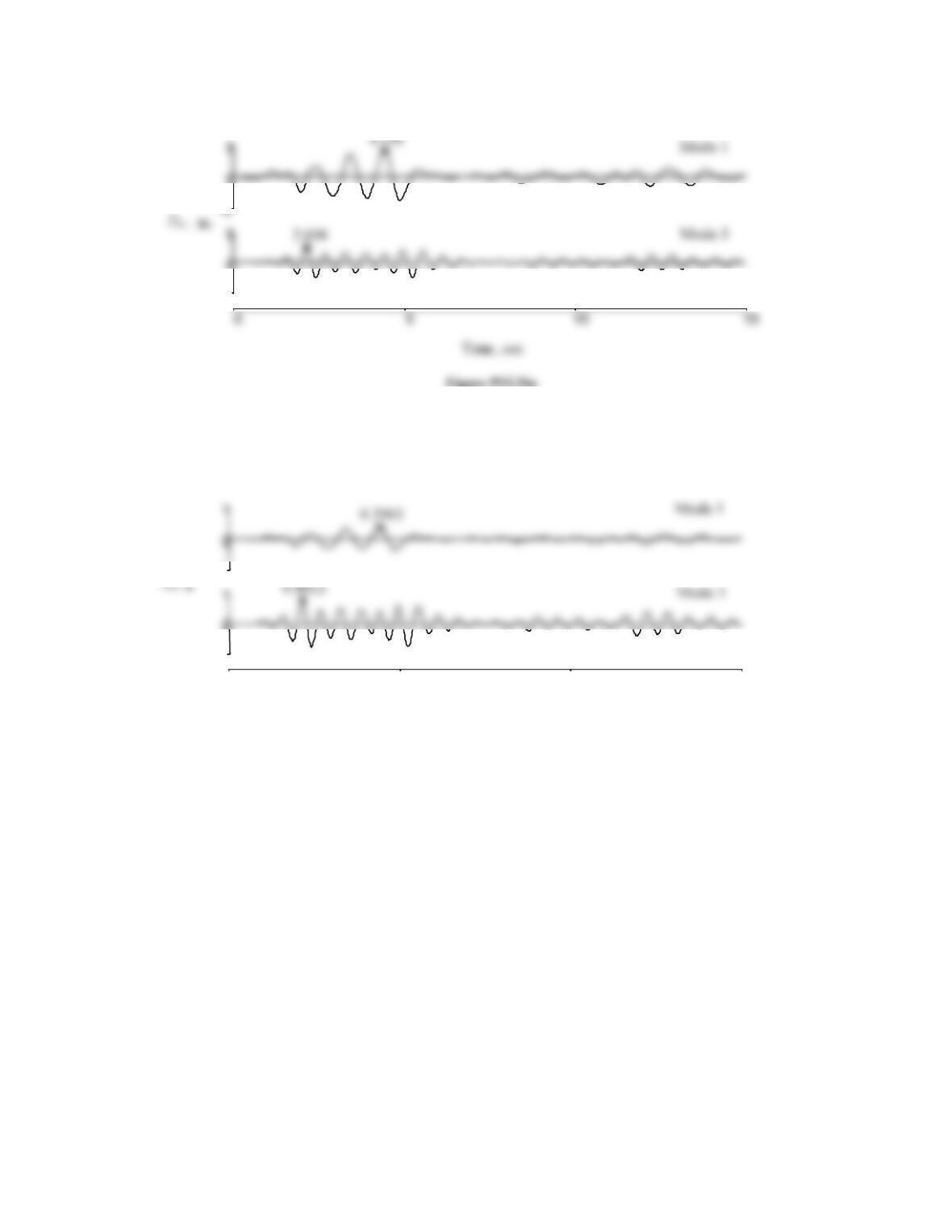
Parts b and c
From Problem 13.24,
t
t
t
t
A
t
A
t
T
t
A
t
A
t
results for ()()bu
t
n
2
and ()()bu
t
2
are presented in
Fig. P13.26d.
In Eq. (c), the
A
n values at each time instant are
T
t
T
t
T
57
-5
-1
-1
0 5 10 15
Time, sec
Fig. P13.26b
Figure P13.26b