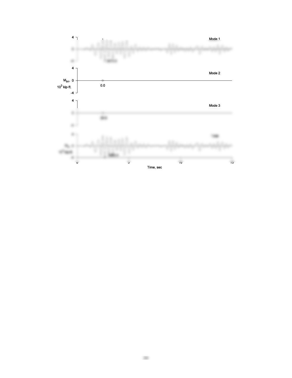
Figure P13.8e
21
Problem 13.9
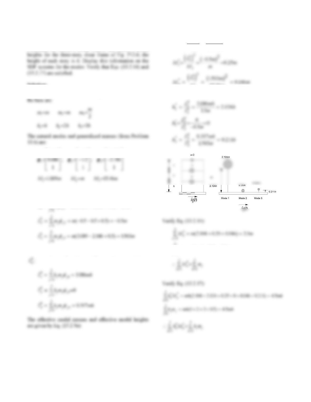
SDF systems for the modes. Verify that Eqs. (13.2.14) and
(13.2.17) are satisfied.
Solution:
The natural modes and generalized masses (from Problem
13.5) are:
Lmm m
h
jj
j
22
1
3
11005105
() . .
Substituting for mj, hj, and
jn in Eq. (13.2.9b) gives Ln
:
Lhm
jjj
j
33
1
3
The effective modal masses and effective modal heights
are given by Eq. (13.2.9a):
22
( ) (1.866) 2.3213
h
Lm
M
3
3
15 0 0121
..
h
u (t)
g
=
u (t)
g
h
2h
0.1667 m
m
2h
h
Mmmmm
n
n
1
2 3213 0 1667 0 0121 2 5
3
22
Verify Eq. (13.2.17):
hM h m h m h m
nn
n
** (. ) ( )(. ) (. )
1
3
2 2 3123 0 1667 2 0 0120
23
Problem 13.10
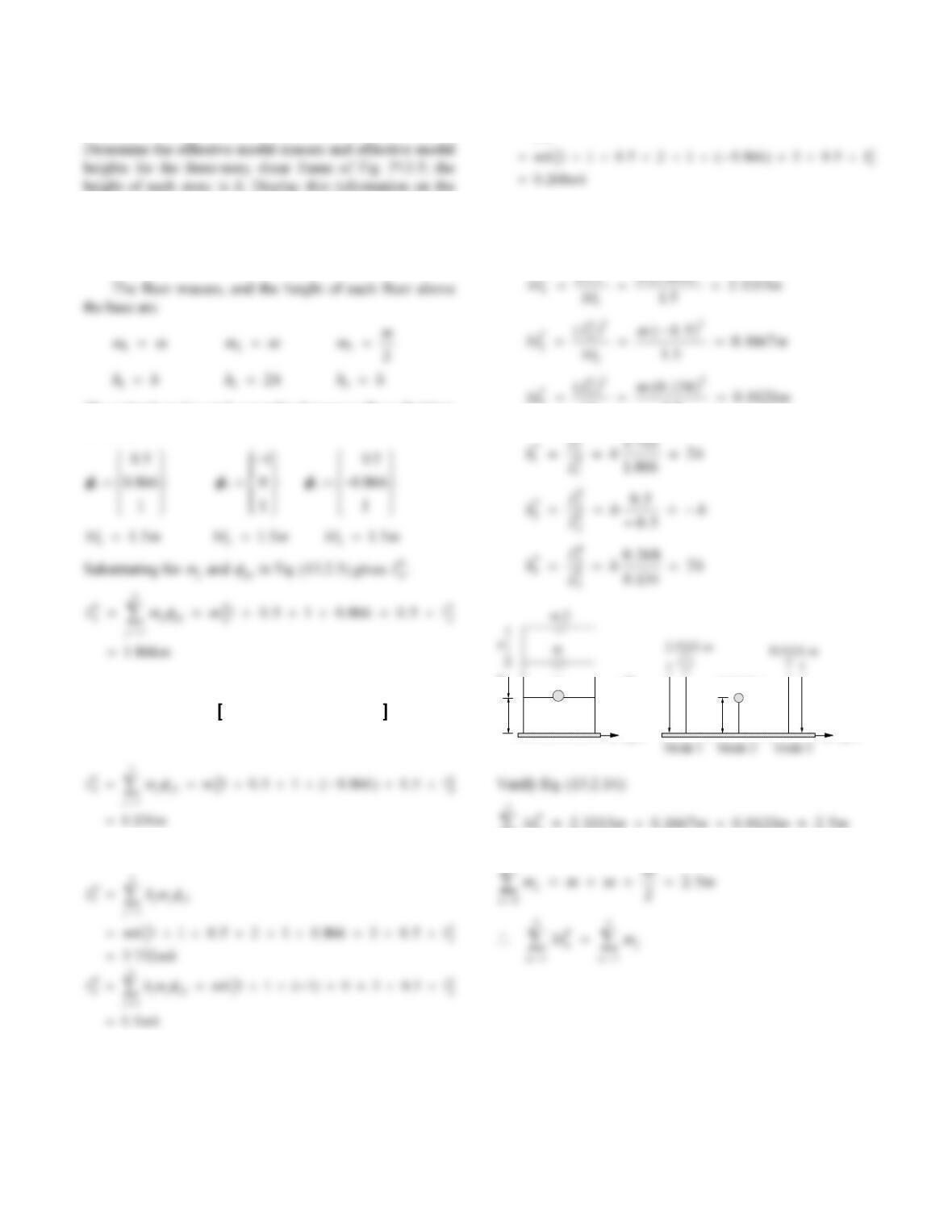
Determine the effective modal masses and effective modal
Solution:
The floor masses, and the height of each floor above
0 314
L
O
.
12
L
O
/
3189
L
O
.
Substituting for
m
j and
jn in Eq. (13.2.3) gives Ln
h:
Lm m m
h
3
0314 0686 05 15
(. . .) .
Substituting for mj, hj, and
j
n
in Eq. (13.2.9b) gives
M
L
M
m
mm
M
mm
h
1
1
2
1
3
3
15 2
1069 2104
15 46 0146
*
.
..
..
ej bg
mm m
j
j
(.).
1
3
1105 25
24
Problem 13.11
of this three-story frame to horizontal ground motion ݑሷ g(t).
Express (a) the floor displacements and joint rotations in
u1
u3
h
m/2
m
.. .
L
O
40 85 23 26 511
13
1 4576.EI
mh
23
4 7682.EI
mh
0.3156 0.7409 1.2546
From Eq. (13.2.3), for the first mode:
Lmm
mm
h
10 3156 0 7451 1 215607
F
H
GI
K
J.. .
Computed similarly, these quantities for the second and
third modes are
Part a
(a)
The joint rotations associated with u1 are
0 1084 0 5342 0 0774
0 4625
…
.
M
M
M
P
P
P
R
U
25
R
U
0 4796
.
Similarly, the floor displacements due to the second and
third modes are
(d)
The joint rotations associated with u2 and u3 can be
computed following Eq. (b):
01772
.
R
U
00916
.
R
U
ut Dt Dt Dt
112 3
0 4265 0 3766 01968
() . () . () . ()
U
Part b
The bending moments at the ends of a flexural element
b
4
u
=
Figure P13.11b
Substituting these ua, ub,
a, and
b, and Eqs. (g)–(h) in
Eqs. (i) and (j) gives
MEI
1 5999 1 9054 1 3643.(). ().()
Mmh At At At
a
0 7526 0 08381 0 02030
12 3
.(). (). ()
26
b
u = 0
a
u = 0
Figure P13.11c
Substituting these ua, ub,
a, and
b, and Eqs. (g)–(h) in
Eqs. (i) and (j) gives
M
M
ab
Problem 13.12
Figure P13.12 shows three-story frames (the same as those
in Problems 9.10 and 10.20) together with flexural rigidity
for beams and columns. Determine the dynamic response
of this three-story frame to horizontal ground motion ݑሷ g(t).
Express (a) the floor displacements and joint rotations in
Figure P13.12a
Mass and lateral stiffness matrices (from Problem
486.568.2238.39
Natural frequencies and modes (from Problem 10.20):
12 3
0.273 0.706 1.529
0.698 0.441 1.315
11 1
(b)
From Eq. (13.2.3), the modal properties are:
First Mode:
1
Computed similarly, these quantities for the second and
third modes are
M
3
Part a
From Eq. (13.2.5) the floor displacements due to the
first mode are:
The joint rotations associated with u1 are
where T was determined in solving Problem 10.20.
Thus:
925.0131.12612.0
0962.06084.01512.0
469.0
1
u
2
u
3
u
8
u
9
h
28
Similarly, the floor displacements due to the second and
third modes are
The joint rotations associated with u2 and u3 can be
computed following Eq. (b):
256.0
104.0
Combining modal responses gives the total floor
displacements:
ut Dt Dt Dt
112 3
0 377 0 383 0 238
() . () . () . ()
Combining modal contributions to joint rotations gives
uu u u
0010203
() () () ()tttt (j)
Part b
The bending moments at the ends of a flexural element
are related to the nodal displacements by:
For a first story column, hL and the nodal displace-
ments are shown in Fig. P13.12b:
Figure P13.12b
For the second floor beam, hL 2 and the nodal dis-
placements are shown in Fig. P13.12c:
MMEI
hDt D t Dt
ab
2123
1 407 0 717 0 615.(). ().()
2 and
u
a
0
a0
ub0
ua
0
2h
29
Problem 13.13
for beams and columns. Determine the dynamic response
Figure P13.13a
32.67 14.58 2.172
0.225
0.536
3.083
From Eq. (13.2.3), the modal properties are:
Computed similarly, these quantities for the second and
third modes are
Part a
From Eq. (13.2.5) the floor displacements due to the
first mode are:
The joint rotations associated with 1
u are
where T was determined in solving Problem 10.21. Thus:
0.3117 0.3643 0.0350
0.2172 0.9597 0.7846
u
2
u
3
u8u9
2h
h
Similarly, the floor displacements due to the second and
third modes are
10.556
The joint rotations associated with 2
u and 3
u can be
computed following Eq. (b):
M
0.235
0.235
0.029
0.029
Combining modal responses gives the total floor
displacements:
Combining modal contributions to joint rotations gives
0010203
() () () ()ttttuu u u
(j)
Part b
(l)
Figure P13.13b
(
12 3
2
0.4223 ) 0.8481 ( ) 2.1657 ( )
b
EI
M
Dt D t D t
h
123
a
123
0.2556 ( ) 0.0698 ( ) 0.0511 ( )
b
M
mh A t A t A t
h
MEI
L
EI
L
EI
L
uEI
L
u
babab
246
2
6
2
u
a
0
a0
a
au
6
bu7
ab
2h