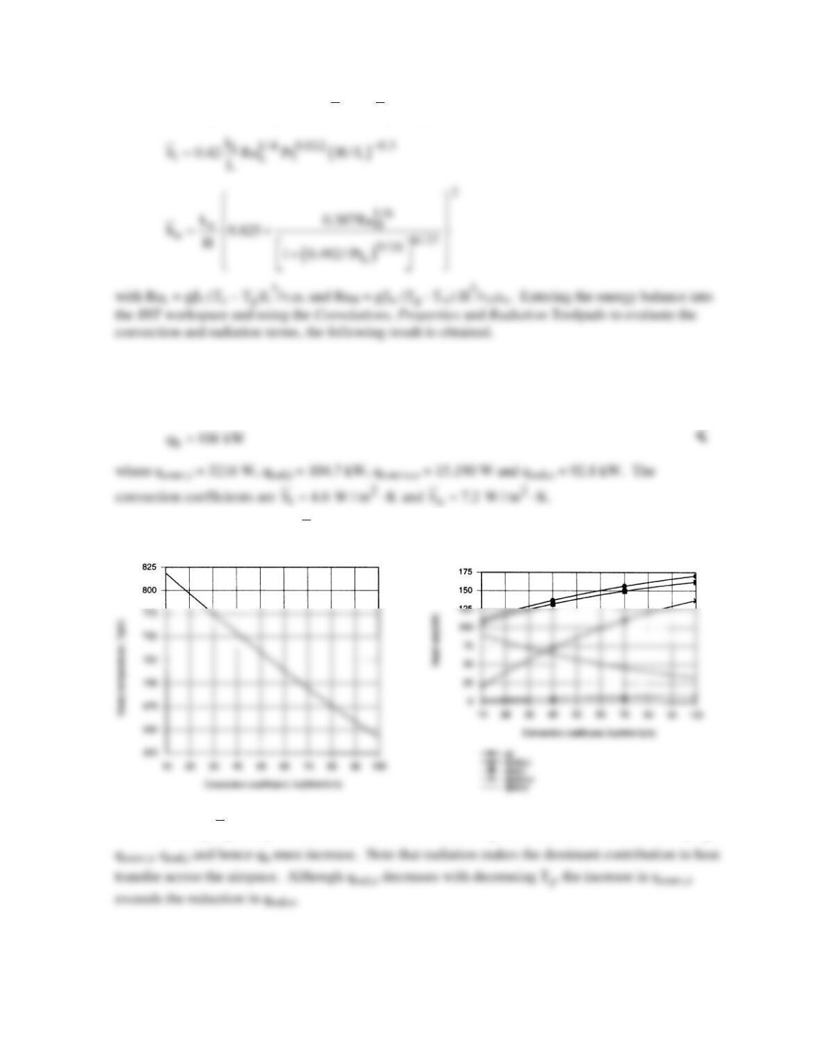
PROBLEM 13.91 (Cont.)
where, assuming
47
L io
10 Ra 10 , h and h≤≤
are given by Eqs. 9.52 and 9.26, respectively,
g
T 825 K=
<
The corresponding value of qh is
(c) For the prescribed range of
o
h,
IHT was used to generate the following results.
With increasing
o
h,
the glass is cooled more effectively and Tg must decrease. With decreasing Tg,
PROBLEM 13.92
KNOWN: Spectral distribution of the absorption coefficient of pure solid silicon.
FIND: (a) The total absorption coefficient for pure solid silicon subject to irradiation from a source at
the melting point temperature of silicon. (b) Estimates of the total transmissivity, total absorptivity and
total emissivity of a L = 140
m
m thick silicon sheet.
ASSUMPTIONS: (1) Irradiation from large surroundings, (2) Kirchoff’s law assumed to be valid.
PROPERTIES: Table A-1, Silicon: Tf = 1685 K.
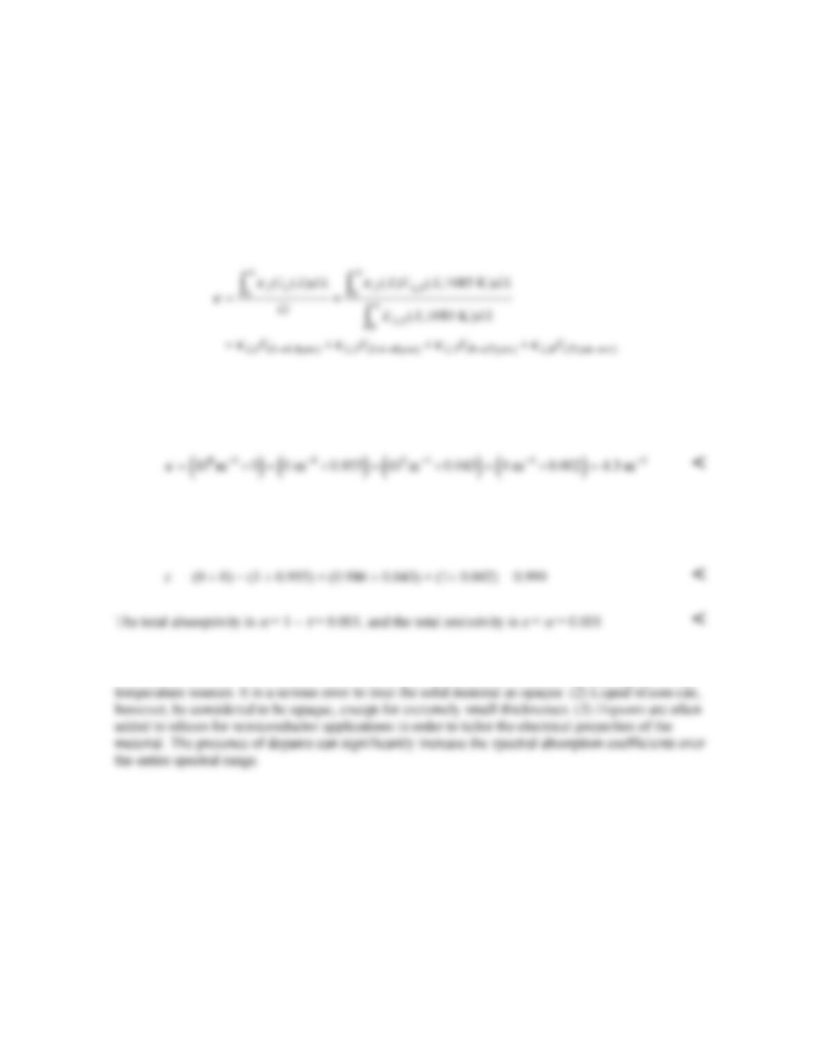
ANALYSIS: Treating the irradiation from the large surroundings as black, we have
From Table 12.2, F(0 → 0.4
m
m⋅1685K) ≈ 0, F(0.4
m
m⋅1685K→8
m
m⋅1685K) = 0.955, F(8
m
m⋅1685K→15
m
m⋅1685K) = 0.998 –
0.955 = 0.043, F(15
m
m⋅1685K→∞) = 1 – 0.998 = 0.002. Therefore,
(b) The spectral transmissivity is
L
e
λ
κ
λ
τ
−
=
which, for L = 140
m
m, gives
τλ
,1 = 0,
τλ
,2 = 1,
τλ
,3 =
0.986,
τλ
,4 = 1. Hence,
COMMENTS: (1) Solid silicon is almost perfectly transparent to irradiation emanating from high
PROBLEM 13.93
KNOWN: Conditions associated with a spherical furnace cavity.
FIND: Cooling rate needed to maintain furnace wall at a prescribed temperature.
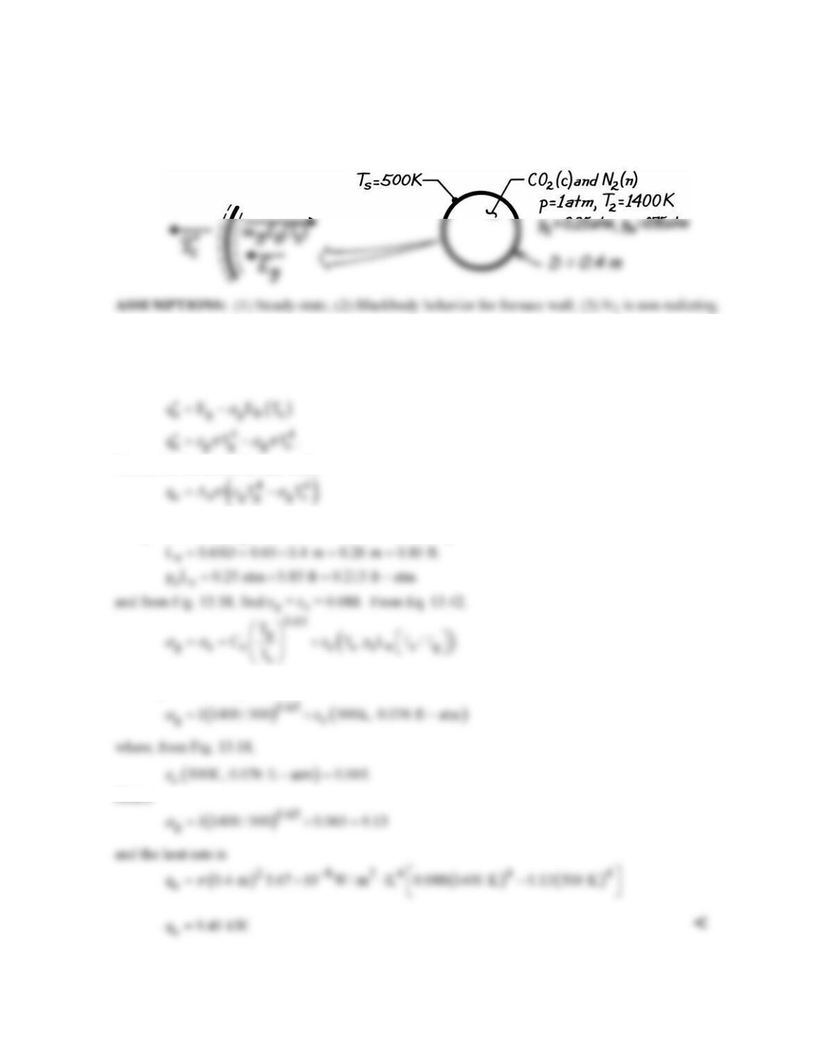
SCHEMATIC:
ANALYSIS: From an energy balance on a unit surface area of the furnace wall, the cooling rate per
unit area must equal the absorbed irradiation from the gas (Eg) minus the portion of the wall’s
emissive power absorbed by the gas
Hence, for the entire furnace wall,
The gas emissivity, εg, follows from the mean beam length of Table 13.4
With Cc = 1 from Fig. 13.19,
Hence
PROBLEM 13.94
KNOWN: Diameter and gas pressure, temperature and composition associated with a gas turbine
combustion chamber.
FIND: Net radiative heat flux between the gas and the chamber surface.
SCHEMATIC:
ASSUMPTIONS: (1) Steady-state conditions, (2) Blackbody behavior for chamber surface, (3)
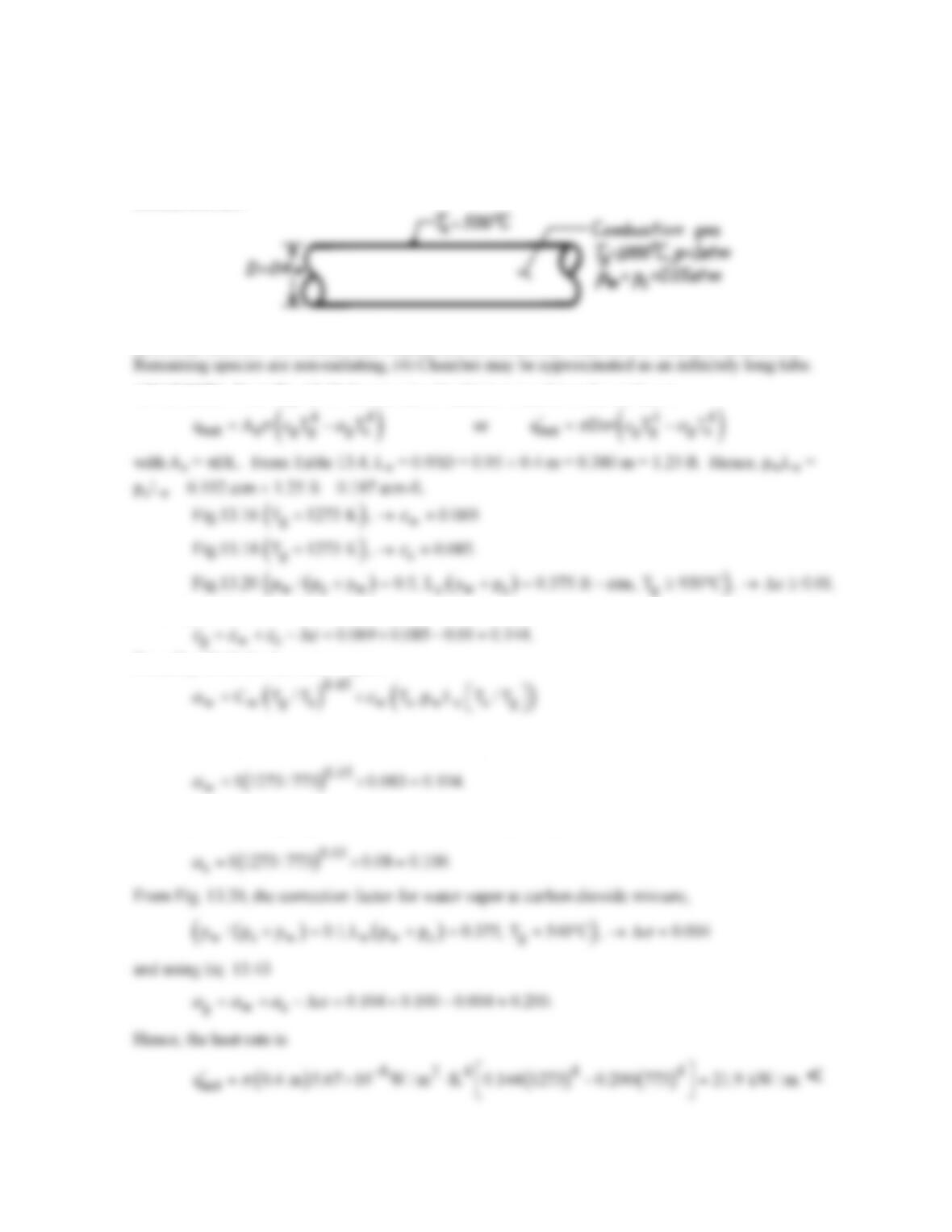
ANALYSIS: From Eq. 13.40 the net rate of radiation transfer to the surface is
From Eq. 13.38,
From Eq. 13.41 for the water vapor,
where from Fig. 13.16 (773 K, 0.114 ft-atm), → εw ≈ 0.083,
From Eq. 13.42, using Fig. 13.18 (773 K, 0.114 ft-atm), → εc ≈ 0.08,
PROBLEM 13.95
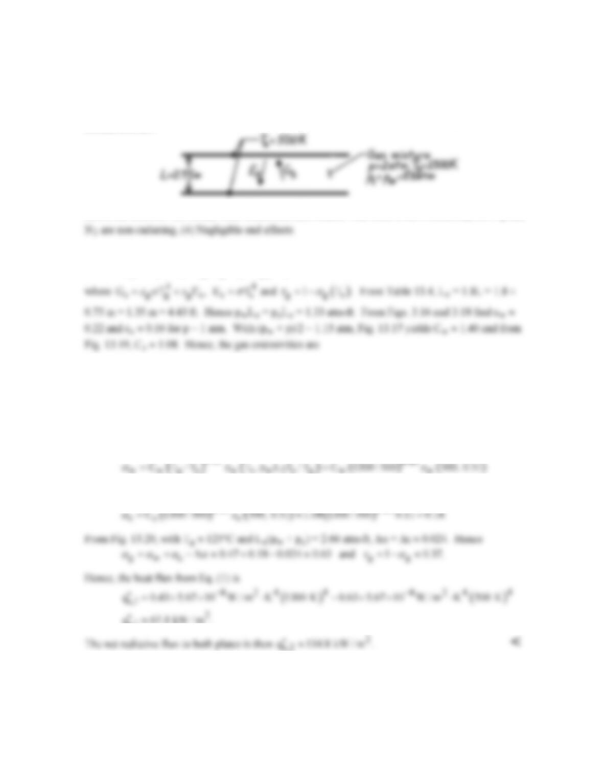
KNOWN: Pressure, temperature and composition of flue gas in a long duct of prescribed diameter.
FIND: Net radiative flux to the duct surface.
SCHEMATIC:
ASSUMPTIONS: (1) Steady-state conditions, (2) Duct surface behaves as a blackbody, (3) Other
ANALYSIS: With As = pDL, it follows from Eq. 13.40 that
()
44
net g g g s
q DT T
p σε α
′= −
From Table 13.4, Le = 0.95D = 0.95 × 1 m = 0.95 m = 3.12 ft. Hence
With Tg = 1400 K, Fig. 13.16 → εw = 0.083; Fig. 13.18 → εc = 0.072. With pw/(pc + pw) = 0.67,
From Eq. 13.42,
( ) ( )
0.45
C T /T T , p L T /T
αε
=
×
Hence from Eq. 13.43,
PROBLEM 13.96
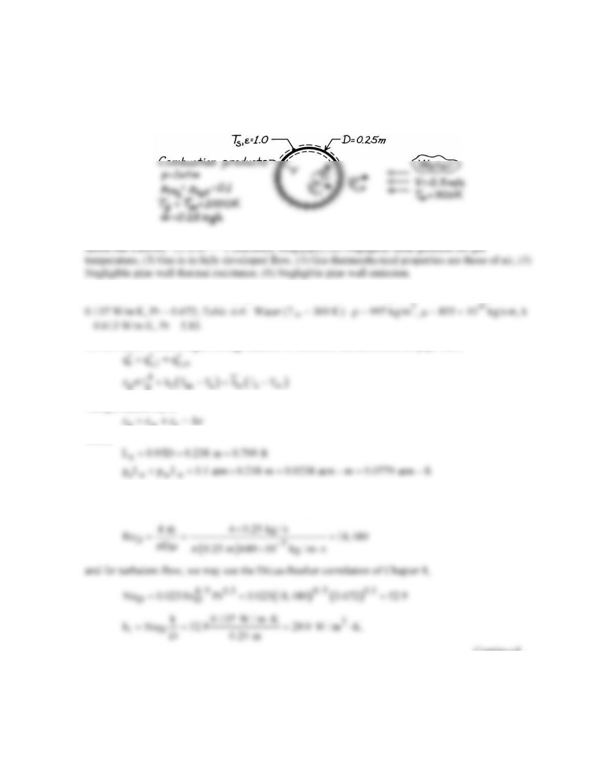
KNOWN: Gas mixture of prescribed temperature, pressure and composition between large parallel
plates of prescribed separation.
FIND: Net radiation flux to the plates.
SCHEMATIC:
ASSUMPTIONS: (1) Steady-state conditions, (2) Furnace wall behaves as a blackbody, (3) O2 and
ANALYSIS: The net radiative flux to a plate is
( )
44
s,1 s s g g g s
q GE T 1 T
εσ τ σ
′′ = − = −−
( ) ( )
w ww c cc
C 1 atm 1.40 0.22 0.31 C 1 atm 1.08 0.16 0.17.
ε ε εε
= ≈×= = ≈×=
From Fig. 13.20 with pw/(pc + pw) = 0.5, Le(pc + pw) = 2.66 atm-ft and Tg > 930°C, ∆ε ≈ 0.047.
Hence, from Eq. 13.38,
g wc
0.31 0.17 0.047 0.43.
εεε ε
= + −∆ ≈ + − ≈
To evaluate αg at Ts, use Eq. 13.43 with
0.45 0.45
( )
0.45
w
1.40 1300 / 500 0.22 0.47
α
≈=
0.45 0.45
s,1
q 67.4 kW / m .
PROBLEM 13.97
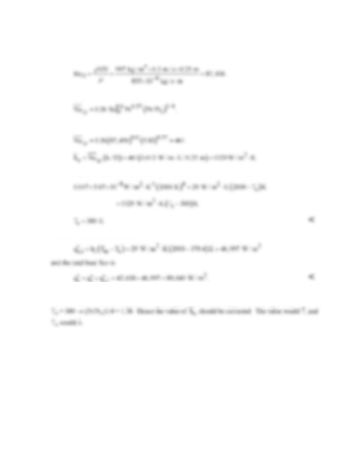
KNOWN: Flow rate, temperature, pressure and composition of exhaust gas in pipe of prescribed
diameter. Velocity and temperature of external coolant.
FIND: Pipe wall temperature and heat flux.
SCHEMATIC:
PROPERTIES: Table A-4: Air (Tm = 2000 K, 1 atm): ρ = 0.174 kg/m3, m = 689 × 10-7 kg/m⋅s, k =
ANALYSIS: Performing an energy balance for a control surface about the pipe wall,
The gas emissivity is
g wc
where
and from Fig. 13.16 → εw ≈ 0.017; Fig. 13.18 → εc ≈ 0.031; Fig. 13.20 → ∆ε ≈ 0.001. Hence εg =
0.047. Estimating the internal flow convection coefficient, find
Continued …
PROBLEM 13.97 (Cont.)
Estimating the external convection coefficient, find
Hence, using the Zukauskas correlation of Chapter 7,
Assuming Pr/Prs ≈ 1,
Substituting numerical values in the energy balance, find
The heat flux due to convection is
COMMENTS: Contributions of gas radiation and convection to the wall heat flux are approximately
the same. Small value of Ts justifies neglecting emission from the pipe wall to the gas. Prs = 1.62 for
PROBLEM 13.98
KNOWN: Flow rate, temperature, pressure and composition of combustion gas that is subsequently
mixed with saturated steam of known flow rate.
FIND: Gas emission to a pipe wall with and without steam injection.
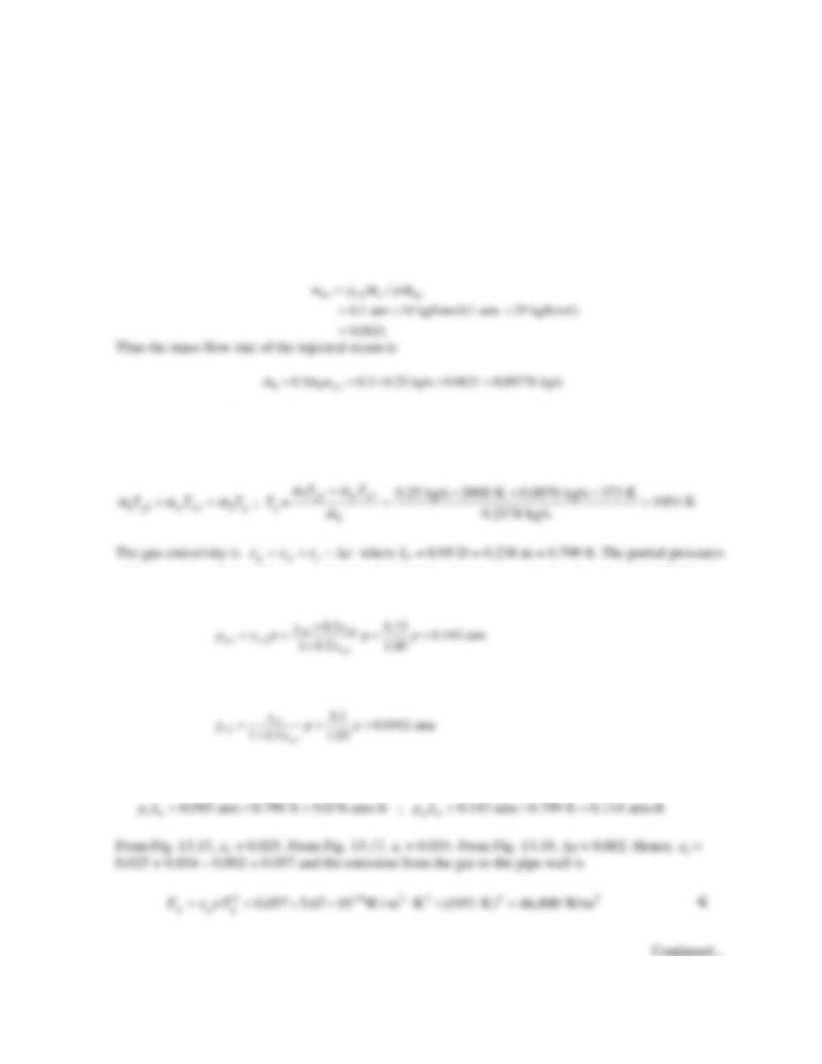
ASSUMPTIONS: (1) Gas thermophysical properties and molecular weight same as air, (2) ideal gas
mixture.
ANALYSIS: The mass flow rate without steam injection is
10.25 kg/sm=
. The mass flow rate of
water vapor in the original mixture is
11w
mm
where mw1 is the mass fraction of water vapor,
and the total mass flow rate after injection is
2 1S
0.2578 kg/sm mm=+=
. Treating the gases as ideal
with properties of air, an energy balance on the mixing of the combustion products and injected steam
yields
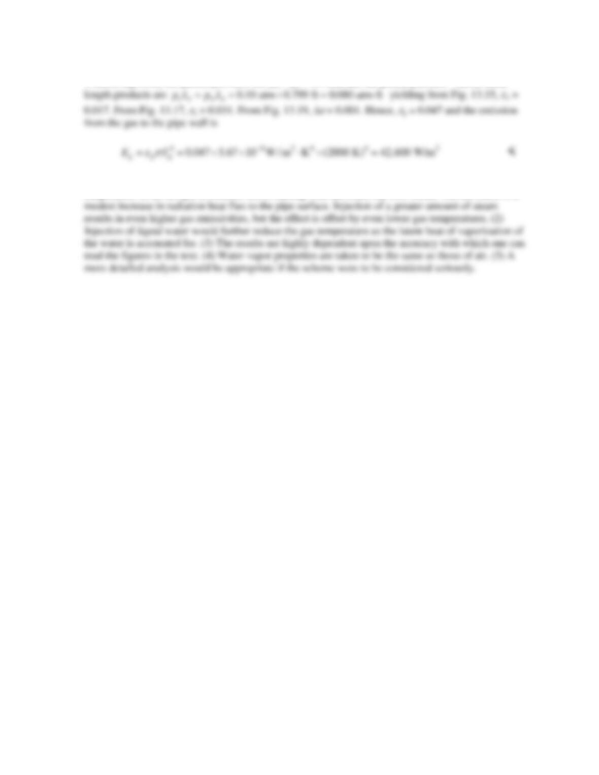
of the gases are obtained by accounting for the additional water vapor in the pipe relative to Problem
13.97.
where xw2 is the mole fraction of water in the final mixture. Similarly,
The products of the partial pressures and mean beam lengths are therefore
PROBLEM 13.98 (Cont.)
Without injection, the partial pressures are pw = pc = 0.1 atm and the partial pressure – mean beam
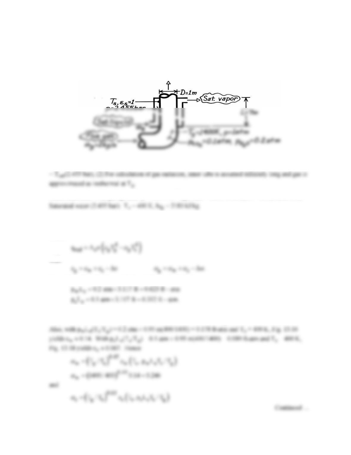
COMMENTS: (1) The gas emissivity is increased significantly with steam injection, but the
temperature of the hot gas is reduced due to mixing with the relatively cool steam. The net effect is a
PROBLEM 13.99
KNOWN: Flowrate, composition and temperature of flue gas passing through inner tube of an
annular waste heat boiler. Boiler dimensions. Steam pressure.
FIND: Rate at which saturated liquid can be converted to saturated vapor,
s
m.
SCHEMATIC:
ASSUMPTIONS: (1) Inner wall is thin and steam side convection coefficient is very large; hence Ts
PROPERTIES: Flue gas (given): m = 530 × 10-7 kg/s⋅m, k = 0.091 W/m⋅K, Pr = 0.70; Table A-6,
ANALYSIS: The steam generation rate is
( )
s fg conv rad fg
m q/h q q /h= = +
where
From Table 13.4, find Le = 0.95D = 0.95 m = 3.117 ft. Hence
From Fig. 13.16, find εw ≈ 0.13 and Fig. 13.18 find εc ≈ 0.095. With pw/(pc + pw) = 0.67 and Le(pw
+ pc) = 0.935 ft-atm, from Fig. 13.20 find ∆ε ≈ 0.036 ≈ ∆α. Hence εg ≈ 0.13 + 0.095 – 0.036 = 0.189.
PROBLEM 13.99 (Cont.)
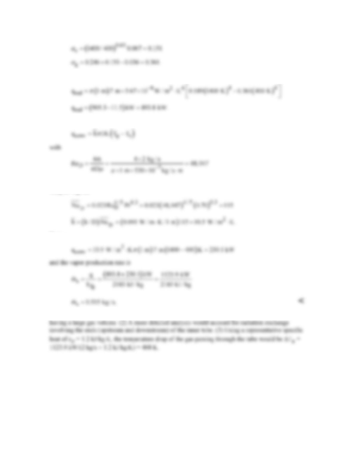
Hence
For convection,
and assuming fully developed turbulent flow throughout the tube, the Dittus-Boelter correlation of
Chapter 8 gives
Hence
COMMENTS: (1) Heat transfer is dominated by radiation, which is typical of heat recovery devices
PROBLEM 13.100
KNOWN: Wet newsprint moving through a drying oven.
FIND: Required evaporation rate, air velocity and oven temperature.
SCHEMATIC:
ASSUMPTIONS: (1) Steady-state conditions, (2) Negligible freestream turbulence, (3) Heat and
PROPERTIES: Table A-6, Water vapor (300 K, 1 atm): ρsat = 1/vg = 0.0256 kg/m3, hfg = 2438
ANALYSIS: The evaporation rate required to completely dry the newsprint having a water content
of
2
A
m 0.02 kg / m
′′ =
as it enters the oven (x = L) follows from a species balance on the newsprint.
The rate at which moisture enters in the newsprint is
The required velocity of the airstream through the oven, u∞, can be determined from a convection
analysis. From the rate equation,
PROBLEM 13.100 (Cont.)
and, from Section 7.2.1 for laminar flow
However, since ReL > ReLc = 5 × 10⁵, the flow must be turbulent. Using the correlation for mixed
laminar and turbulent flow conditions from Section 7.2.3, find
noting ReL > ReLc. Recognize that
u∗
∞
is the velocity relative to the newsprint,
where
1 2 21 1 12 2 21
hence, with ε1 = 0.8,
PROBLEM 13.101
KNOWN: Configuration of grain dryer. Emissivities of grain bed and heater surface. Temperature
of grain.
FIND: (a) Temperature of heater required for specified drying rate, (b) Convection mass transfer
coefficient required to sustain evaporation, (c) Validity of assuming negligible convection heat
transfer.
SCHEMATIC:
ASSUMPTIONS: (1) Diffuse/gray surfaces, (2) Oven wall is a reradiating surface, (3) Negligible
PROPERTIES: Table A-6, saturated water (T = 330 K): vg = 8.82 m3/kg, hfg = 2.366 × 10⁶ J/kg.
ANALYSIS: (a) Neglecting convection, the energy required for evaporation must be supplied by net
radiation transfer from the heater plate to the grain bed. Hence,
where
A′
= R = 1 m, Fpg = 0 and FpR = FgR = 1. Hence,
(b) The evaporation rate is given by Eq. 6.12, and with
s A evap
A 1 m, n m ,
′ ′′
= =
and ρA,∞ = 0,
Continued …
PROBLEM 13.101 (Cont.)
(c) From the heat and mass transfer analogy, Eq. 6.60,
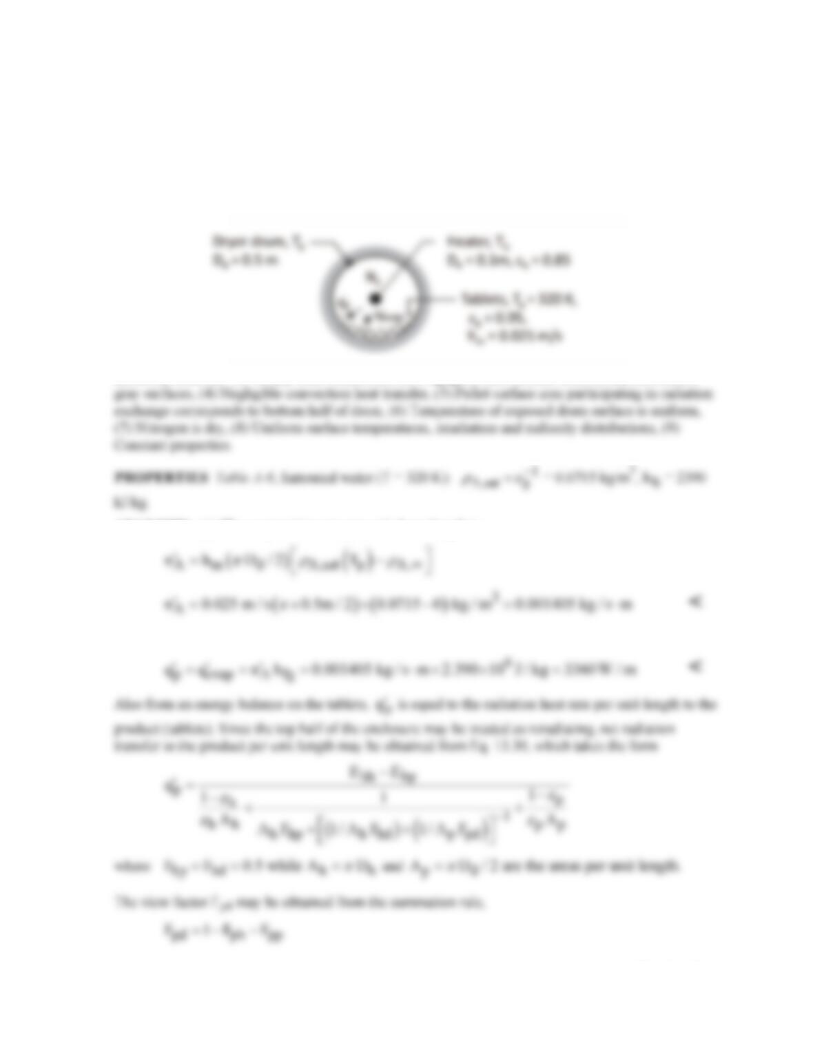
PROBLEM 13.102
KNOWN: Diameters of infrared cylindrical dryer drum and heater. Heater emissivity. Temperature
and emissivity of tablets covering half of inner drum surface. Convection mass transfer coefficient
associated with flow of nitrogen over the tablets.
FIND: (a) Evaporation rate per unit length of drum, (b) Heater temperature to drive evaporation from
tablets (c) Temperature of inner drum surface not covered by tablets.
SCHEMATIC:
ASSUMPTIONS: (1) Steady-state conditions, (2) Negligible heat transfer from drum, (3) Diffuse-
ANALYSIS: (a) The evaporation rate per unit drum length is
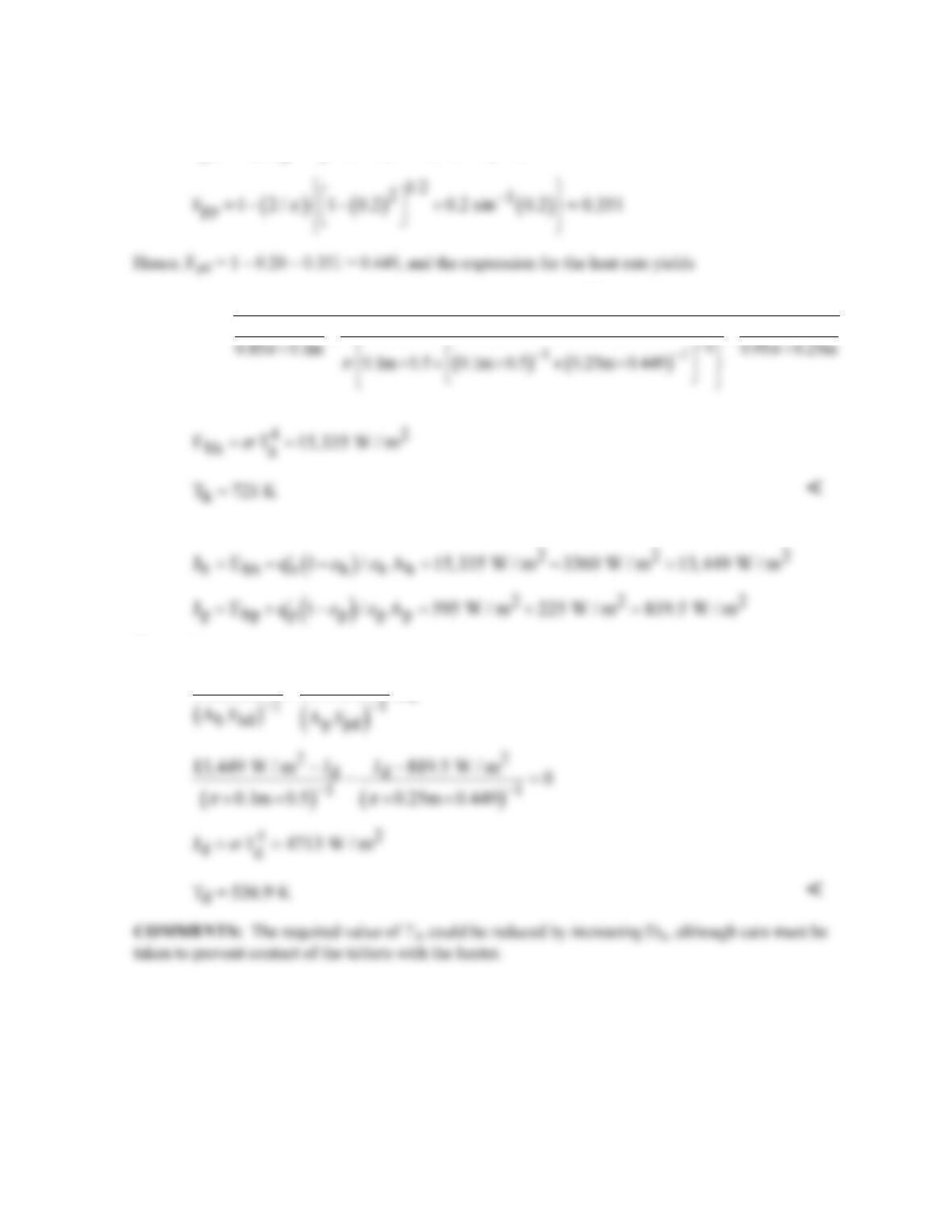
(b) From an energy balance on the surface of the tablets,
Continued …
PROBLEM 13.102 (Cont.)
where
( )
( )
ph h hp p h d
F A F / A D 0.5 / D / 2 0.20
pp
==×=
and
( )
4
bh
E 320 K
8109 W / m 0.15 1 0.05
σ
−
=
++
(c) Applying Eq. 13.19 to surfaces h and p,
Hence, from
dp
hd
JJ
JJ 0
−
−−=