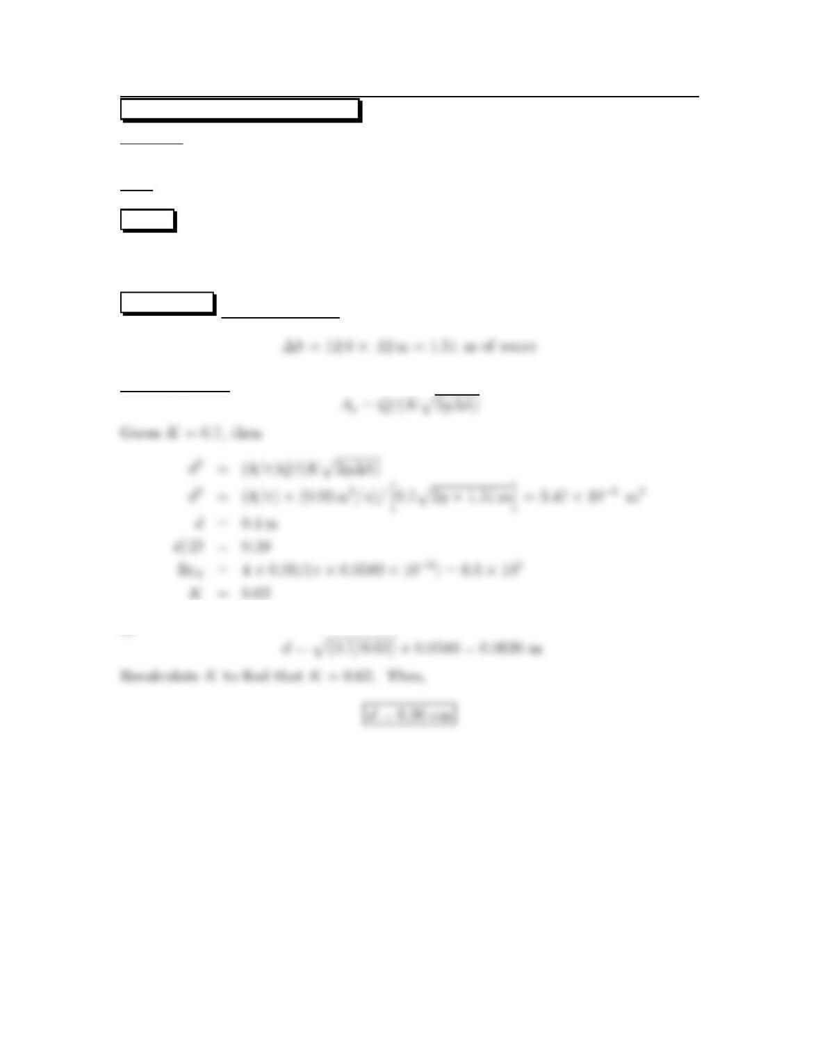
13.34: PROBLEM DEFINITION
Situation:Waterflows (Q=0.03 m3/s) through an orifice. Pipe diameter, D=15
cm. Manometer deflection is 12 cm-Hg.
Find:Orifice size: d
PLAN Calculate ∆h. Then guess K and apply the orifice equation. Check the
guessed value of Kby calculating a value of Reynolds number and then comparing
the calculated value with the guessed value.
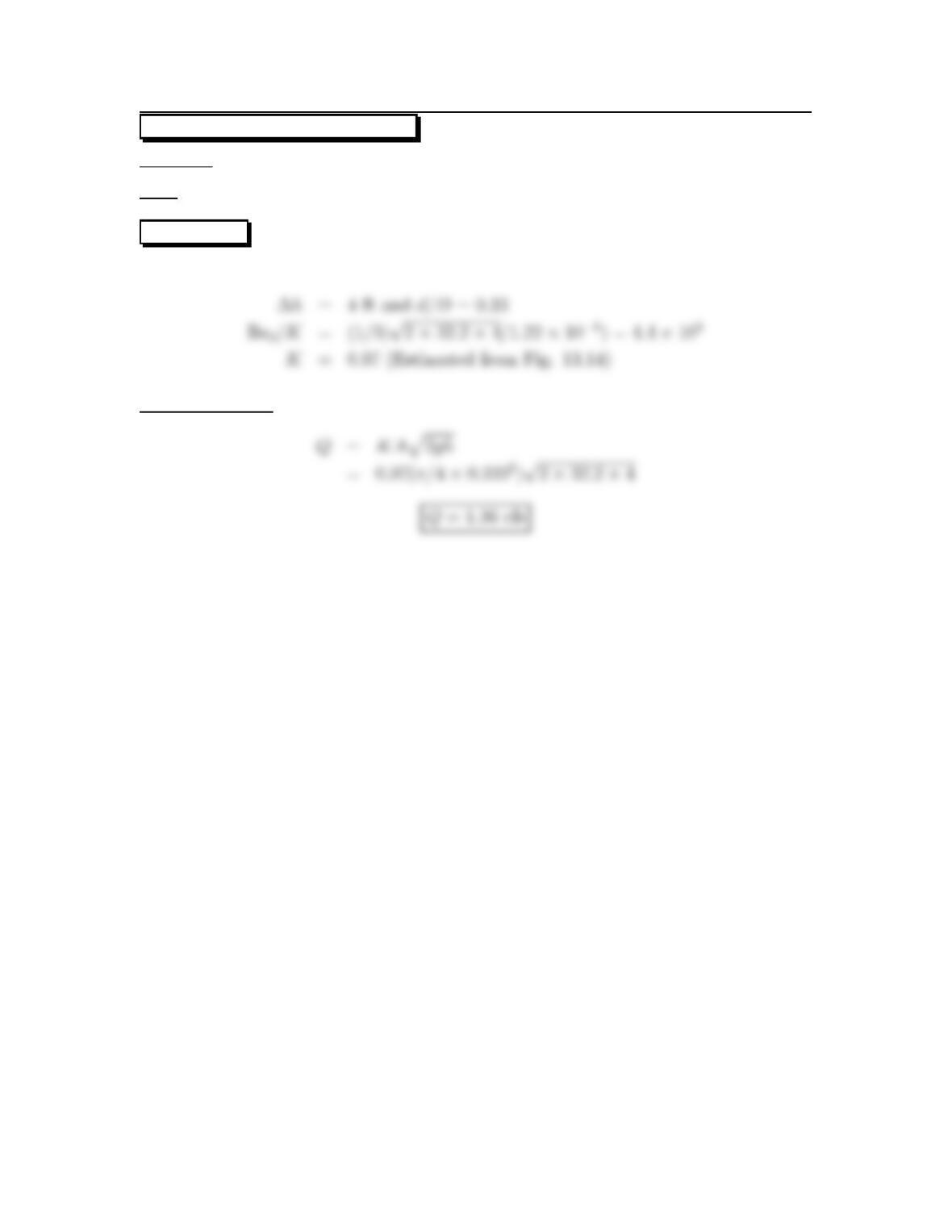
SOLUTION Piezometric head
Orifice equation
so
41
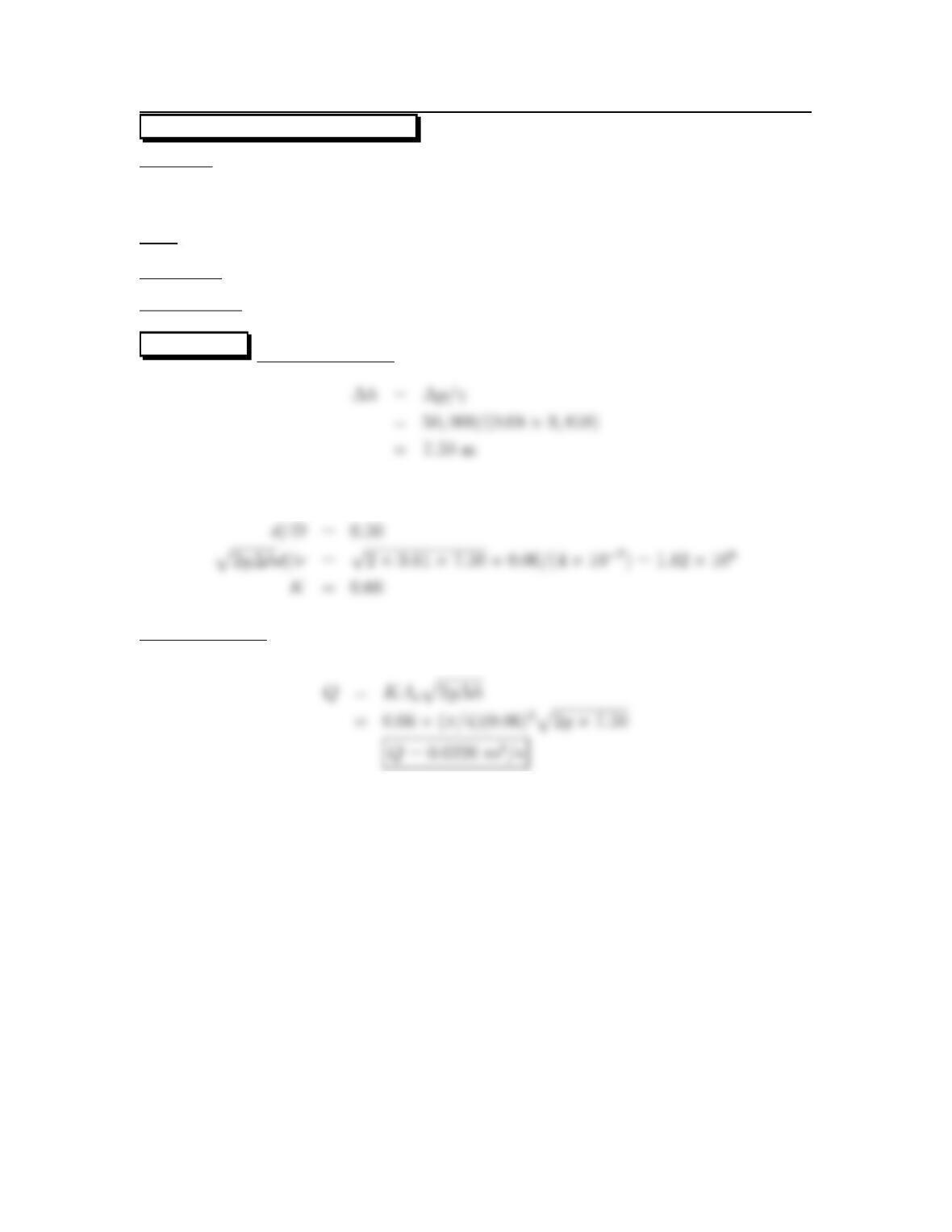
13.35: PROBLEM DEFINITION
Situation: Gasoline (S=0.68)flows through an orifice (d=6cm) in a pipe (D=12
cm).
∆p=50kPa.
Find:Discharge:Q
Properties:ν=4×10⁻⁷m2/s (Fig. A-3)
Assumptions:T=20
◦C.
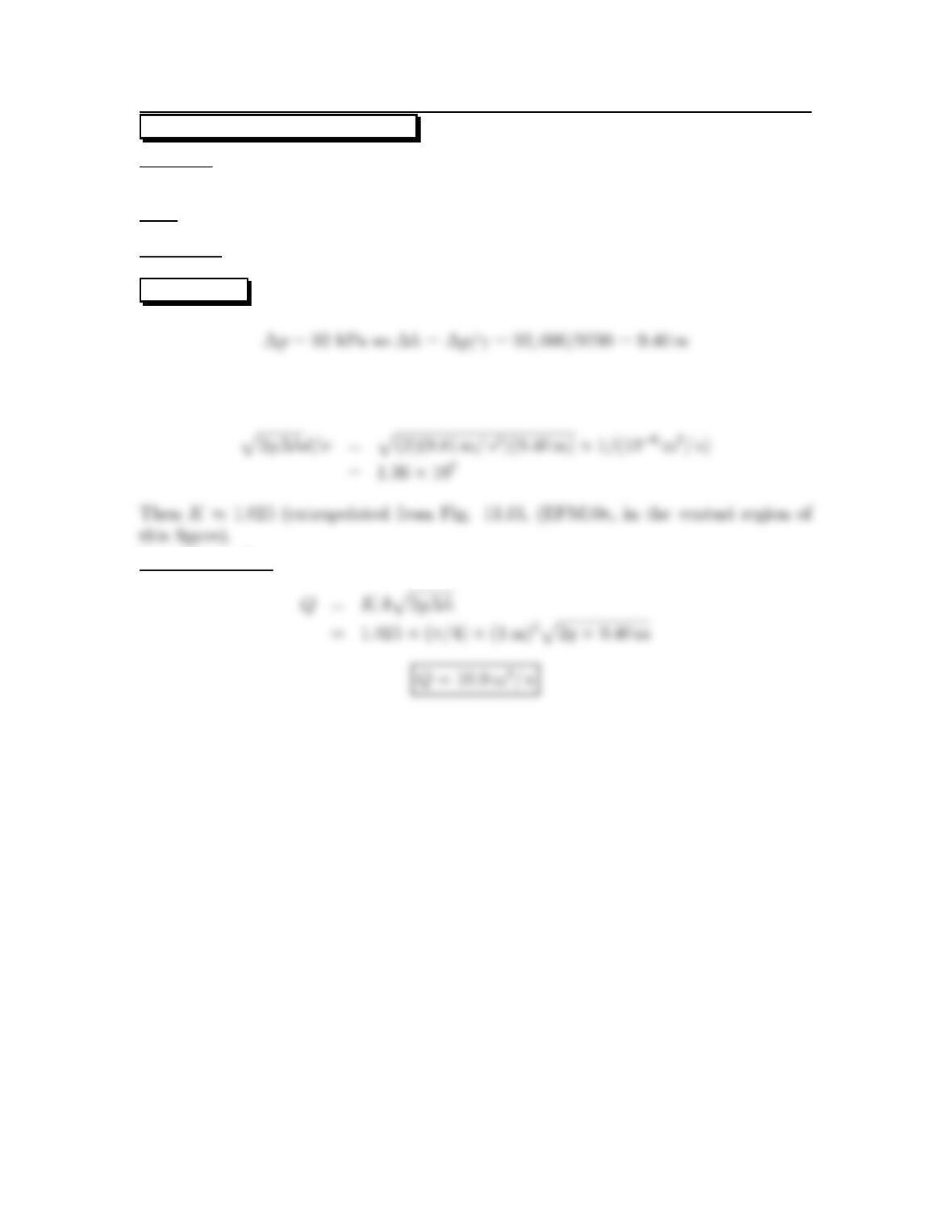
SOLUTION Piezometric head
Find K using Fig. 13.15 (EFM10e) for the region of the figure that refers to orifices
Orifice equation
42
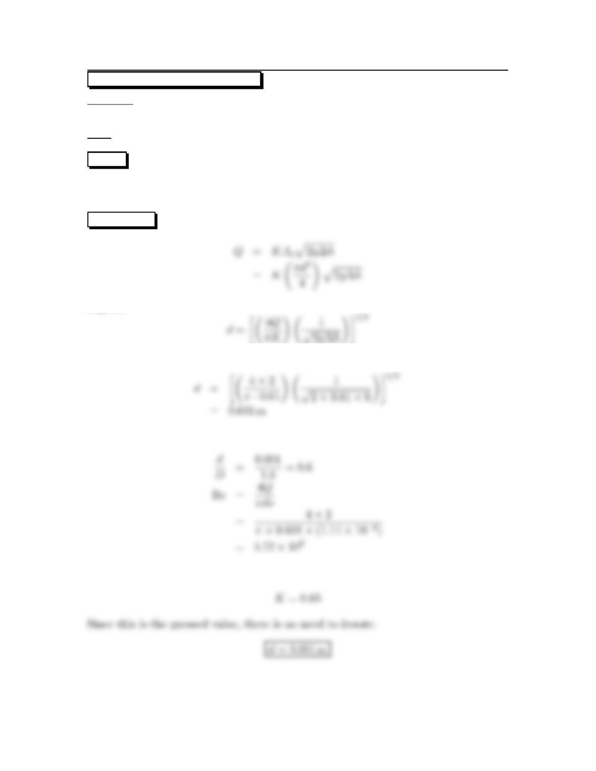
13.36: PROBLEM DEFINITION
Situation:Waterflows (Q=2m3/s) through an orifice in a pipe (D=1m). ∆h=6
m-H2O.
Find:Orifice size: d
PLAN Guess a value of K.Applytheorifice equation to solve for orifice diameter.
Then calculate Reynolds number and d/D in order to find a new value of K.Iterate
until the value of Kdoes not change.
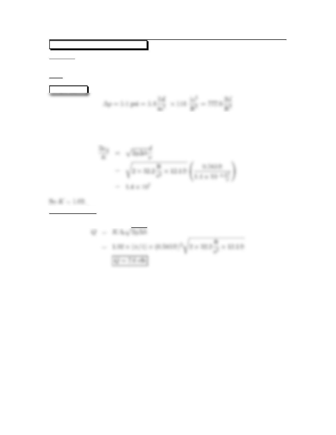
SOLUTION Orifice equation
Algebra
Guess K≈0.65
Calculate values needed for Fig. 13.14
From Fig. 13.14 (EFM10e) with d/D =0.6and Re = 3.72 ×10⁶,thevalueofKis
43
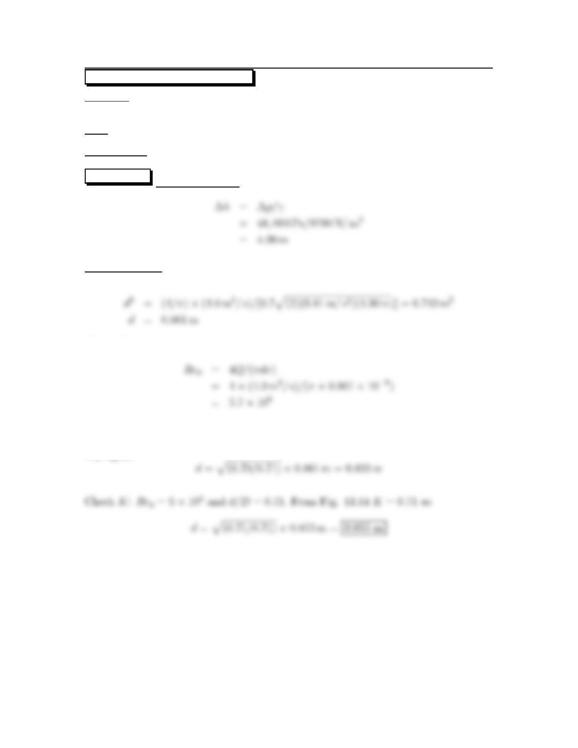
13.37: PROBLEM DEFINITION
Situation:Waterflows (Q=4m3/s) through an orifice in a pipe (D=1.2m).
∆p=48kPa.
Find:Orifice size: d
Assumptions:K=0.7; T=20
◦C.
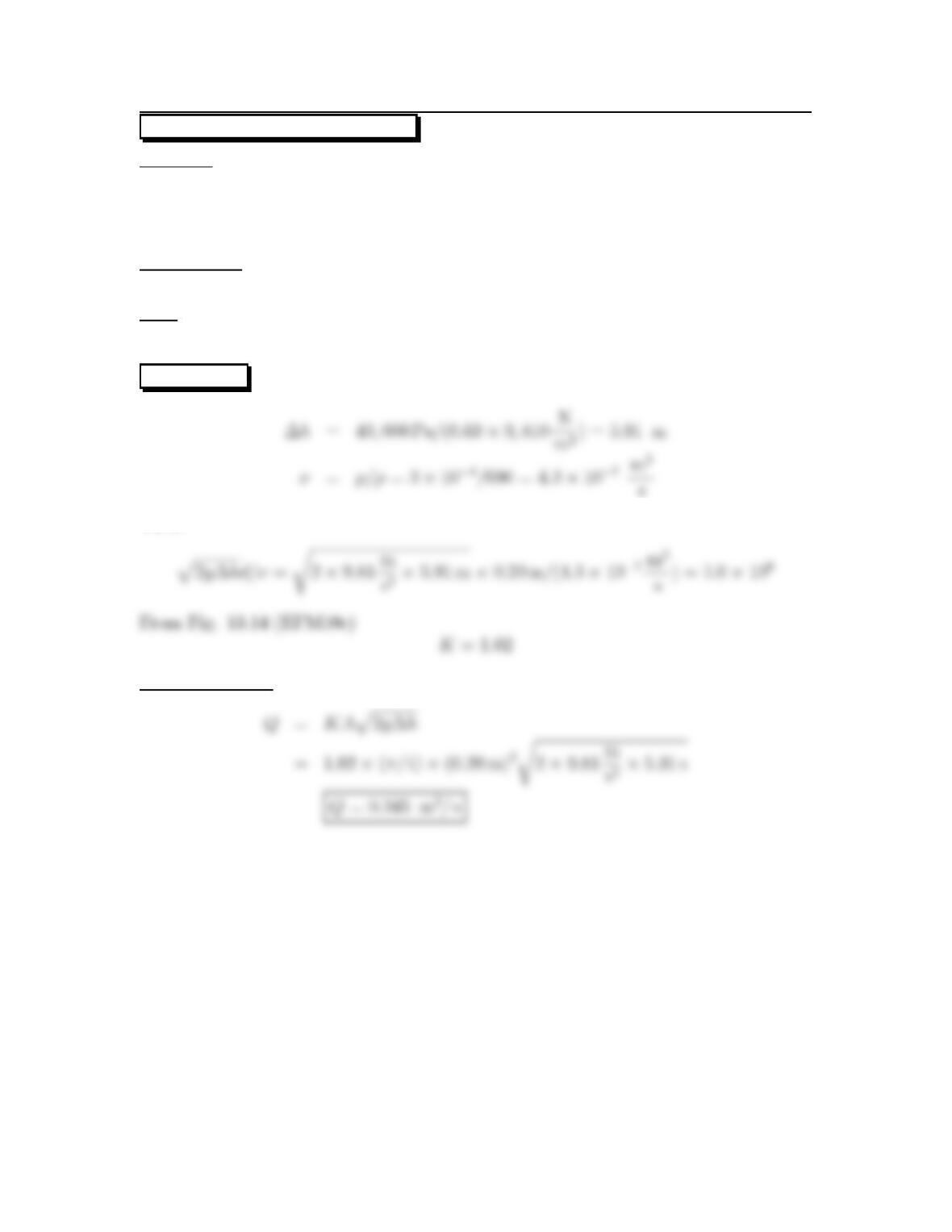
SOLUTION Piezometric head
Orifice equation
Check K:
From Fig. 13.15 (region of figure that refers to orifices) for d/D =0.861/1.2=0.72,
K=0.710
Try again:
44
13.38: PROBLEM DEFINITION
Situation:Waterflows through a hemicircular orifice as shown in the textbook.
Find:
(a) Develop a formula for discharge.
(b) Calculate Q.
PLAN Apply the flow rate equation, continuity principle, and the Bernoulli equation
to solve for Q.
SOLUTION Bernoulli equation
Continuity principle
Flow rate equation
or orifice equation
where Kis the flow coefficient. Assume K=0.65; Also A=(π/8) ×0.302=0.0353
m2.Then
45
Problem 13.39
What is the main advantage of a venturi meter versus an orifice meter? Main disad-
vantage?
Advantages:
46
13.40: PROBLEM DEFINITION
Situation:Water(20 oC, Q=0.75 m3/s) flows through a venturi meter (d=40cm)
in a pipe (D=70cm).
Find:Deflection on a mercury manometer.
SOLUTION Reynolds number
Venturi equation
Manometer equation
47
13.41: PROBLEM DEFINITION
Situation:Water(Q=0.76 m3/s) flows through a venturi meter in a horizontal pipe
(D=0.61 m). ∆p=200kPa.
Find: Venturi throat diameter.
Assumptions:T=20
◦C.
SOLUTION Guess that K=1.02,and then proceed with calculations
Venturi equation
Calculate Kand compare with the assumed value
48
13.42: PROBLEM DEFINITION
Situation: A venturi meter is described in the problem statement.
Find:Rateofflow: Q
SOLUTION Find K
Venturi equation
49

13.43: PROBLEM DEFINITION
Situation: A venturi meter is described in the problem statement.
Find: Range that the venturi meter would read: ∆p
50
13.44: PROBLEM DEFINITION
Situation:Waterflows through a horizontal venturi meter. ∆p=92kPa,
d=1m, D=2m.
Find:Discharge:Q
Properties:ν=10
−6m2/s.
SOLUTION
Find Redto compute K.
Venturi equation
51

13.45: PROBLEM DEFINITION
Situation: A poorly designed venturi meter is described in the problem statement.
Find: Correction factor: K
SOLUTION Because of the streamline curvature (concave toward wall) near the
52
13.46: PROBLEM DEFINITION
Situation:Water(50 ◦F)flows through a vertical venturi meter. ∆p=5.4psi, d=7
in., D=12in., ν=1.4×10⁻⁵ft2/s.
Find:Discharge:Q
SOLUTION
Thus
∆h=777.6/62.4=12.1ft
Find K
Venturi equation
53
13.47: PROBLEM DEFINITION
Situation:
Gasoline (S=0.69)flows through a venturi meter. A differential pressure gage
indicates ∆p=40kPa.
d=20cm, D=40cm, μ=3×10⁻⁴N·s/m2.
Assumptions:
Neglect height of transducer, h. Extraneous information.
Find:
Discharge: Q
SOLUTION
Then
Venturi equation
54
13.48: PROBLEM DEFINITION
Situation: Water passes through a flow nozzle. ∆p=8kPa. d=2cm, d/D =0.5,
ν=10
−6m2/s,ρ=1000kg/m3.
Find:Discharge:Q
PLAN FindK,andthenapplytheorifice equation.
SOLUTION Find K
From Fig. 13.14 (EFM10e) with d/D =0.5; K=0.99.
Venturi equation
55
13.49: PROBLEM DEFINITION
Situation:Waterflows through the annular venturi that is shown in the textbook.
Find:Discharge
Assumptions:Cd=0.98
SOLUTION
Estimate Kusing Eq. (13.6) in EFM10e
Venturi equation
56
13.50: PROBLEM DEFINITION
Situation: The problem statement describes a flow nozzle with d/D =1.3.
Find: Develop an expression for head loss.
PLAN Apply the sudden expansion head loss equation and the continuity principle.
SOLUTION
Continuity principle
Head loss (sudden expansion)
57
13.51: PROBLEM DEFINITION
Situation: A vortex meter (1 cm shedding element) is used in a 5 cm diameter duct.
For shedding on one side of the element, St =0.2and f=50Hz.
Find:Discharge:Q
PLAN Find velocity from the Strouhal number (St =nD/V ).Then, find the
discharge using the flow rate equation.
SOLUTION
Flow rate equation
58
13.52: PROBLEM DEFINITION
Situation: A rotameter is described in the problem statement.
Find: Describe how the reading on the rotameter would be corrected for nonstandard
conditions.
SOLUTION
Equilibrium (drag force balances weight):
Solve for velocity
V=p2gm/(ρACD)
Since all terms are constant except density
Introduce flow rate
59
13.53: PROBLEM DEFINITION
Situation:
A rotameter is calibrated for gas with ρstandard =1.2kg/m3,but is used for ρ=
1.0kg/m3.
The rotameter indicates Q=5L/s.
Find:Actualgasflow rate (Q)in liters per second.
PLAN Apply equilibrium, drag force, and the flow rate equation.
SOLUTION
The deflection of the rotameter is a function of the drag on the rotating element.
Equilibrium of the drag force with the weight of the float gives
Use the above equation to derive a ratio of standard to nonstandard conditions gives
60