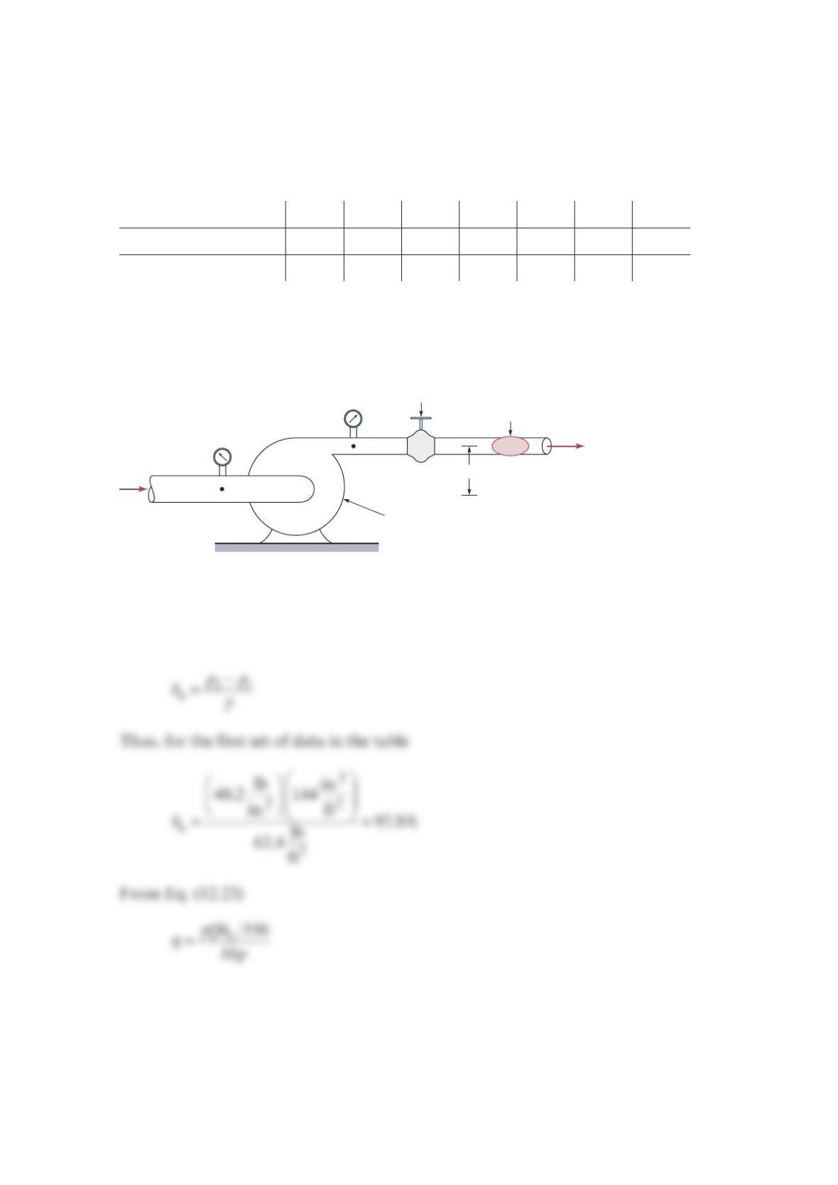
Problem 12.13
The performance characteristics of a certain centrifugal pump having a 9-in.-diameter
impeller and operating at
1
750 rpm are determined using an experimental setup similar to
that as shown in the figure below. The following data were obtained during a series of tests
in which −=
21
0zz , =
21
VV
, and the fluid was water.
Q (gpm) 20 40 60 80 100 120 140
p2 − p1 (psi) 40.2 40.1 38.1 36.2 33.5 30.1 25.8
Power input (hp) 1.58 2.27 2.67 2.95 3.19 3.49 4.00
Based on these data, show or plot how the actual head rise, a,
h
g and the pump efficiency,
η
,
vary with the flowrate. What is the design flowrate for this pump?
Solution 12.13
From Eq. (12.19), with =
12
zz
and =
12
VV
z
2
–
z
1
(1)
(2)
Flowrate meter
Valve for varying
system resistance
Behind pump (out of sight):
Drive shaft and motor with
speed and power measurement
Q
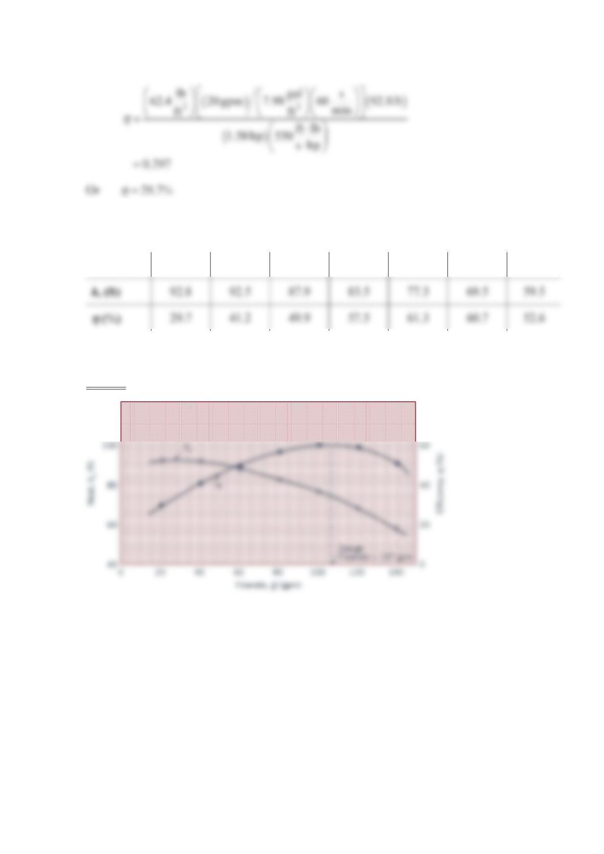
And for the first set of data in the table
Remaining values for a
h and
η
can be calculated in a similar manner, and all values are
tabulated in the table below.
Q (grm) 20 40 60 80 100 120 140
A plot of the data is shown below. The design flowrate occurs at peak efficiency and is
1
07gp
m
.
120
80
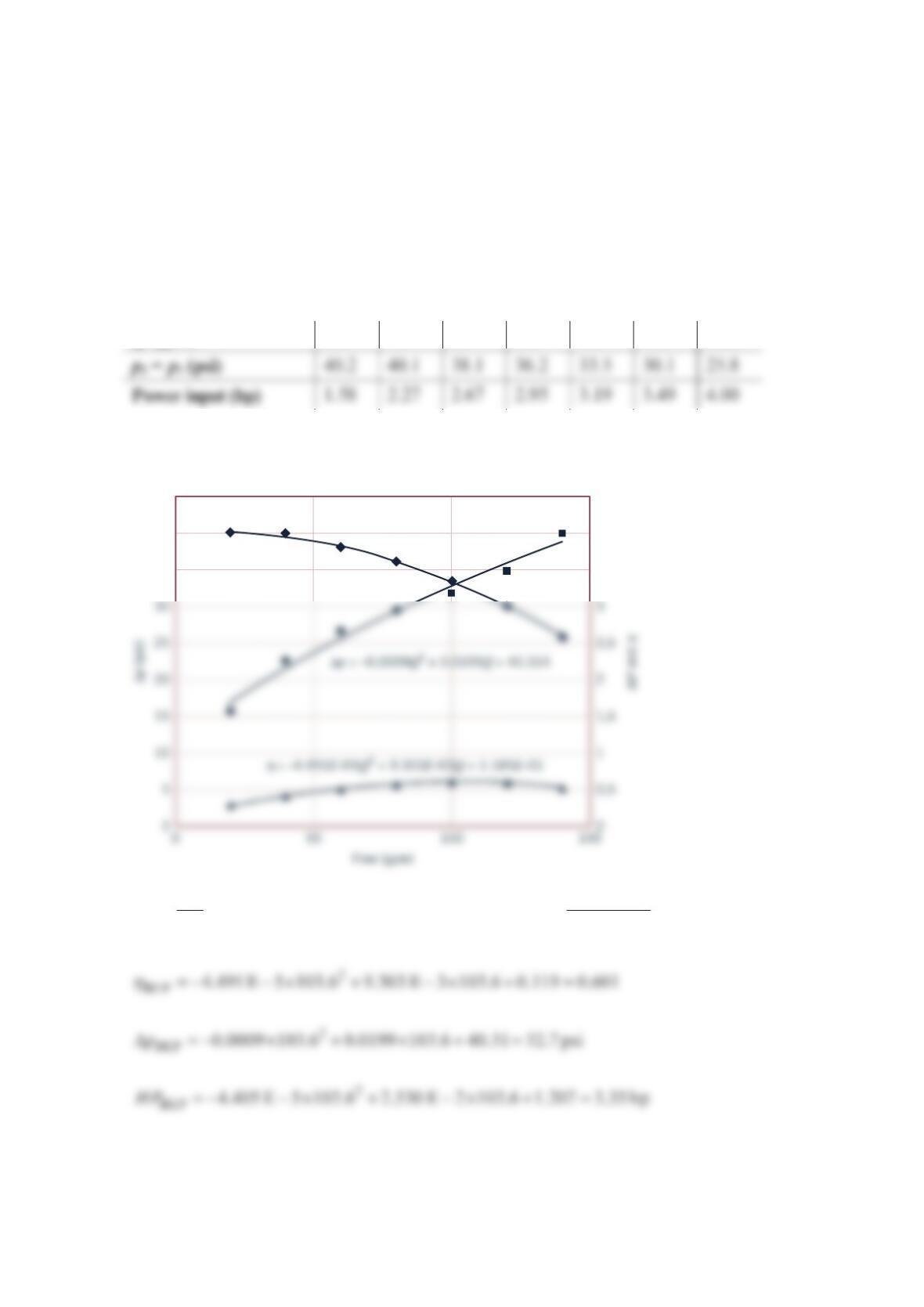
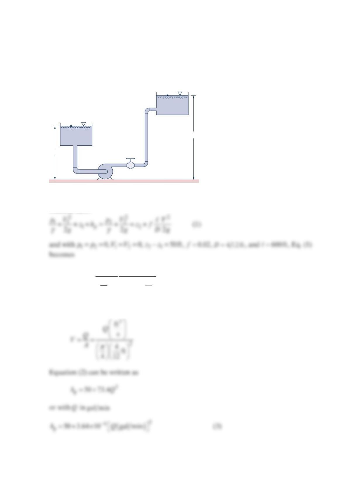
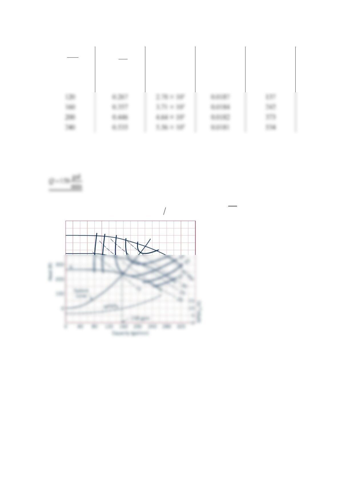
Problem 12.14
Determine algebraic equations for the pump head rise, power, and efficiency as functions of
flowrate based on the data from Problem 12.13. Analytically determine the Best Efficiency
Point and the BEP flow, head rise, and power. How do these values compare with those
from Problem 12.13?
Solution 12.14
The data from Problem 12.13 are
Q (gpm) 20 40 60 80 100 120 140
The figure shows plots and curve fits made with Microsoft® Excel®
η
−
=×− − + −= ==
−
BEP
9.303 E 5
BEP: 2 ( 4.491E 5) 9.303 E 5 0 103.6 gpm
8.982 E 3
dQ
dQ
HP = –4.405E–05Q
2
+ 2.530E–02Q + 1.207E + 00
35
40
45
3,5
4
4,5
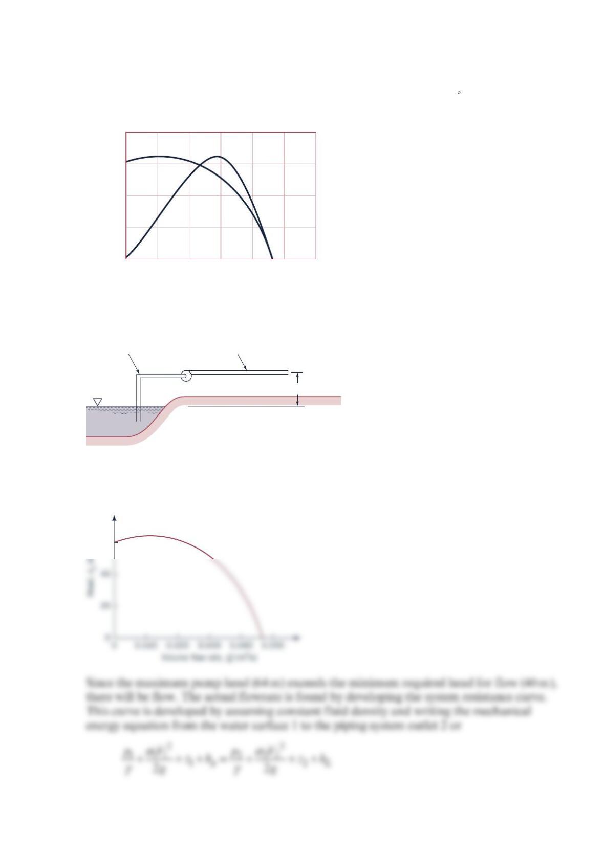
Problem 12.15
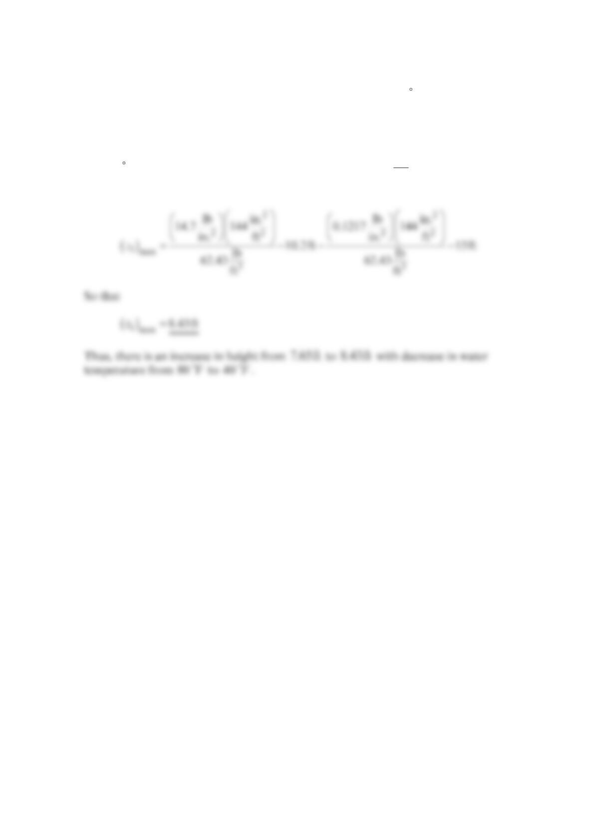
In Example 12.3, how will the maximum height, 1
z, that the pump can be located above the
water surface change if the water temperature is decreased to 40 F ?
Solution 12.15
For 40 F water, vapor pressure is 0.1217 psia and
γ
=3
lb
62.43 ft . Thus, with this change
Eq. (1) in Example 12.3 becomes:
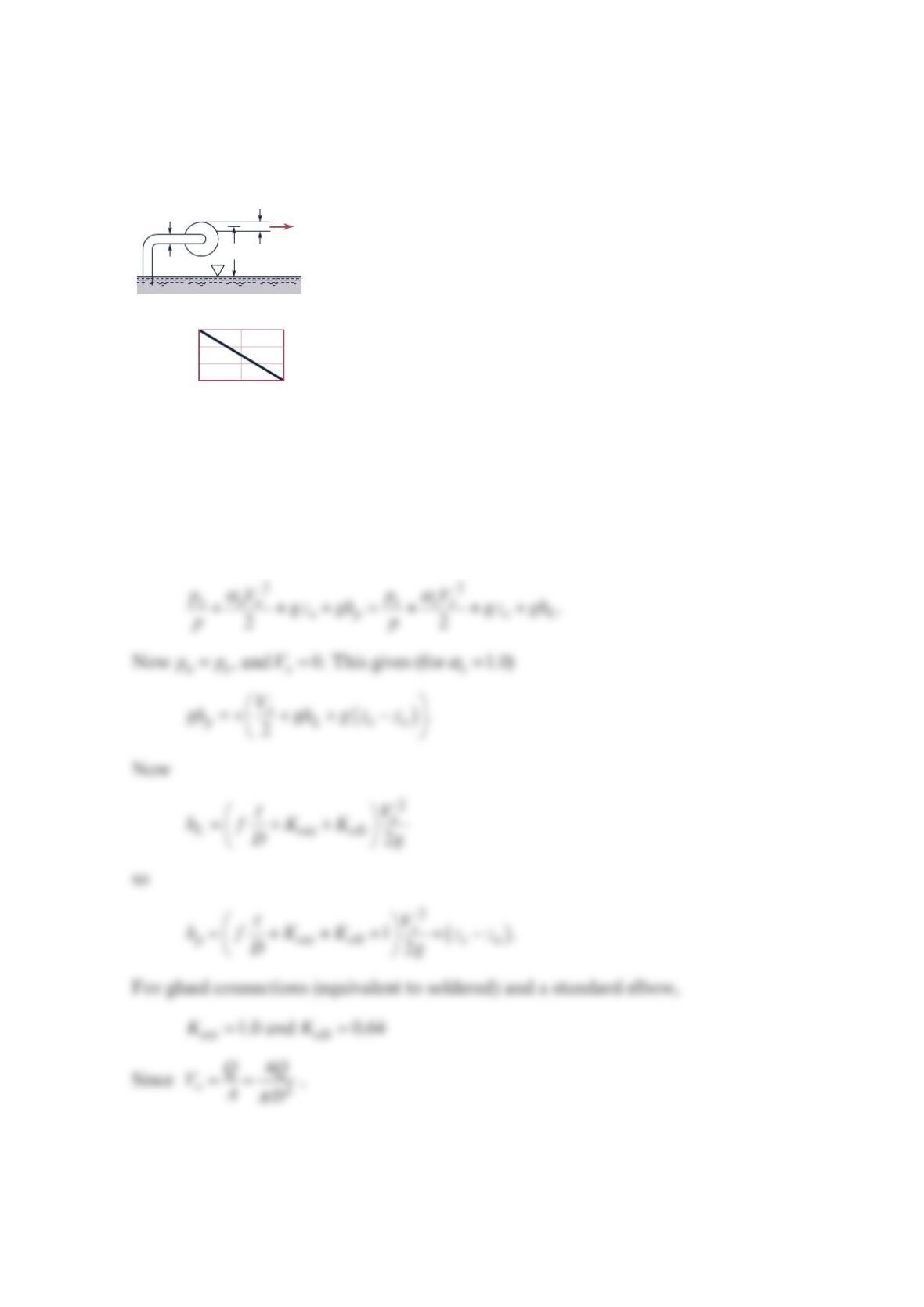
Problem 12.16
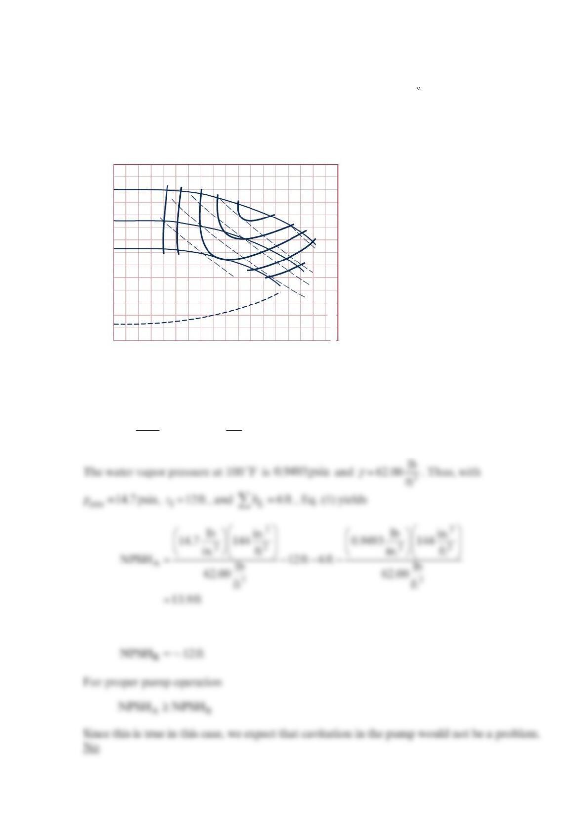
A centrifugal pump with a 7-in.-diameter impeller has the performance characteristics as
shown in the figure below. The pump is used to pump water at 100 F , and the pump inlet
is located 12 ft above the open water surface. When the flowrate is 200 gpm , the head loss
between the water surface and the pump inlet is 6 ft of water. Would you expect cavitation
in the pump to be a problem? Assume standard atmospheric pressure. Explain how you
arrived at your answer.
Solution 12.16
From Eq. (12.25)
γγ
=−− −
A1
N
PSH atm V
L
p
p
zh (1)
From the pump performance characteristics at
2
00 gpm
0 40 80 120 160 200 240 280 320
NPSH
R
NPSH
R
, ft
8 in. dia
7
6
50%
55
60
63
65
50
55
60
63
65
40 bhp
30
25
20
15
Capacity, gal/min
Head, ft
0
100
200
300
400
500
15
10
5
0
Problem 12.17
Water at 40 C is pumped from an open tank through
2
00 m of 50-mm-diameter smooth
horizontal pipe as shown in the figure below and discharges into the atmosphere with a
velocity of
3
m/s. Minor losses are negligible. (a) If the efficiency of the pump is
7
0%, how
much power is being supplied to the pump? (b) What is the A
N
PSH at the pump inlet?
Neglect losses in the short section of pipe connecting the pump to the tank. Assume
standard atmospheric pressure.
Solution 12.17
(a)
0
And from the Moody Chart for smooth pipe =0.0152
f
. Thus, from Eq. (2)
Diameter = 50 mm
Length = 200 m
Pump
3 m
(1)
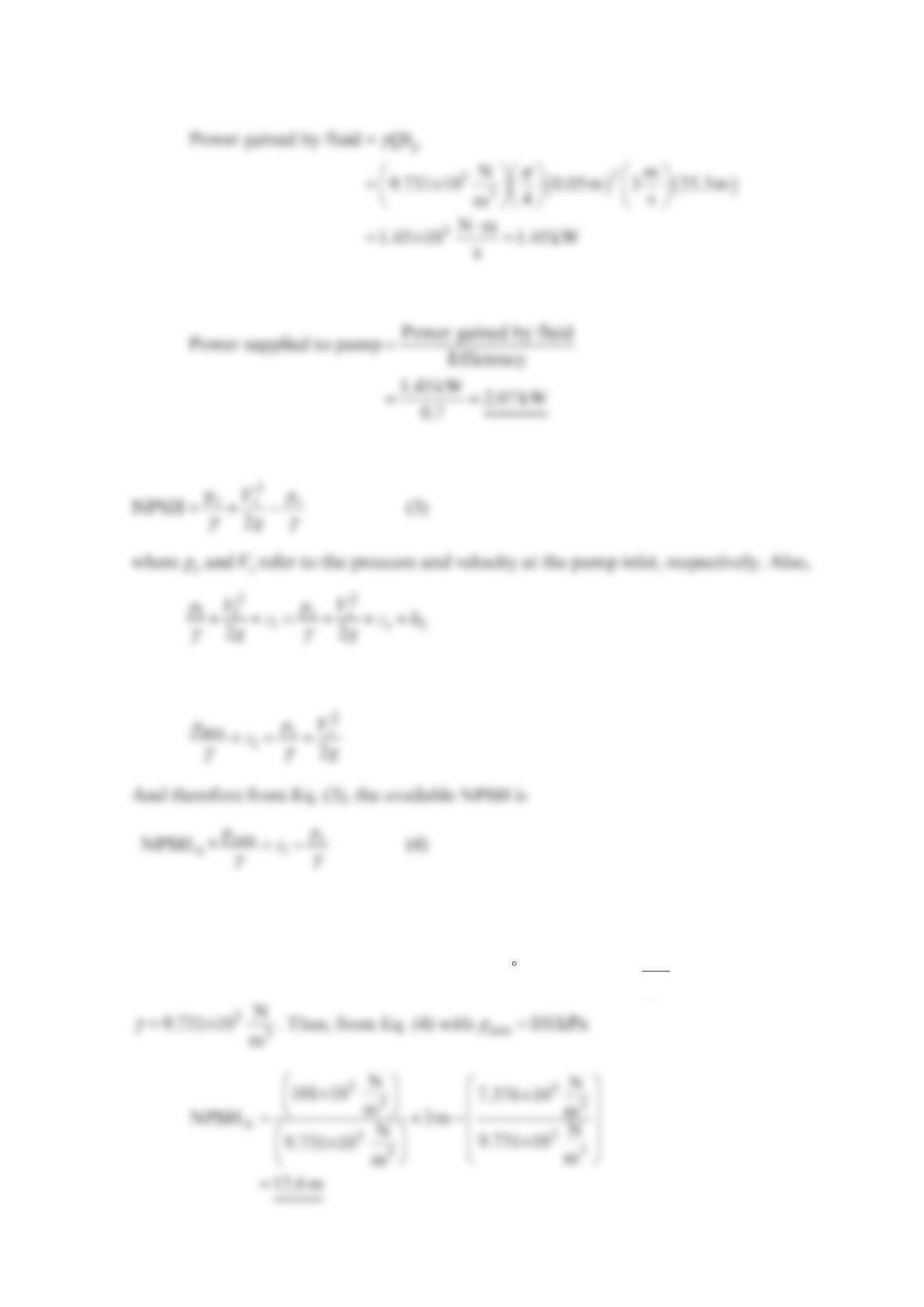
Hence,
And
From Eq. (12.24)
So that with =
1atm
p
p, =
10V, =
0
s
z, and =0
L
h
p
Note that this result corresponds to Eq. (12.25) with 1
z positive (since pump is below
reservoir) and =
0
L
h.
From Table B.2, the water vapor pressure at 40 C is ×3
2
N
7.376 10 (abs)
m and
Problem 12.18
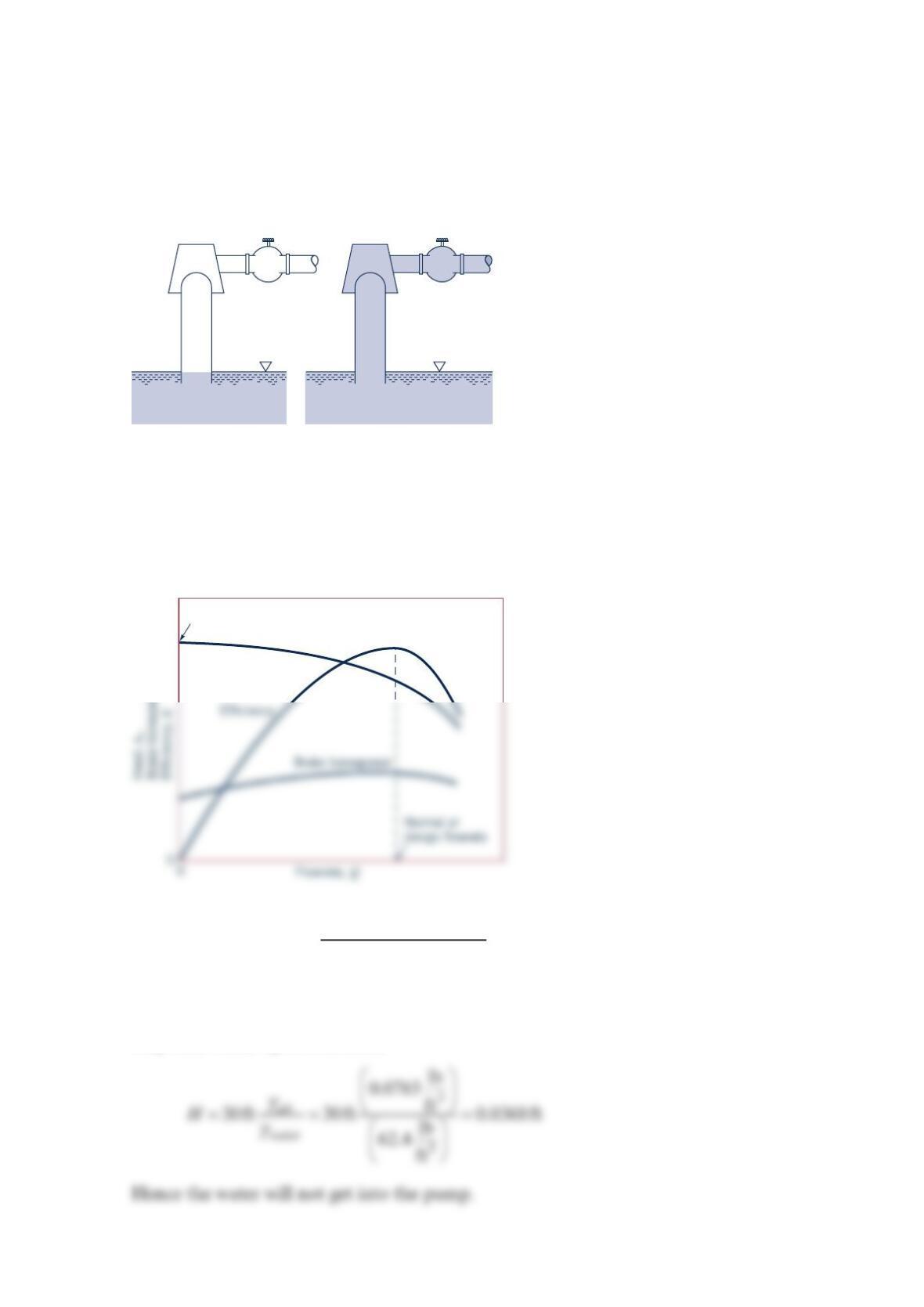
The centrifugal pump shown in the figure below is not self-priming. That is, if the water is
drained from the pump and pipe as shown in the figure below (a), the pump will not draw
the water into the pump and start pumping when the pump is turned on. However, if the
pump is primed [i.e., filled with water as in the figure below (b)], the pump does start
pumping water when turned on. Explain this behavior.
Solution 12.18
The head-flowrate characteristics for a typical centrifugal pump are shown in the figure
below.
The maximum head that the pump can add occurs when ≈0Q (i.e., at start up for example).
This head is in terms of the fluid in the pump. Neglecting losses and the velocity head (and
cavitation effects) the pump can lift the fluid a height
H
equal to the head added by the
pump. However, if the fluid in the pump is air (i.e., not primed) the head added is in terms
of ft or
m
of air. For example, if =
a30 fth the pump could raise water that high if it is
primed (filled with water). If the pump is not primed (filled with air) then the pump can
only raise water up to a distance
Pump Pump
(a)(b)
Shutoff head
Head
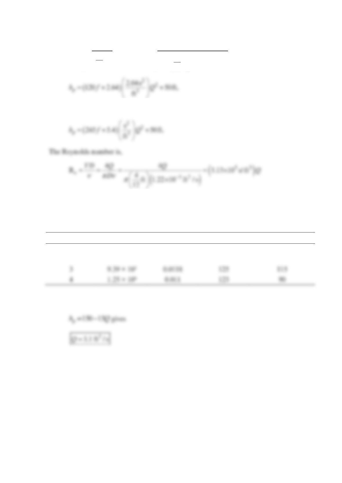
Problem 12.19
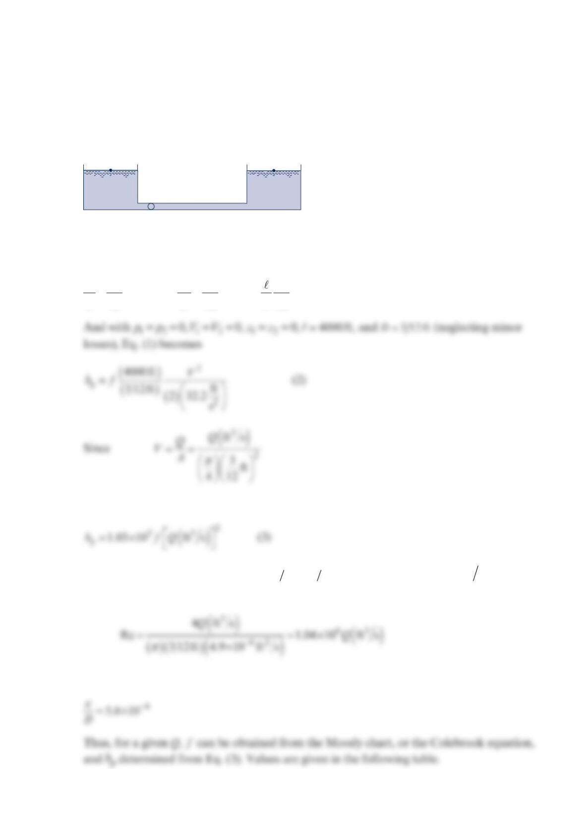
A centrifugal pump having a head-capacity relationship given by the equation
−
=− ×
42
a180 6.10 10hQ
, with a
h in feet when
Q
is in gp
m
, is to be used with a system similar
to that shown in the figure below. For −=
21
50 ftzz , what is the expected flowrate if the
total length of constant-diameter pipe is 600ft and the fluid is water? Assume the pipe
diameter to be 4in.
and the friction factor to be equal to 0.02. Neglect all minor losses.
Solution 12.19
()
()
=+
2
p
2
600 ft
50 ft 0.02 4ft
ft 2 32.2
12 s
V
h (2)
Since
Q
(1)
Pump
(2)
z
1
z
2

The pump head-capacity relationship is
Problem 12.20
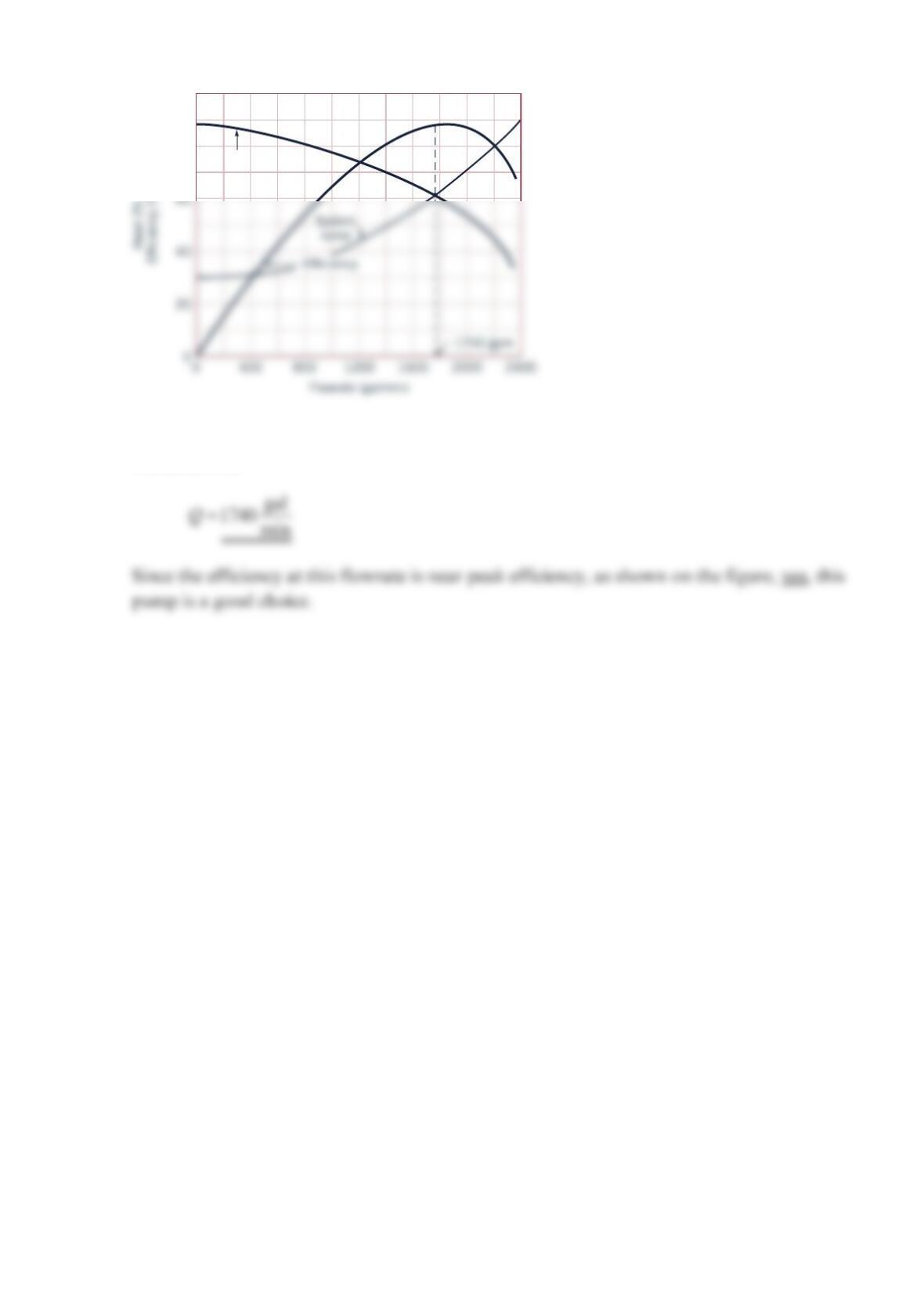
A centrifugal pump having a 6-in.– diameter impeller and the characteristics shown in Fig.
12.12 is to be used to pump gasoline through 4000 ft of commercial steel 3-in.- diameter
pipe. The pipe connects two reservoirs having open surfaces at the same elevation.
Determine the flowrate. Do you think this pump is a good choice? Explain.
Solution 12.20
γγ
+++=+++
22
2
11 2 2
12
222
p
pV p V V
zh z f
ggDg
(1)
Equation (2) can be written as
The friction factor depends on
π
==Re 4VD v Q Dv and with −
=×
62
4.9 10 ft sv for
gasoline
For commercial steel 3-in.- diameter pipe (from the Moody Chart)
(1) (2)
Pump
gal
min
Q
3
ft
s
Q
Refhp (ft)
40 0.0891 9.27 × 1040.0208 17.0
80 0.178 1.85 × 1050.0193 63.0
These data
()
vs.
p
hQ
are plotted on Fig. 12.12 (reproduced below), and the flowrate at the
intersection of the system curve and the pump curve is
Since at this flowrate, the pump operates near peak efficiency, yes, this type of pump would
appear to be a good choice if the 158gal min flowrate is at or near the desired flowrate.
8 in. dia
7
50%
55
60
63
65
65
400
500
Problem 12.21
A centrifugal pump having the characteristics shown in Example 12.4 is used to pump
water between two large open tanks through 100 ft of
8
-in.- diameter pipe. The pipeline
contains four regular flanged °
9
0 elbows, a check valve, and a fully open globe valve. Other
minor losses are negligible. Assume the friction factor =0.02
f
for the
1
00-ft section of pipe.
If the static head (difference in height of fluid surfaces in the two tanks) is 30ft, what is the
expected flowrate? Do you think this pump is a good choice? Explain.
Solution 12.21
Application of the energy equation between the two free surfaces, points (1) and (2), gives
The head loss term can be expressed as
With the minor loss coefficients obtained from Table 8.3. Also,
The intersection of the system curve [Eq. (3)] with the pump curve, as shown on the figure,
indicated that
Head
100
80
Problem 12.22
Both the suction and discharge piping for the pump shown in the figure below consist of
4-in. I.D. 40–ft-long plastic pipe. Find the volume flowrate of 60 °F water through the
pump. The connections are glued (equivalent to soldered connections).
Solution 12.22
Assume constant water density and steady flow. Apply the mechanical energy equation
from the water surface (o) to the pipe exit (e).
50 ft
Volume flow rate
Q
(ft3/s)
Pump head
hp
(ft)
150
0
0510
50
100
d
1 = 4 in.
d
2 = 4 in.
Q
()
()
2
4
22
40 ft 16
1.0 0.64 1 50 ft
44
ft 2 ft 32.2 ft / s
12 12
p
Q
h
f
π
=+++ +
,
and
The plastic pipe is considered smooth pipe. We must plot p
h versus
Q
. Tabulating several
values gives
Q (ft3/s) Refhp (ft) hp = 150 − 15Q (ft)
0 0 —- 50 150
26.26 × 1050.0126 84 120
The intersection of this curve with the pump head curve,
Problem 12.23
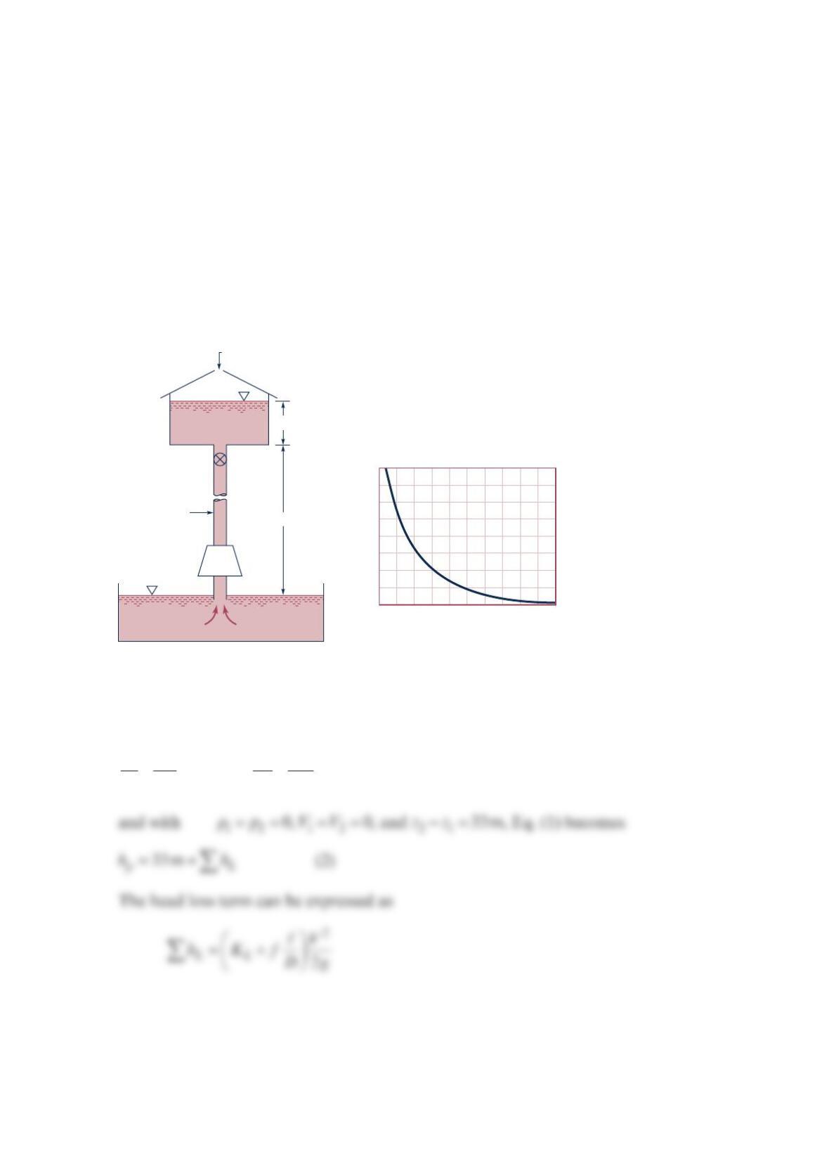
In a chemical processing plant, a liquid is pumped from an open tank, through a 0.1-m–
diameter vertical pipe, and into another open tank as shown in the figure below (a). A valve
is located in the pipe, and the minor loss coefficient for the valve as a function of the valve
setting is shown in the figure below (b). The pump head capacity relationship is given by the
equation a
h
Q
32
52.0 1.01 10=−× with ha in meters when
Q
is in 3
m
/s. Assume the friction
factor =0.02
f
for the pipe, and all minor losses, except for the valve, are negligible. The
fluid levels in the two tanks can be assumed to remain constant.
(a) Determine the flowrate with the valve wide open.
(b) Determine the required valve setting (percent open) to reduce the flowrate by
50%.
Solution 12.23
γγ
+++=+ ++
22
11 2 2
1p 2 L
22
pV p V
zh z h
gg
(1)
0
20 40 60 80 100
10
20
30
40
0
(Open)
(Closed)
% valve setting
Valve
D = 0.1 m
Open
Pump
K
L
30 m
3 m
(a)(b)
(a) With the valve open L
K
1.0≈(from figure b) so that with =0.02
f
, =30 m , and
=0.1mD, Eq. (2) can be written as
Equation (3) becomes
Since the pump equation is
Equations (5) and (6) can be equated to determine the flowrate. Thus,
(b) If the flowrate is to be cut in half so that
From Eq. (4) with L
K
unknown

Problem 12.24
Two of the pumps in the figure below are operated in series to supply water through the
piping system. Determine the flowrate through the piping system for 10 C water and
screwed connections. Then find the total power input to the two pumps.
Solution 12.24
The head-flow characteristic curve for two pumps in series is made by adding the head for
the same flowrate. This gives the pump characteristic shown below.
0 10 20 30 40 50 60
30
20
10
0
60
80
40
20
60 m of 0.10-m
inside diameter,
commercial steel
pipe, one swing
check valve, four
90° standard
elbows
240 m of 0.10-m
inside diameter, commercial
steel pipe, four gate valves,
one fully open globe valve,
twelve 90° standard elbows,
four tees with flow through
lines
Volume flow rate,
Q
(l
3
/s)
Head,
hp
(m)
h
p
Efficiency (%)
η
η
40 m
60