Problem 12.60
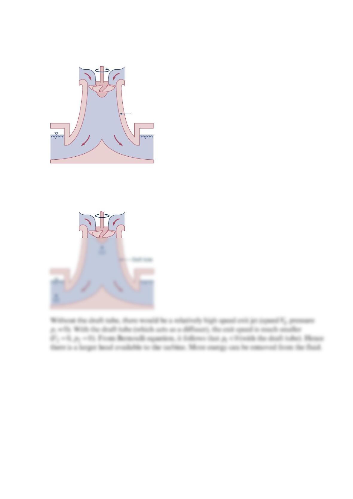
Draft tubes as shown in the figure below are often installed at the exit of Kaplan and
Francis turbines. Explain why such draft tubes are advantageous.
Solution 12.60
Draft tube
Problem 12.61
Turbines are to be designed to develop
3
0,00
0
horsepower while operating under a head of
7
0 ft and an angular velocity of 60rpm. What type of turbine is best suited for this
purpose? Estimate the flowrate needed.
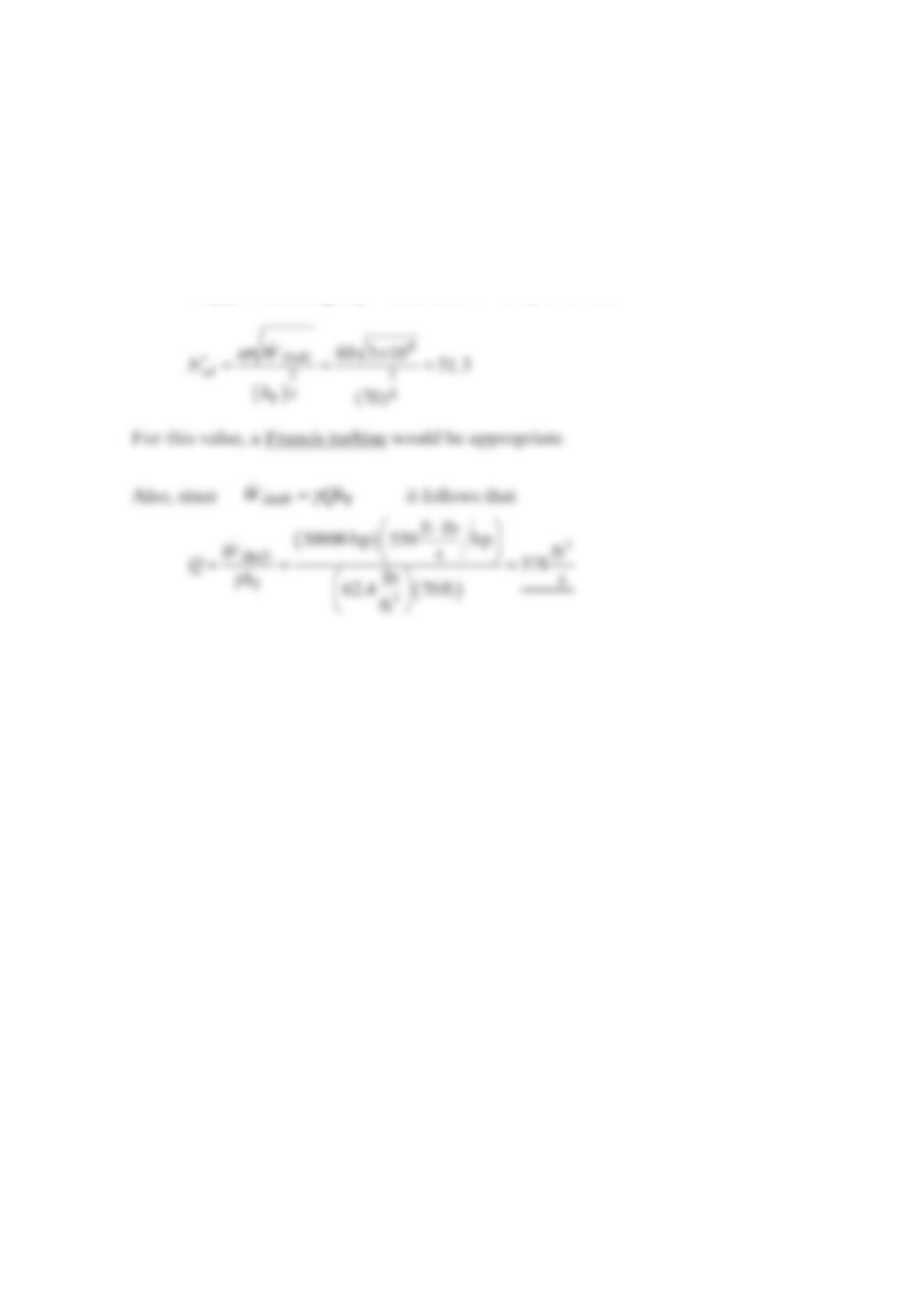
Solution 12.61
=
.
shaft 30,000 hp;W =
T70 ft;h and
ω
=60rpm so that
Problem 12.62
Water at 400 psi is available to operate a turbine at 1750 rpm. What type of turbine would
you suggest to use if the turbine should have an output of approximately 200 hp ?
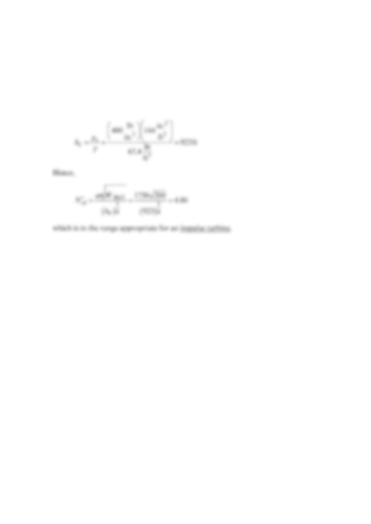
Solution 12.62
With =
o400 psi,p the maximum turbine head would be
Problem 12.63
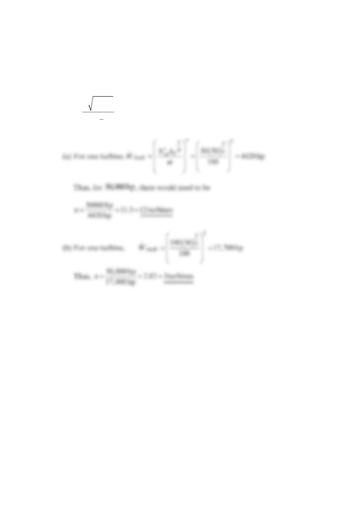
It is desired to produce 50,000 hp with a head of 50 ft and an angular velocity of 100rpm.
How many turbines would be needed if the specific speed is to be (a) 50, (b) 100?
Solution 12.63
sd
T
W
N
h
.
shaft
5
4
ω
′= where
ω
=100 rpm, T
h
50 ft=
Problem 12.64
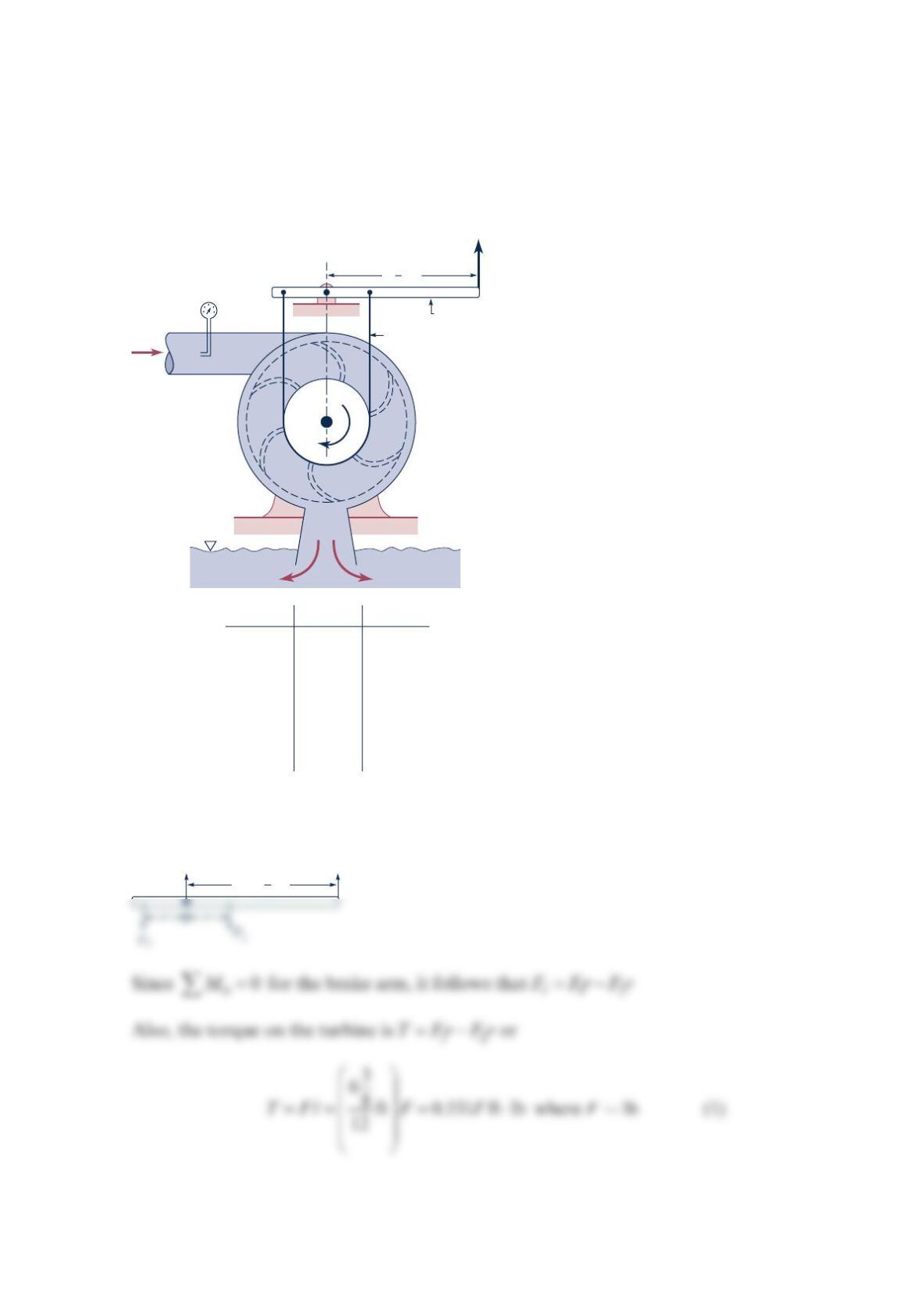
Test data for the small Francis turbine shown in the figure below is given in the following
table. The test was run at a constant 32.8-ft head just upstream of the turbine. The Prony
brake on the turbine output shaft was adjusted to give various angular velocities, and the
force on the brake arm, ,
F
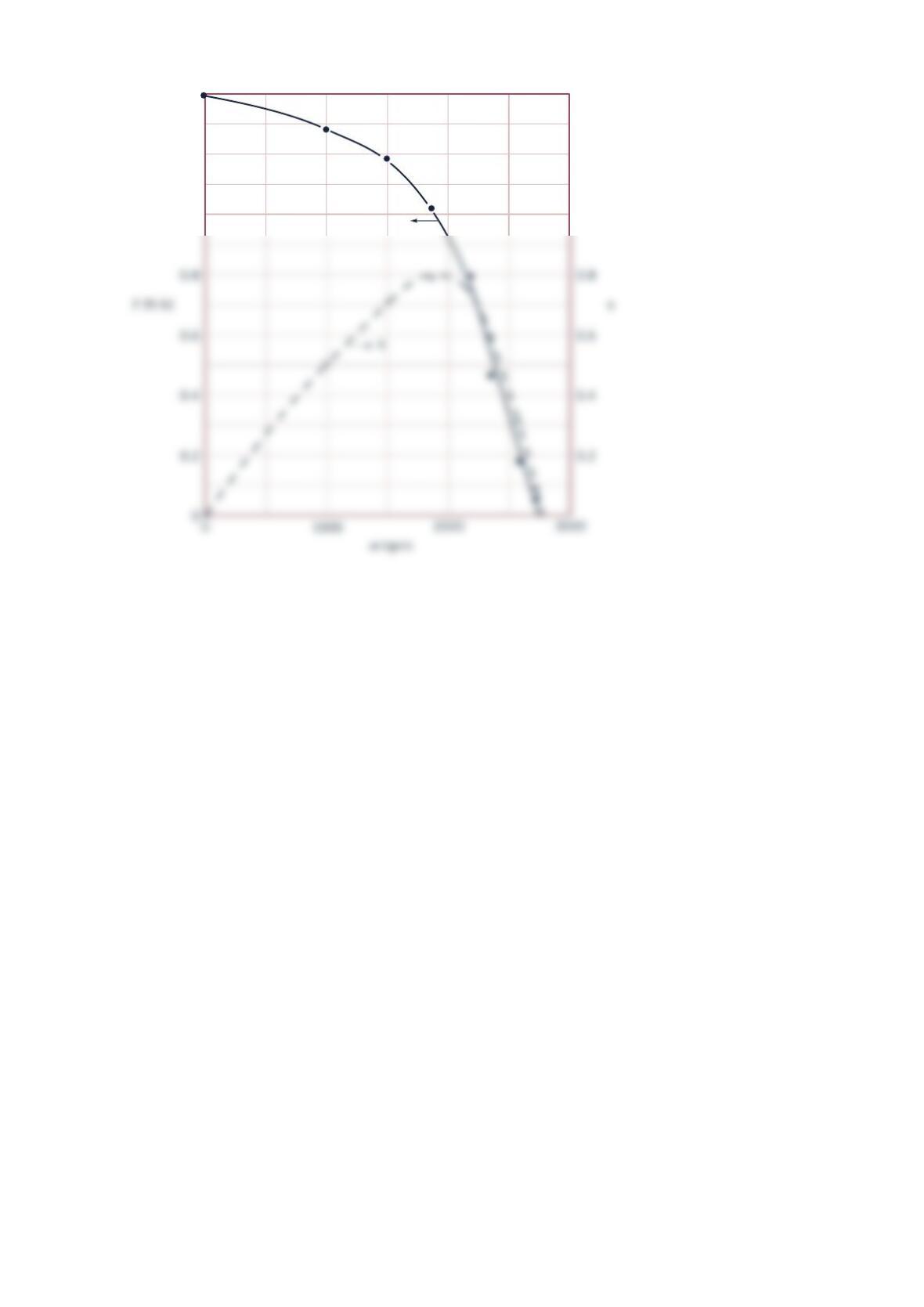
was recorded. Use the given data to plot curves of torque as a
function of angular velocity and turbine efficiency as a function of angular velocity.
Solution 12.64
F
Q
Brake arm
Brake cord
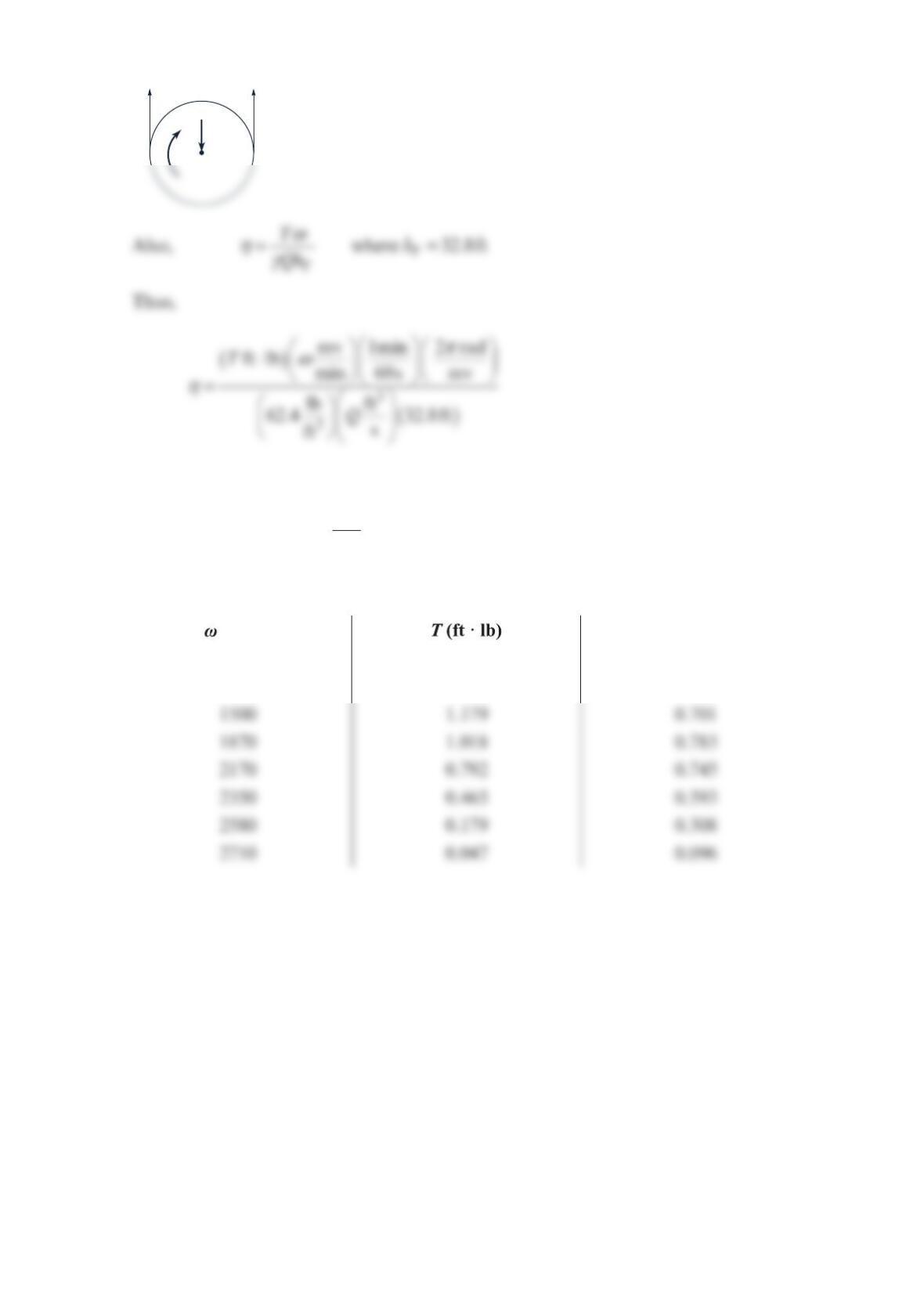
(rpm) Q (ft
3
/s) F (lb)
0
1000
1500
1870
2170
2350
2580
2710
0.129
0.129
0.129
0.124
0.118
0.0942
0.0766
0.068
2.63
2.40
2.22
1.91
1.49
0.876
0.337
0.089
ω
ω
6 in.
3
8
F
Oy
6 in.
3
8
ℓ
=
or
ω
η
−
=×
5
5.116 10 T
Q where ft lb,T⋅ rpm,
ω
cfsQ (2)
Values of
T
and
η
are given in the table below and plotted in the graphs shown.
(rpm) n
01.397 0
1000 1.275 0.506
TR
F1
F2
T
1.0
1.0
1.2
1.4
Problem 12.66
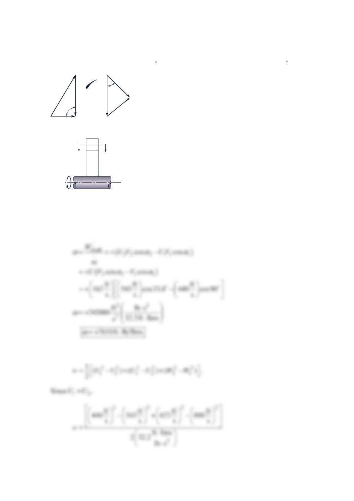
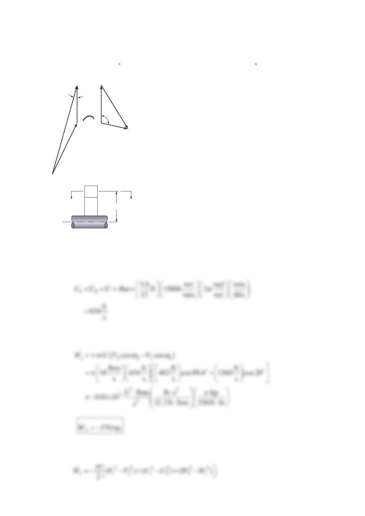
An axial flow compressor stage shown in the figure below has the inlet and outlet velocity
diagrams shown. Calculate the work per unit mass. Quantities are ===
12 762 ft/s,UU U
=
1440 ft/s,V =
1880 ft/s,W
α
=
190 , =
2545ft/s,V =
2622 ft/s,W and
α
=
253.8 .
Solution 12.66
The work per unit mass is
Alternatively,
W2
W1U2
U2
V2
V1
2
α
1
α
Blade
Section
AA
AA

Problem 12.67
The axial flow gas turbine stage shown in the figure below has a mean blade radius of
=5.0 in.,R a rotational speed of 15,000 rpm, a mass flowrate of 10.0lbm/s, =
1972 ft/s,W
=
11560 ft/s,V
α
=
120 , =
2874 ft/s,W =
2483ft/s,V and
α
=
299.4 . Find the power
transmitted from the gas to the turbine blade.
Solution 12.67
The blade midheight velocity is
The Euler Turbomachine equation gives
Alternatively,
W
2
W
1
UU
V
2
V
1
2
α
1
α
Blade
Section
AA
AA
R
= 5 in.

Since ==
12
UU U
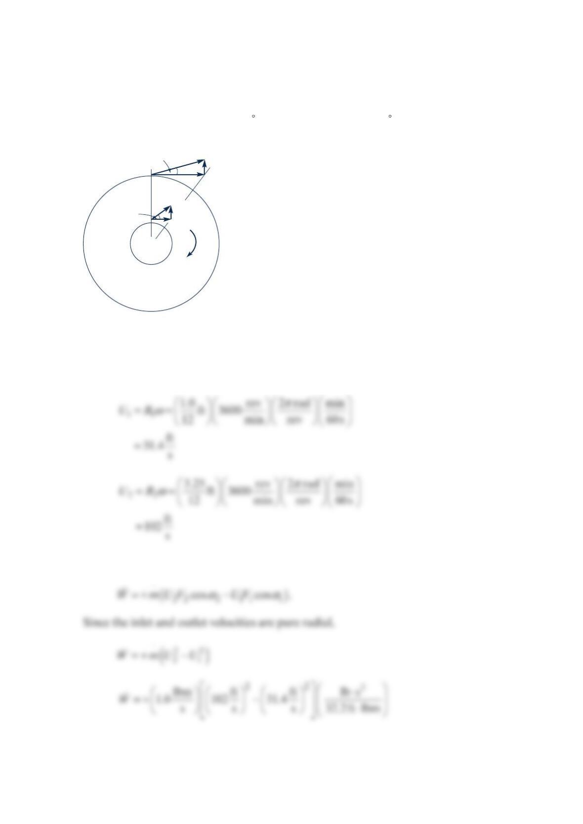
Problem 12.68
A centrifugal air compressor has a rotor inner diameter of =
12.0 in.,D a rotor outer
diameter of =
26.5 in.,D a rotor depth of 10 in., and a rotor rotational speed of 3600rpm.
The fluid relative velocities (W) are purely radial. The compressor delivers an air mass
flowrate of 1.0 lbm/s with =
170 F,T =
114.7 psia,p =
2240 F,T and =
233.1psia.p Find
the power transferred by the rotor to the air and the inlet relative velocity 1.
W
Solution 12.68
The rotor speeds 1
U and 2
U are
The power transferred by the compressor to the fluid
+
ω
α
W
1
W
2
U
1
U
2
V
1
1
α
2
V
2
The inlet relative velocity 1
W is
Assuming the air is an ideal gas,
Comment Because the power and thus the pressure rise is small, this machine would be
more aptly called a fan or a blower.
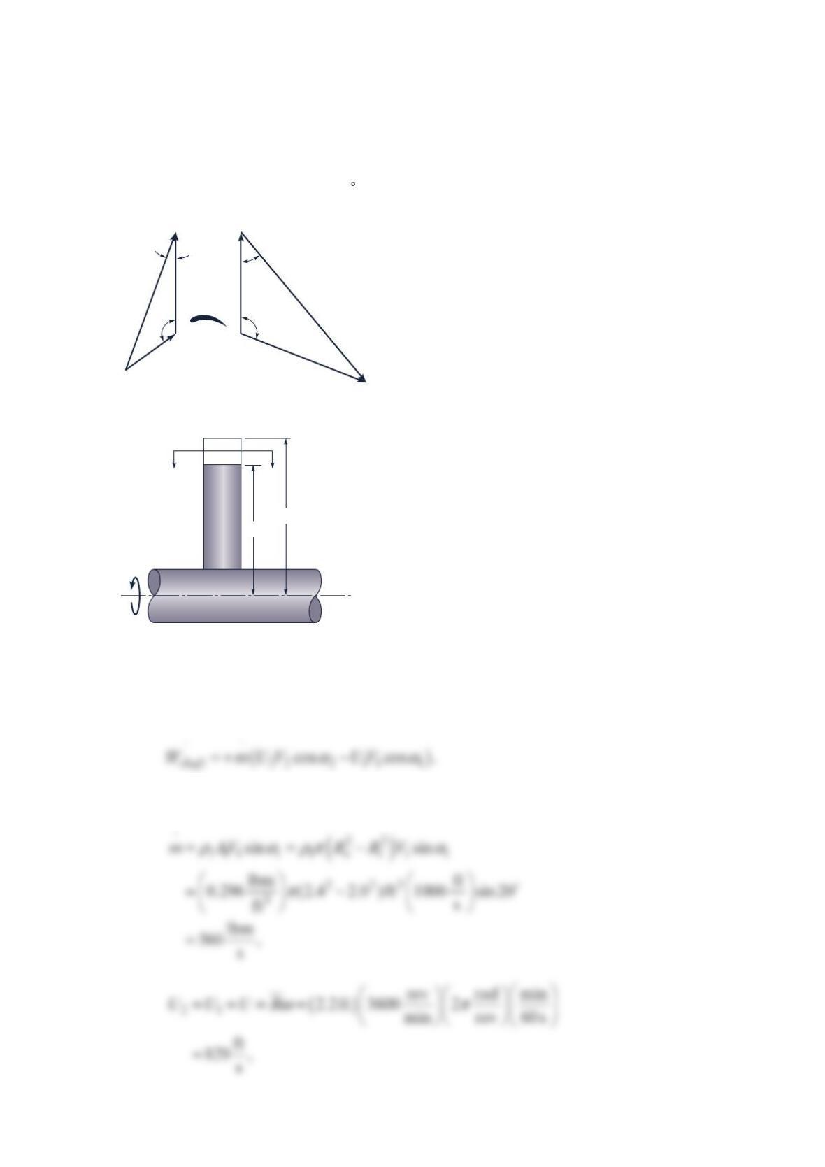
Problem 12.69
The axial flow steam turbine rotor shown in the figure below has a blade outer radius
=
o2.40 ft,R a blade inner radius =
i2.00 ft,R a steam inlet pressure =
1 200 psia,p a steam
inlet density
ρ
=3
10.296 lbm/ft , and an inlet absolute velocity =
1 1000 ft/sV making an
angle of 70° with the axial direction. The steam outlet pressure =
250 psiap and outlet
density is 3
0.1014 lbm/ft .
β
=
240 . The rotor rotates at 3600 rpm. Using a blade velocity at
the blade midheight =2.2 ,(0ft)R find the power transferred from the steam to the rotor.
Solution 12.69
The power transfer is
Now
W
1
W
2
UU
V
1
V
2
1
β
2
β
2
α
Section
AA
AA
R
o
1
α
Turbine
blade
= 20°
R
i
And 2
V is found from the continuity equation
Since
β
α
=
2222
sin sin
,
WV
α
β
===
22
2
2
ft
998
sin ft
s1553
sin s
sin 40
V
W
And the law of cosines gives
And
Then
[]
shaft
W
mU V V
2211
2
cos cos
lbm ft ft ft lb s s hp
560 829 1061 cos109.8 1000 cos 20
s s s s 32.2 ft lbm 550 ft lb
αα
⋅
=+ −
⋅⋅
=+ −
⋅⋅
Problem 12.70
The figure below shows a nozzle vane and a rotor blade for an axial flow gas turbine stage.
The blade speed is 800 ft/s. The absolute velocity leaving the stage is identical to the
absolute velocity entering the stage and both are purely in the axial direction.
(a) Draw and label the velocity diagrams. Show values for all three velocities and the
absolute and relative angles on each diagram.
(b) Calculate the work per unit mass for this stage.
Solution 12.70
NOTE: In this solution, the symbol C is used for the absolute velocity
=== =
33 tan 40 671ft s
xx
CC CU
The velocity diagrams are shown above
U
= 800 ft/s 40°
30°
30°
1
32