Problem 12.40
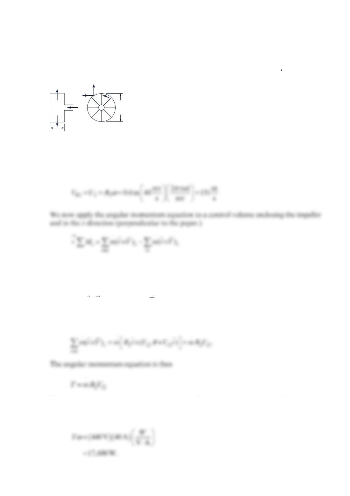
A lossless motor drives the fan shown in the figure below at 40 Hz. The power input to the
motor is 40 A at 440 V. For the geometry shown, what is the discharge flowrate of air
through the fan? Assume that the tangential component of the velocity leaving the impeller
is equal to that of the impeller at that point. The exit air temperature =
215 C.T
Solution 12.40
The tangential component of velocity 2
V is
Now
z
MTtorque driving fan ,==
z
in
mr V()0
⋅
×=
since
V
is in the z-direction,
And
The fan input power is the product of the torque
T
and fan rotational speed. Since there are
no energy losses in the motor, the motor input power equals the motor output power which
equals
ω
.T Therefore,
Vr2
V
2
Q
Vr2
0.3 m
1.2 m
ω
θ
Then
ωω
⋅
==
22
17,600 W t
TmRV
Or
Problem 12.41
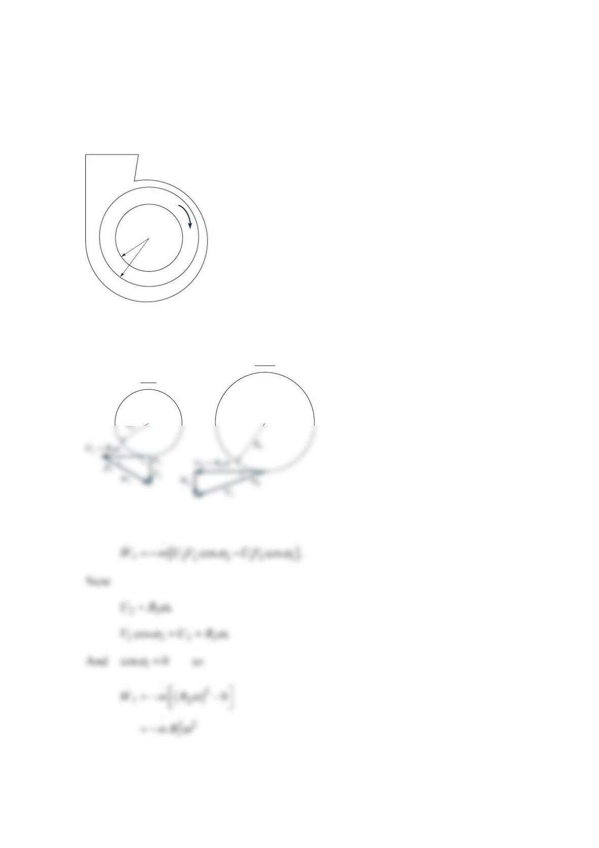
A centrifugal fan has a power input of 25kW, an inner radius of =
10.5 m,R an outer
radius of =
21.0 m,R and delivers 100kg/s of air. There are no friction losses, the air inlet
absolute velocity has no tangential component, and the outlet absolute velocity has a
tangential component equal to the blade velocity at the outer radius 2.
R
The rotor depth
(i.e., blade height) is 1.0 m. What is the required rotational speed of the rotor?
Solution 12.41
The fan power is
+
ω
R
1
R
2
inlet
outlet
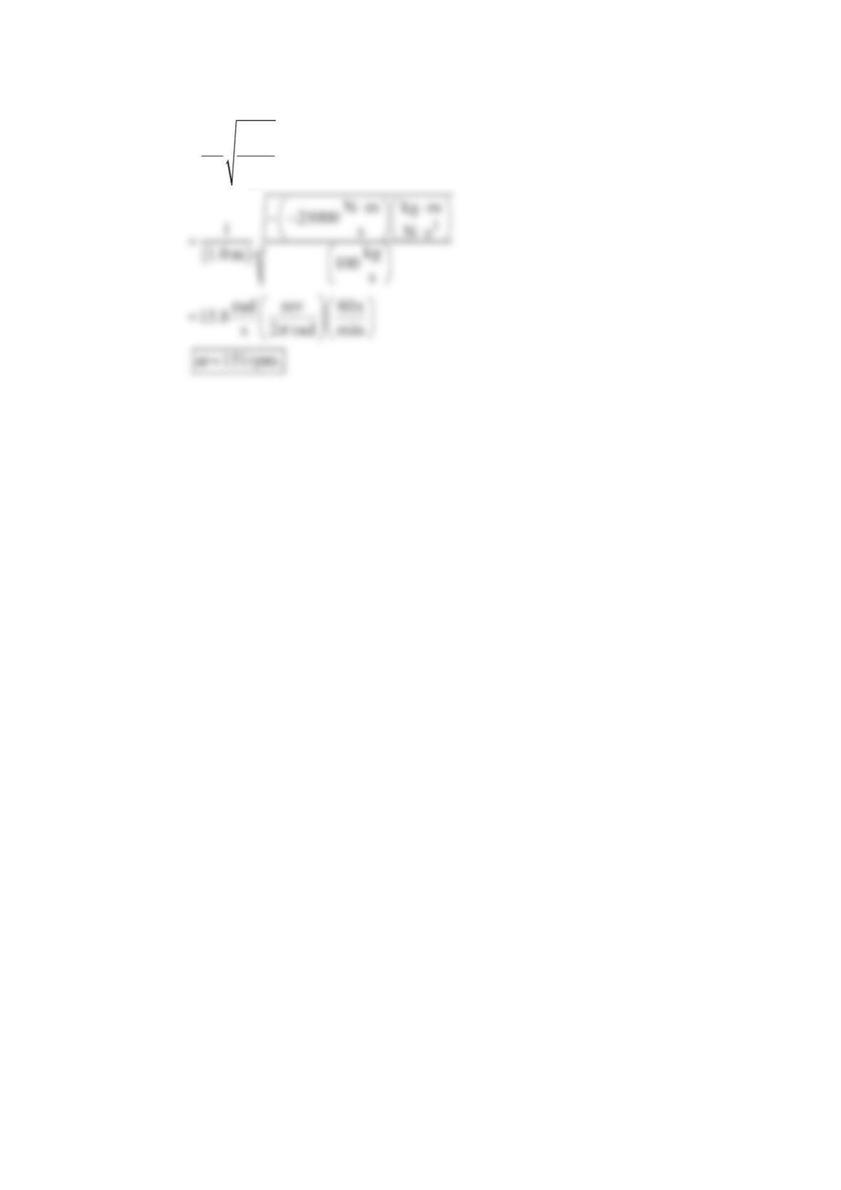
Or
ω
⋅
⋅
−
=
2
1
s
W
Rm
Problem 12.42
An axial fan operating at 1000rpm has the characteristics shown in the figure below. It
delivers 15 °C atmospheric air through a 50-cm I.D., galvanized, sheet-metal, horizontal
duct having a length of 175 m and seven °
9
0 long-radius elbows. For constant air density,
what is the flowrate if the duct discharges to the atmosphere?
Solution 12.42
Assume steady flow and uniform properties over each flow cross section. Apply the
mechanical energy equation from the duct inlet 1 to the duct outlet 4 to get
Now
0 50 100 150 200
0
5
10
15
20
Air flow rate (m
3
/min)
Static head (cm H
2
O)
34
where
h
is the static head in cm.H2O so
Equations (1) and (2) give
Or
h
h
The Moody Chart and Minor Loss Tables give
Assuming complete turbulence, the Moody chart gives =0.0145.
f
Fluid property tables
give
ρ
=3
1.23kg m and
ρ
=
2
3
HO 999 kg m . Then
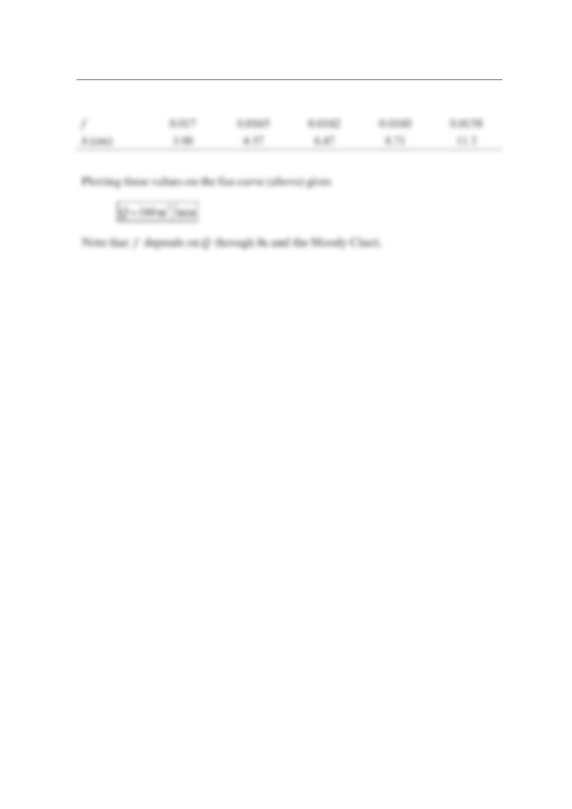
Using the Moody Chart and tabulating Re, ,
f
and
h
versus
Q
gives
Q (m3/min) 100 125 150 175 200
R2.9 × 1053.6 × 1054.3 × 1055.1 × 1055.8 × 105
f
Q
Problem 12.43
A model fan with wheel diameter
3
2 in.
is tested at a speed of 1750 rpm. The test fluid is air
with density 3
0.075 lbm/ft . At its BEP, the fan produces 3
8000 ft /min at total pressure rise
of 2
8 in.H O. A geometrically similar fan is to handle 3
200,000 ft /min of flue gas with
density 3
0.050 lbm/ft and 2
30 in.H O total pressure rise. Determine the required size and
speed of the flue gas fan. Note any assumptions and/or limitations.
Solution 12.43
To avoid the need to solve simultaneous equations, begin with a scaling law based on
specific speed
Now the diameter can be determined using Eq. (12.32)
Problem 12.44
A fan is to produce a total pressure rise of 2
6in.H O and a flow of 3
4000 ft /min. Two
motors are available, 3550rpm and 1160 rpm. For each motor, specify the best (most
efficient) type of fan to use and sketch the impeller.
Solution 12.44
The key to selecting the type of turbomachine to use is the specific speed. Calculate the true
dimensionless specific speed
Problem 12.45
An inward-flow radial turbine (see the figure below) involves a nozzle angle,
α
1, of °
6
0 and
an inlet rotor tip speed, 1,U of
3
m/s. The ratio of rotor inlet to outlet diameters is
2
.0. The
absolute velocity leaving the rotor at section (2) is radial with a magnitude of 6m/s.
Determine the energy transfer per unit mass of fluid flowing through this turbine if the fluid
is (a) air, (b) water.
Solution 12.45
+
V
2
=
6 m/s
r
2
r
1
Section (1)
Section (2)
α
1
V
2
=
6 m/s
r
2
r
1
b
Section (1)
α
1
Problem 12.46
The frictionless converging stationary nozzle of the hydraulic turbine shown in the figure
below has an inlet pressure =
0 480 kPa,p a negligible inlet velocity 0,
V
and an exit
pressure =
1 101kPa.p The velocity 1
V
is used to drive the axial flow turbine, which has a
rotational speed of 185.7rpm, an outside radius of = 1.20 m,R and a blade height of
= 0.40 m.h Determine velocities 1
V
and 2
V and the power transmitted to the turbine by the
water in terms of
α
1 and
α
2. The fluid density is constant and the velocities of the fluid
relative to the blade are directed as shown in the figure below. Assume that the velocities
are uniform over the flow inlet and outlet areas and use an average blade velocity at the
blade midheight =1.()00 mr and a water temperature of 20 °C
Solution 12.46
Assume no elevation changes and apply Bernoulli’s equation to the nozzle.
Nozzle
Nozzles
Section
AA
Blades
Flow area
V
O
,
p
O
U
AA
R
h
U
U
W
2
W
1
V
2
p
1
p
2
=
p
1
V
1
ω
ω
2
β
1
β
′
2
β
′
1
β
1
α
1
α
2
α
+
V
Or
The velocity 2
V can be found only as a function of the angles
αα
ββ
121 2
,,,and since their
values are not given. We start by applying the continuity equation to a control volume
enclosing the turbine rotor.
The power transmitted by the water to the turbine rotor is
The numerical values give
And

Or
Comment Now that we have developed this expression for s
W
as a function of
α
α
12
and , we
could determine the values of
α
α
12
and to maximize s
W
. The maximum value of power
would be obtained with the largest value of
α
1 and the lowest value of
α
2 that would allow
the flowrate through the turbine to be maintained.
Problem 12.47
A water turbine wheel rotates at the rate of 100 rpm in the direction shown in the figure
below. The inner radius, 2,r of the blade row is 1ft, and the outer radius, 1,r is 2 ft. The
absolute velocity vector at the turbine rotor entrance makes an angle of 20 with the
tangential direction. The inlet blade angle is 60° relative to the tangential direction. The
blade outlet angle is 120°. The flowrate is 3
10 ft /s. For the flow tangent to the rotor blade
surface at inlet and outlet, determine an appropriate constant blade height, ,
b
and the
corresponding power available at the rotor shaft. Is the shaft power greater or less than the
power lost by the fluid? Explain. See Section 12.3, Basic Angular Momentum
Considerations.
Solution 12.47
Note that the shaft power calculated below,
W
shaft ,
⋅
is less than the power lost by the fluid
because some of the power lost by the fluid is used to overcome fluid and shaft bearing
friction while the rest is delivered at the shaft.
100 rpm
V
1
+
20°
r
1
=
2 ft
60°
120°
W
1
W
2
r
2
=
1 ft
Section (2)
Section (1)
b
Also,
θ
=+ = + =
111
ft
sin30 20.9 11.12sin30 26.5 and
s
VUW
From the Law of Cosines (see figure):
Thus,
θ
=− =−
2
ft
10.47 22.2sin30 0.63 and becomes
V
Problem 12.48
A sketch of the arithmetic mean radius blade sections of an axial-flow water turbine stage is
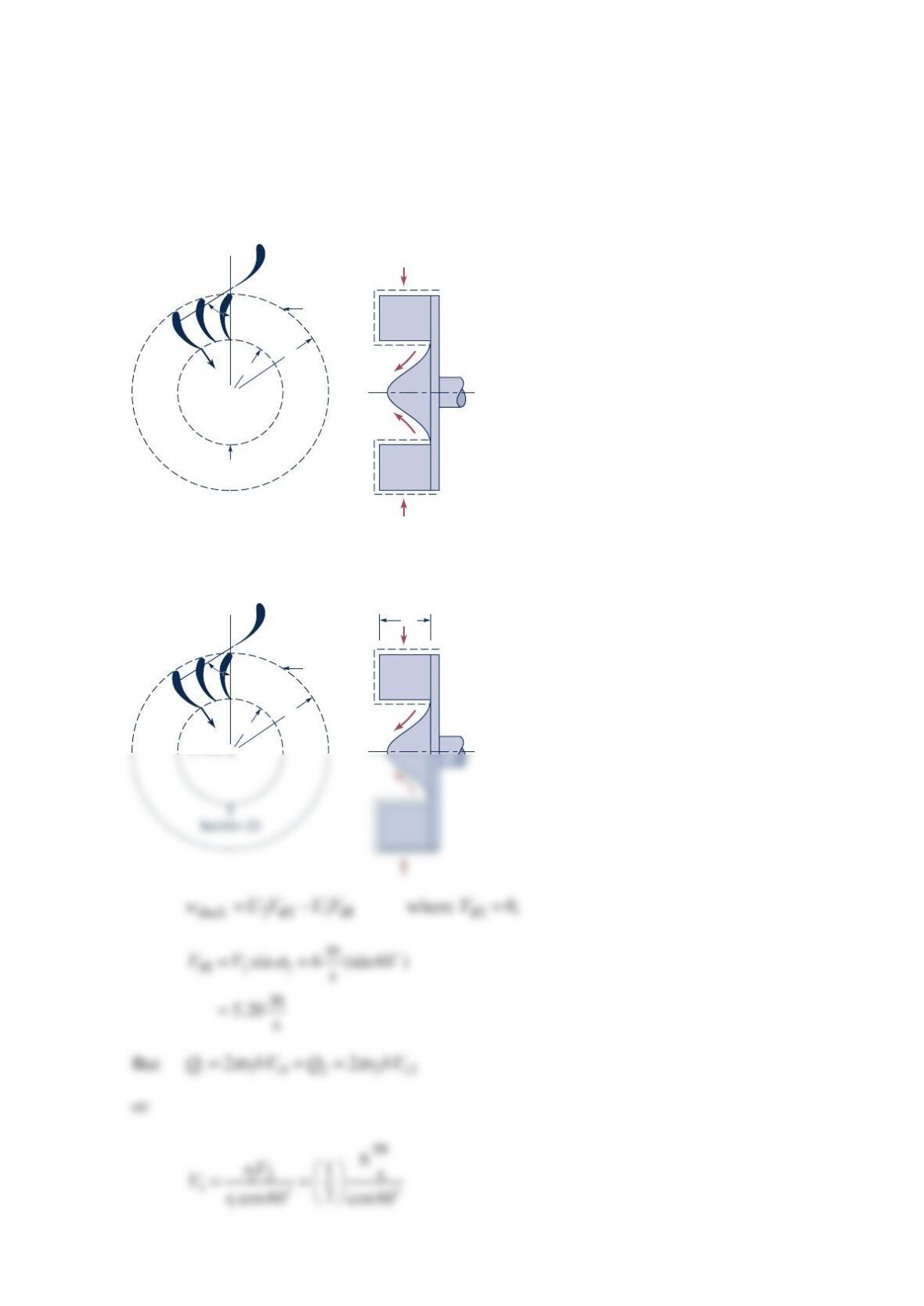
shown in the figure below. The rotor speed is 1500 rpm. (a) Sketch and label velocity
triangles for the flow entering and leaving the rotor row. Use
V
for absolute velocity,
W
for
relative velocity, and
U
for blade velocity. Assume flow enters and leaves each blade row at
the blade angles shown. (b) Calculate the work per unit mass delivered at the shaft.
Solution 12.48
(a)
π
ωω ω
== = =
11 2 2
rev 1min 2 rad rad
where 1500 157
min 60s rev s
Ur U r
(b)
()
θθ θθ
=−= −
shaft 2 2 1 1 2 1
w UVUVUVV
(1)
From the figures: =
11
cos 70 cos 45VW
1500
rpm
U
U
r
m = 6 in.
Stator Rotor
70°
45°45°
Blade sections
at the arithmetic
mean radius
Also,
θ
=− = − =
222
ft ft ft
sin 45 78.5 63.5 sin 45 33.6
ss s
VUW
Hence, from Eq. (1)
Problem 12.49
The figure below shows a piping system with frictional losses of L
h
Q2
12 4.0 ,
−= with L
h
12− in
f
t and
Q
in gal/min. The turbine performance characteristics are given by t
h
Q20 12.0 ,=+
where t
h
is the turbine head in
f
t and
Q
is in gal/min. Find the flowrate .Q
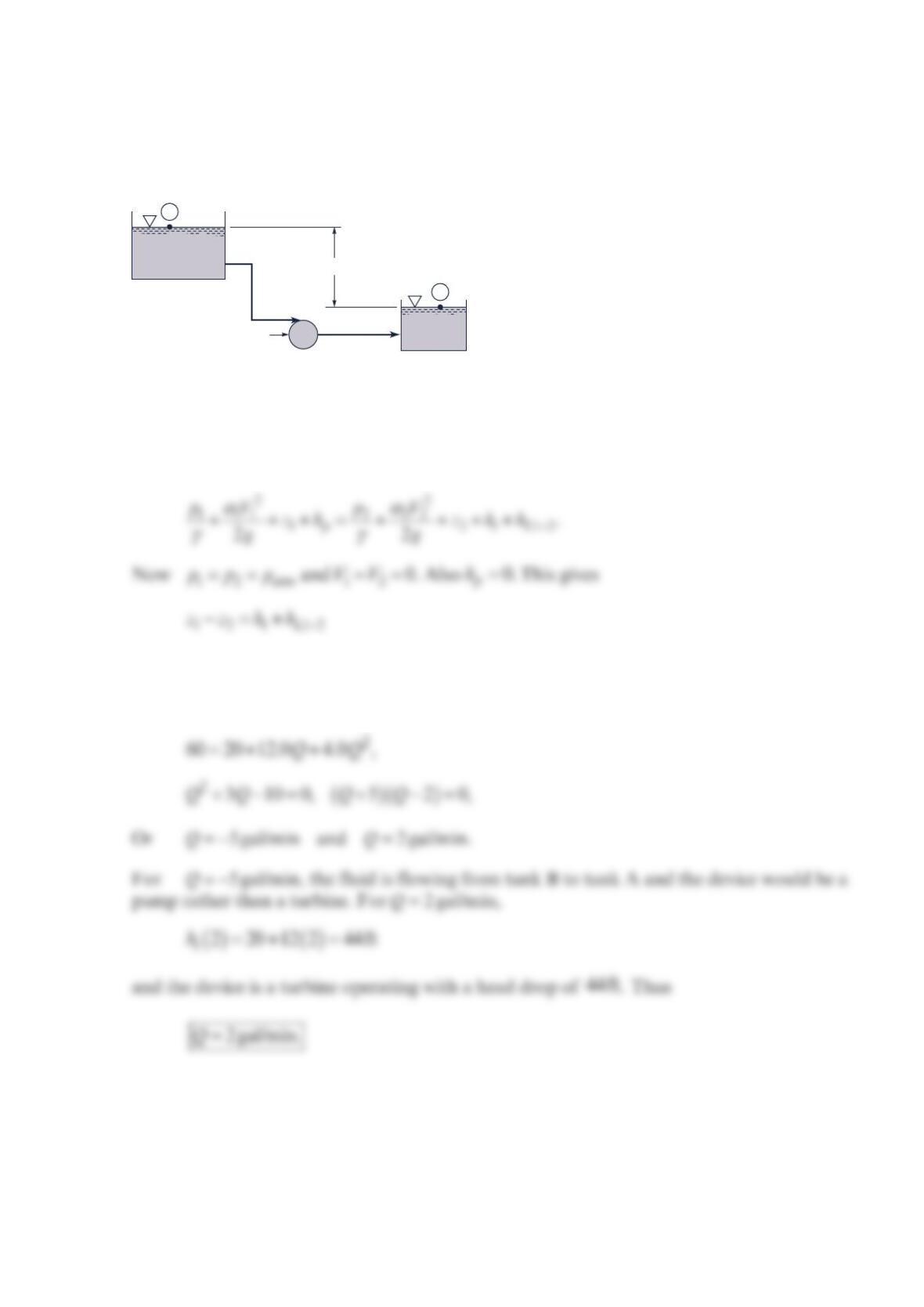
Solution 12.49
Assume constant fluid density and apply the mechanical energy equation from point (1) to
point (2).
Substituting the equation for t
h
and L
h
12− and noting
−==
12 60 ftzz h gives
A
h
= 60 ft
Turbine
1
B
2
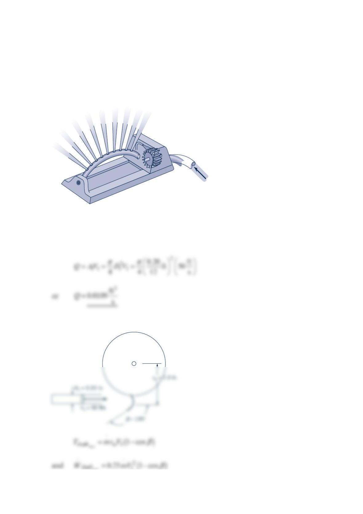
Problem 12.50
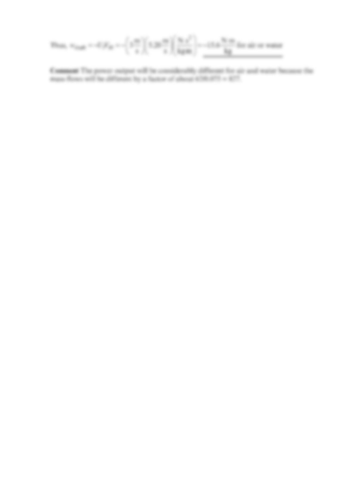
A small Pelton wheel is used to power an oscillating lawn sprinkler as shown in the figure
below. The arithmetic mean radius of the turbine is 1in. , and the exit angle of the blade is
°
1
35 relative to the blade motion. Water is supplied through a single 0.20-in.- diameter
nozzle at a speed of 50 ft/s . Determine the flowrate, the maximum torque developed, and
the maximum power developed by this turbine.
Solution 12.50
For the Pelton wheel shown
From the figure below
max
Q