
PROBLEM 12.31
KNOWN: Incandescent sphere suspended in air within a darkened room exhibiting these
characteristics:
initially: brighter around the rim
after some time: brighter in the center
FIND: Plausible explanation for these observations.
ASSUMPTIONS: (1) The sphere is at a uniform surface temperature, Ts.
ANALYSIS: Recognize that in observing the
Assume that the sphere is fabricated from a metallic material. Then, the rim would appear brighter
PROBLEM 12.32
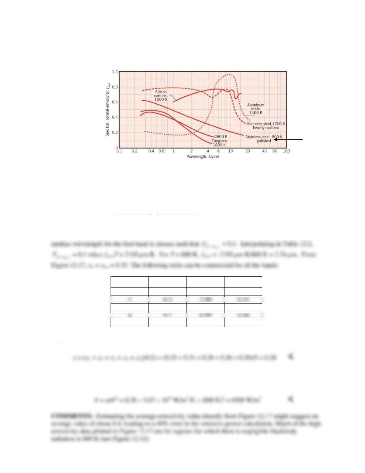
KNOWN: Temperature of polished stainless steel. Spectral emissivity distribution.
FIND: Total hemispherical emissivity using 5–band integration. Emissive power.
SCHEMATIC:
ASSUMPTIONS: Spectral hemispherical and normal emissivities are equal.
ANALYSIS: From Equation 12.43,
5
,55
,
01
( , , 1)
11
( ) (0.2)
i
ib
bi
i ii i
ii
bb
Ed
Ed
TF
EE
λ
λ
λλ
λλ
eλ
eλ
e ee
∞
∆
=→+
= =
= = = =
∑∫
∫∑∑
The last equality results from the choice that each band contains 20% of the blackbody emission. The
Band
(0 )
m
F
λ
→
λ
m (µm)
e
1
0.1
2.74
0.35
3
0.5
5.14
0.28
5
0.9
11.73
0.20
Thus,
The surface emissive power is
PROBLEM 12.33
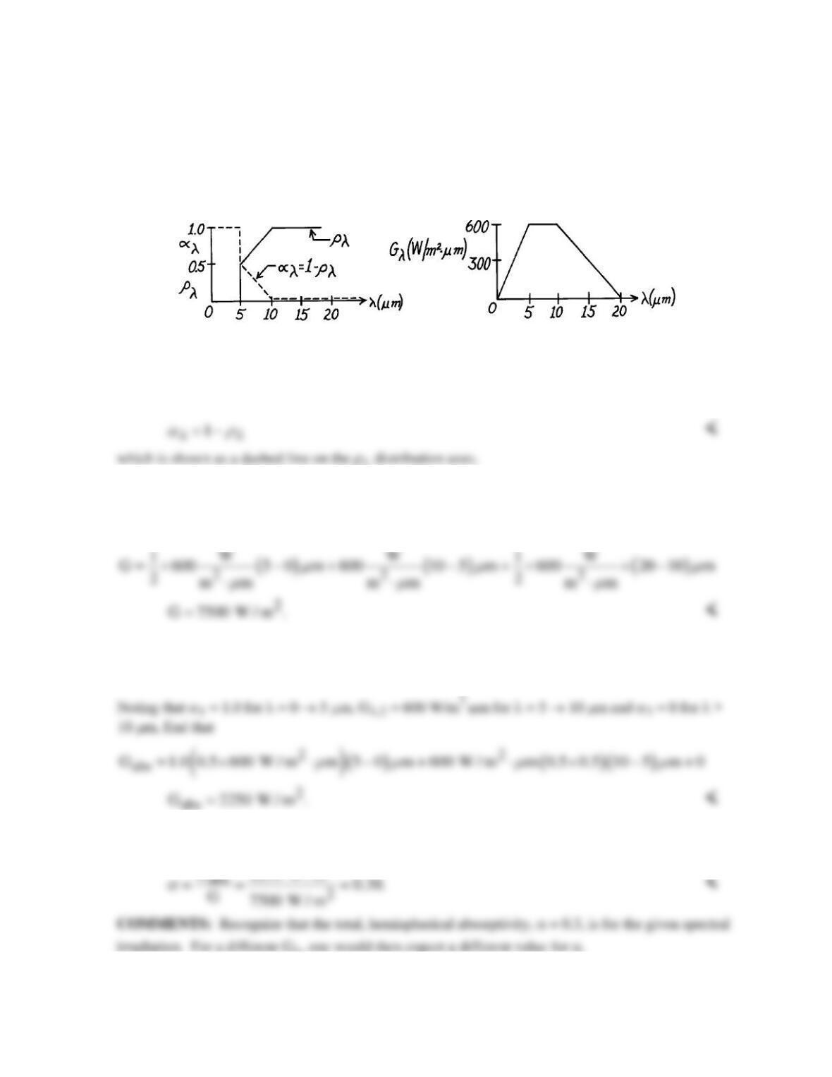
KNOWN: An opaque surface with prescribed spectral, hemispherical reflectivity distribution is
subjected to a prescribed spectral irradiation.
FIND: (a) The spectral, hemispherical absorptivity, (b) Total irradiation, (c) The absorbed radiant
flux, and (d) Total, hemispherical absorptivity.
SCHEMATIC:
ASSUMPTIONS: (1) Surface is opaque.
ANALYSIS: (a) The spectral, hemispherical absorptivity, αλ, for an opaque surface is given by Eq.
12.62,
(b) The total irradiation, G, follows from Eq. 12.19 which can be integrated by parts,
5 m 10 m 20 m
0 0 5 m 10 m
G Gd Gd Gd Gd
µµµ
λλ λ λ
µµ
λλ λ λ
∞
==++
∫∫ ∫ ∫
(c) The absorbed irradiation follows from Eqs. 12.51 and 12.52 with the form
5 m 10 m 20 m
abs 1 ,2 3
0 0 5 m 10 m
G Gd Gd G d Gd.
µ µµ
λλ λ λ λ λ
µµ
α λα λ α λα λ
∞
==++
∫∫ ∫ ∫
(d) The total, hemispherical absorptivity is defined as the fraction of the total irradiation that is
absorbed. From Eq. 12.51,
2
PROBLEM 12.34
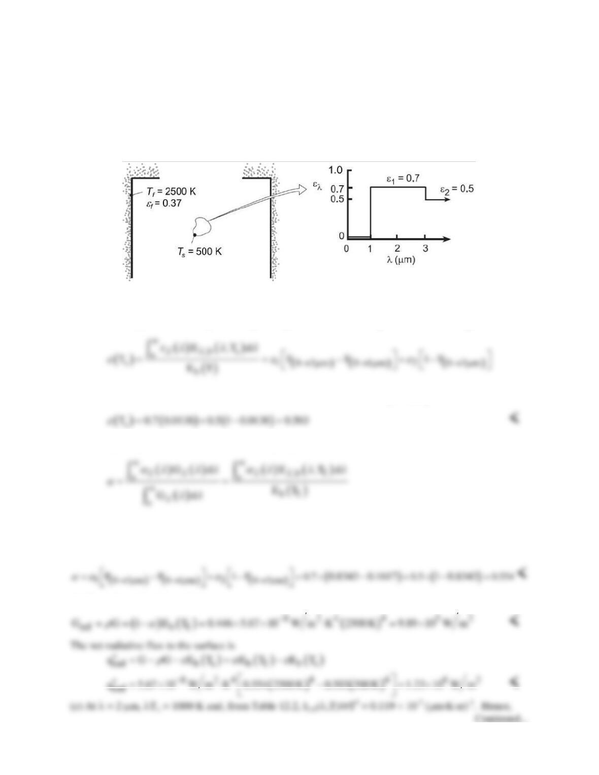
KNOWN: Temperature and spectral emissivity of small object suspended in large furnace of prescribed
temperature and total emissivity.
FIND: (a) Total surface emissivity and absorptivity, (b) Reflected radiative flux and net radiative flux to
surface, (c) Spectral emissive power at λ = 2 µm, (d) Wavelength λ1/2 for which one-half of total
emissive power is in spectral region λ ≥ λ1/2.
SCHEMATIC:
ASSUMPTIONS: (1) Surface is opaque and diffuse, (2) Walls of furnace are much larger than object.
ANALYSIS: (a) The emissivity of the object may be obtained from Eq. 12.43, which is expressed as
where, with λ1Ts = 500 µm⋅K and λ2Ts = 1500 µm⋅K, F(0→1µm) ≅ 0 and
( )
0 3m
F
µ
→
= 0.0138. Hence,
The absorptivity of the surface is determined by Eq. 12.52,
Hence, with λ1Tf = 2500 µm⋅K and λ2Tf = 7500 µm⋅K, F(0→1µm) = 0.1617 and
( )
0 3m
F
µ
→
= 0.8343. It
follows that
(b) The reflected radiative flux is
PROBLEM 12.34 (Cont.)
(d) There is negligible emission at wavelengths shorter than 3 µm. Hence, the total emissivity is nearly
independent of the spectral emissivities for λ < 3 µm. From Table 12.2, F(0→λ) = 0.5 corresponds to λTs ≈
4100 µm⋅K, in which case,
PROBLEM 12.35
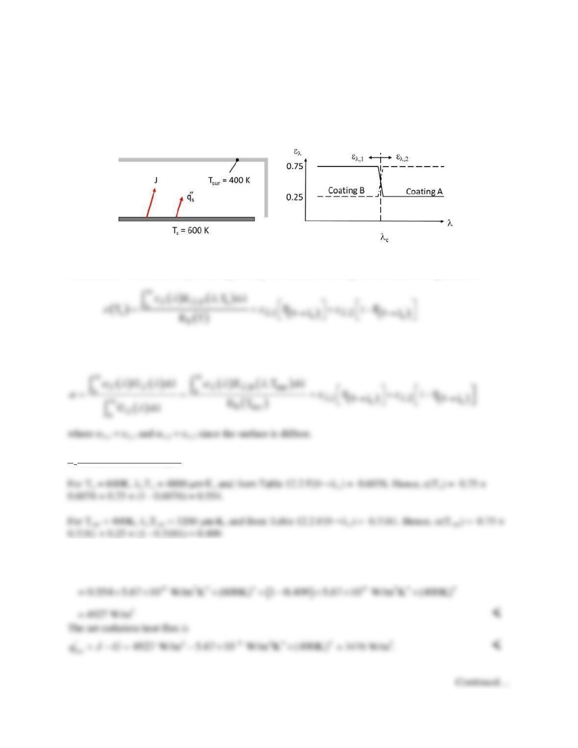
KNOWN: Spectral emissivities of thin coatings and metal plate. Cutoff wavelength, plate and
surroundings temperatures.
FIND: Radiosity and net radiation heat flux for cutoff wavelengths of λc = 8 and 6 µm. Which coating
yields largest net radiation flux.
SCHEMATIC:
ASSUMPTIONS: (1) Surface is opaque and diffuse, (2) Surroundings are large.
ANALYSIS: The emissivity of the object may be obtained from Eq. 12.43, which is expressed as
The absorptivity of the surface is determined by Eq. 12.52,
λc = 8 µm Case, Coating A
The radiosity is
( )
44
sur
1
s
JE G T T
r es α s
=+ = +−
PROBLEM 12.35 (Cont.)
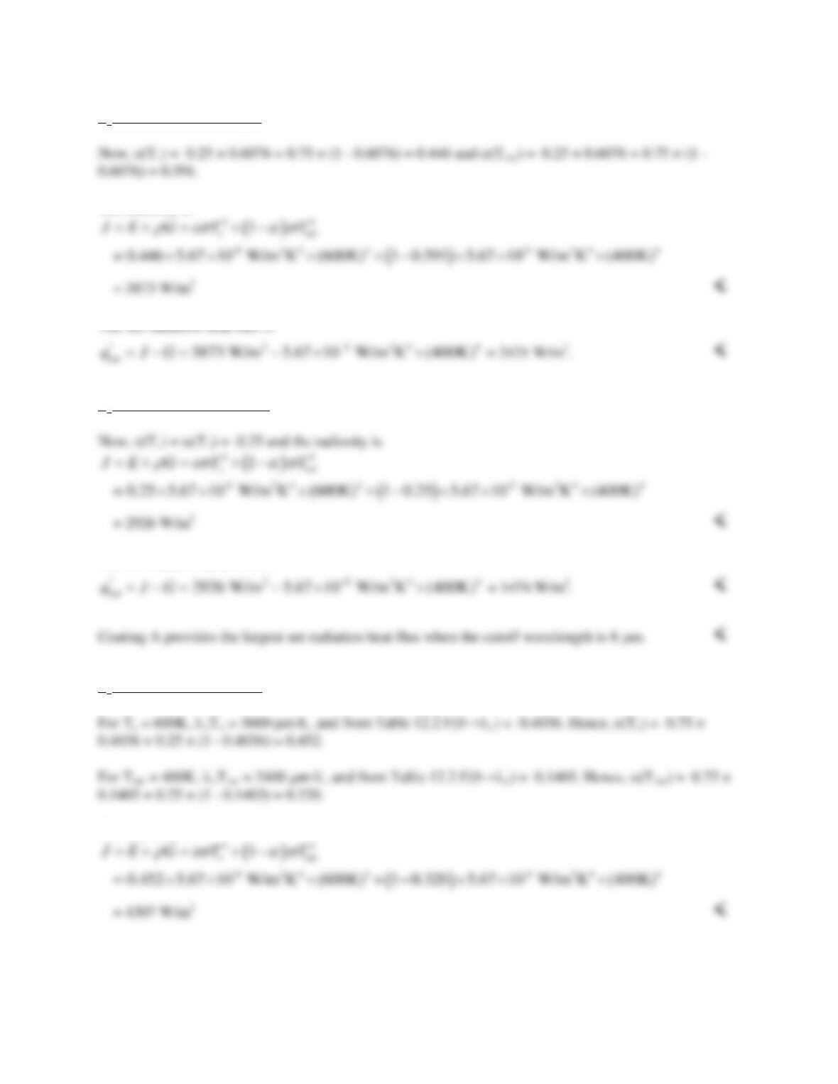
λc = 8 µm Case, Coating B
The radiosity is
λc = 8 µm Case, No Coating
The net radiation heat flux is
λc = 6 µm Case, Coating A
The radiosity is
Continued…
PROBLEM 12.35 (Cont.)
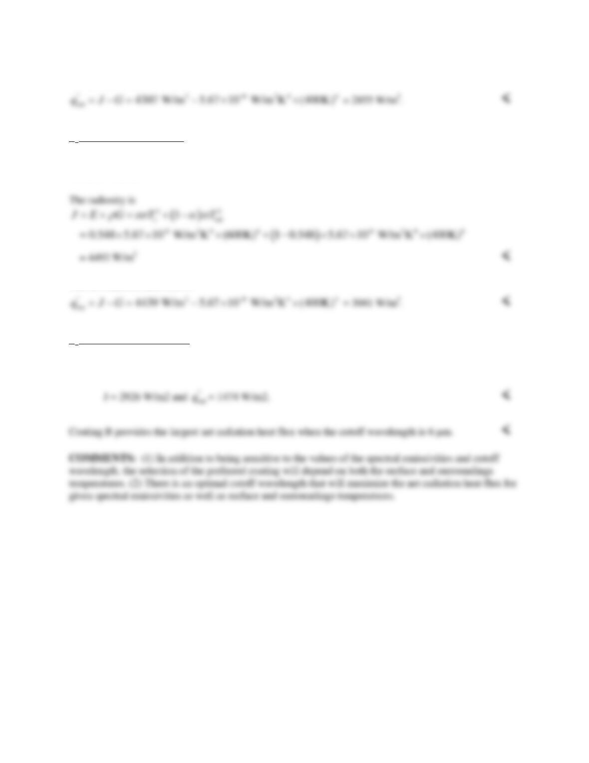
The net radiation heat flux is
λc = 6 µm Case, Coating B
Now, e(Ts) = 0.25 × 0.4036 + 0.75 × (1 – 0.4036) = 0.548 and α(Tsur) = 0.25 × 0.1402 + 0.75 × (1 –
0.1403) = 0.548.
The net radiation heat flux is
λc = 6 µm Case, No Coating
The radiosity and net radiation heat flux are the same as for the 8 µm cutoff wavelength coating:
PROBLEM 12.36
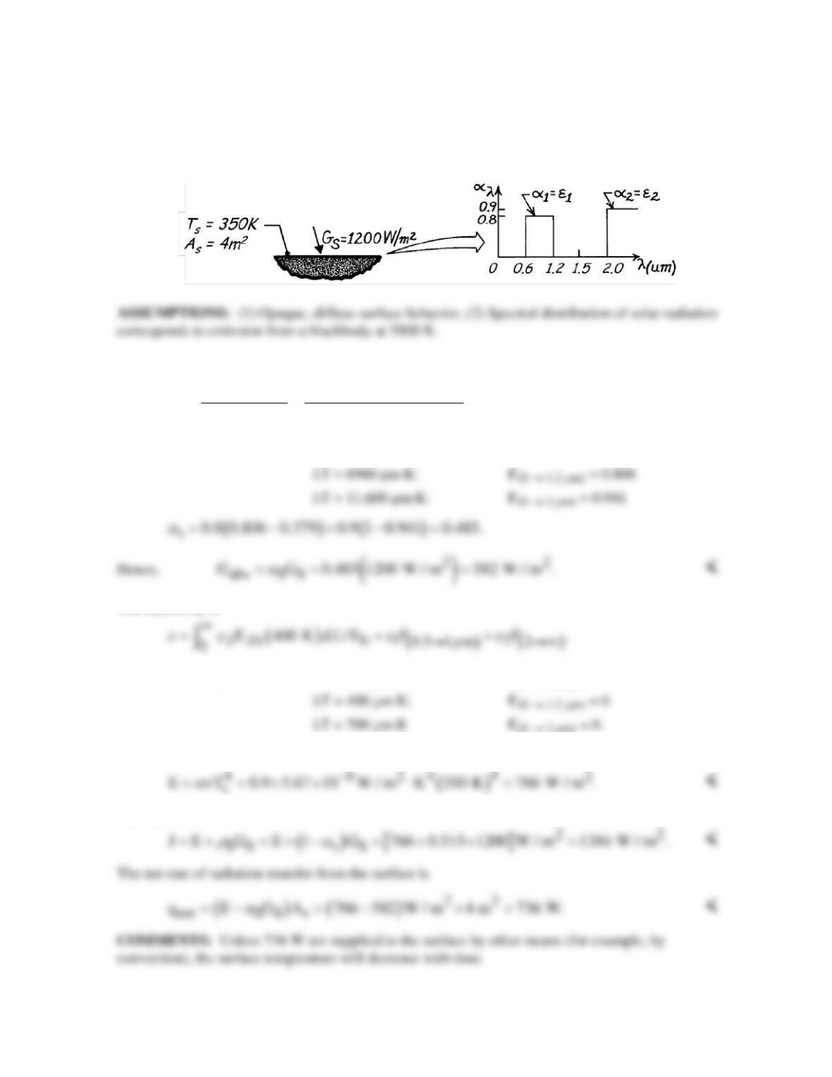
KNOWN: Area, temperature, irradiation and spectral absorptivity of a surface.
FIND: Absorbed irradiation, emissive power, radiosity and net radiation transfer rate from the
surface.
SCHEMATIC:
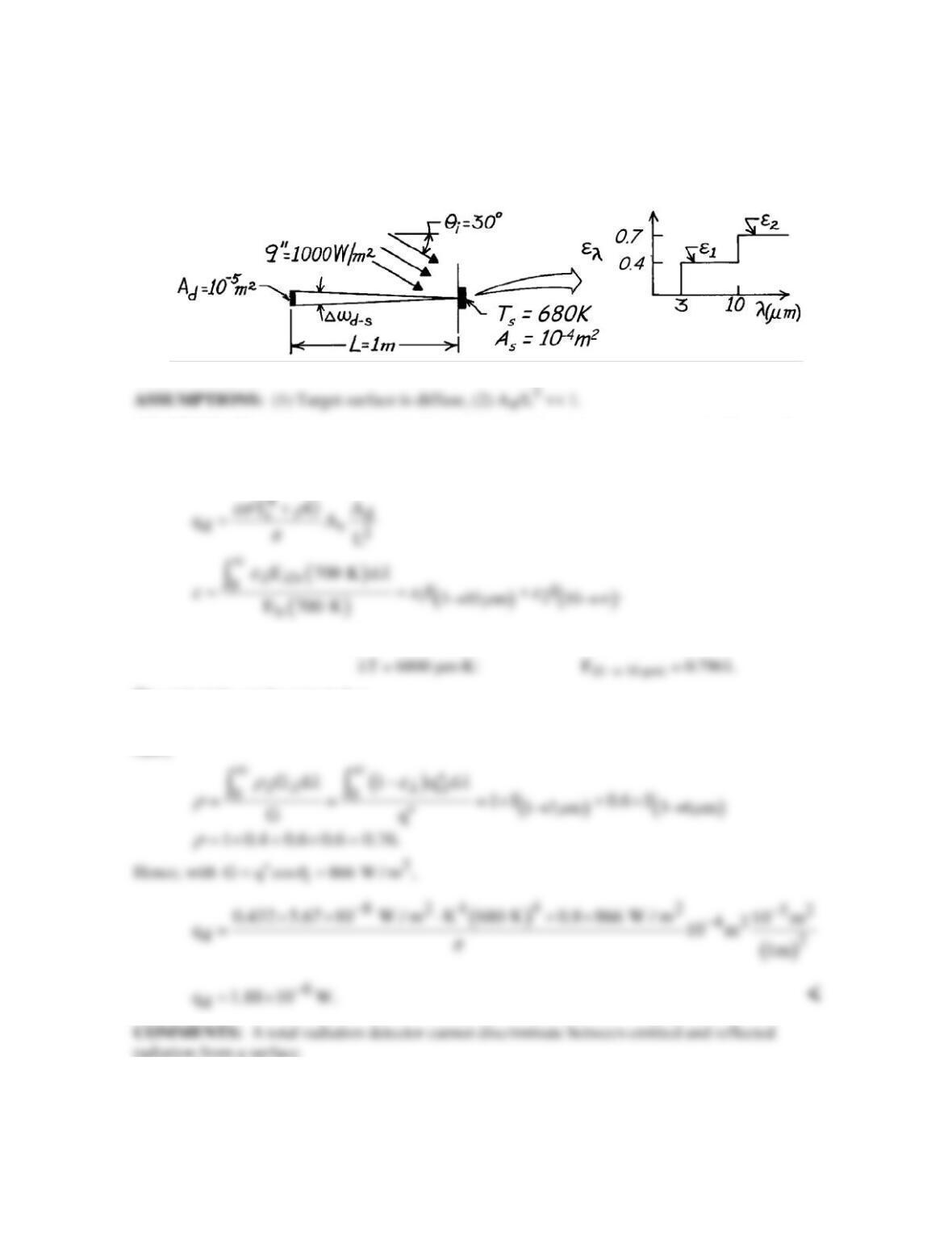
ANALYSIS: The absorptivity to solar irradiation is
( )
( ) ( )
b
00
s 12
0.5 1 m 2
b
G d E 5800 K d
F F.
GE
λλ λλ
µ
αλ α λ
α αα
∞∞
→ →∞
= = = +
∫∫
From Table 12.2, λT = 3480 µm⋅K: F(0 → 0.6 µm) = 0.379
The emissivity is
From Table 12.2, λT = 210 µm⋅K: F(0 → 0.6 µm) = 0
Hence, e = e2 = 0.9,
The radiosity is
PROBLEM 12.37
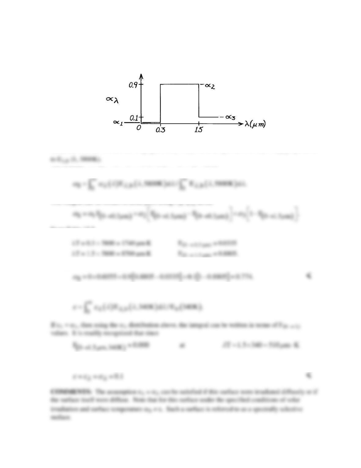
KNOWN: Temperature and spectral emissivity of a receiving surface. Direction and spectral
distribution of incident flux. Distance and aperture of surface radiation detector.
FIND: Radiant power received by the detector.
SCHEMATIC:
ANALYSIS: The radiant power received by the detector depends on emission and reflection from
the target.
d er s ds ds
q I A cos
θω
+ −−
= ∆
From Table 12.2, λT = 2040 µm⋅K: F(0 → 3 µm) = 0.0736
The emissivity can be expected as
( ) ( )
0.4 0.7961 0.0736 0.7 1 0.7961 0.432.
e
= − +− =
Also,
PROBLEM 12.38
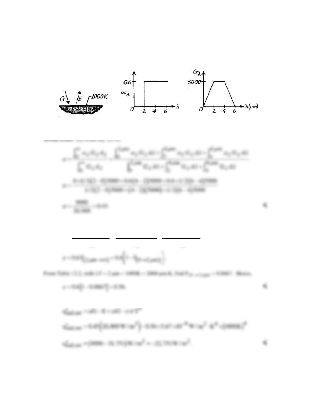
KNOWN: Spectral, hemispherical absorptivity of an opaque surface.
FIND: (a) Solar absorptivity, (b) Total, hemispherical emissivity for Ts = 340K.
SCHEMATIC:
ASSUMPTIONS: (1) Surface is opaque, (2) eλ = αλ, (3) Solar spectrum has Gλ = Gλ,S proportional
ANALYSIS: (a) The solar absorptivity follows from Eq. 12.53.
The integral can be written in three parts using F(0 → λ) terms.
From Table 12.2,
Hence,
(b) The total, hemispherical emissivity for the surface at 340K will be
there is negligible spectral emissive power below 1.5 µm. It follows then that
PROBLEM 12.39
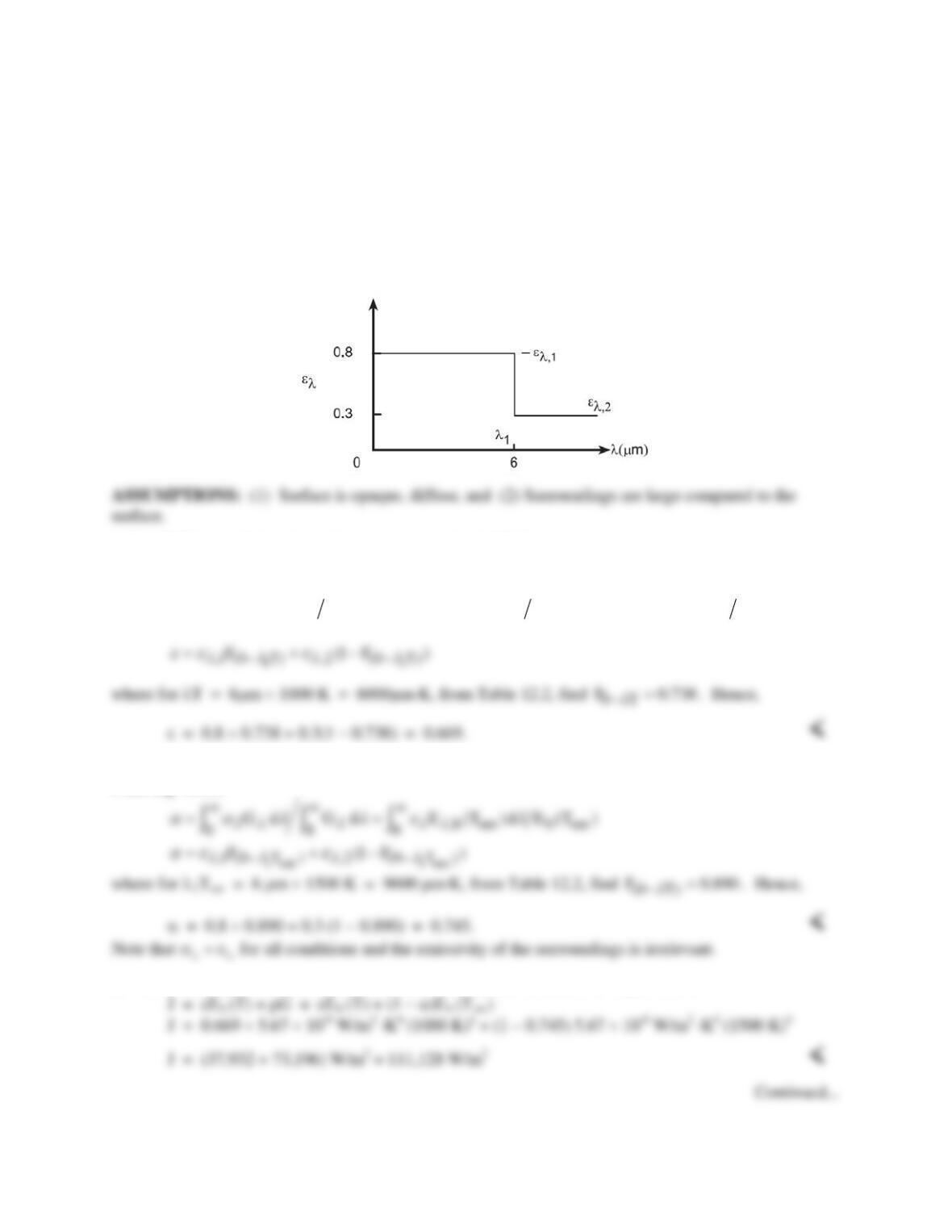
KNOWN: Spectral distribution of the absorptivity and irradiation of a surface at 1000 K.
FIND: (a) Total, hemispherical absorptivity, (b) Total, hemispherical emissivity, (c) Net radiant flux
to the surface.
SCHEMATIC:
ASSUMPTIONS: (1) αλ = eλ.
(b) From Eq. 12.43,
2m
,b ,b ,b
00 2
bbb
Ed 0 Ed 0.6 E d
EEE
µ
λλ λ λ
eλ λ λ
e
∞∞
= = +
∫∫ ∫
(c) The net radiant heat flux to the surface is
PROBLEM 12.40
KNOWN: Spectral emissivity of an opaque, diffuse surface.
FIND: (a) Total, hemispherical emissivity of the surface when maintained at 1000 K, (b) Total,
hemispherical absorptivity when irradiated by large surroundings of emissivity 0.8 and temperature 1500
K, (c) Radiosity when maintained at 1000 K and irradiated as prescribed in part (b), (d) Net radiation
flux into surface for conditions of part (c), and (e) Compute and plot each of the parameters of parts (a)-
(c) as a function of the surface temperature Ts for the range 750 < Ts ≤ 2000 K.
SCHEMATIC:
ANALYSIS: (a) When the surface is maintained at 1000 K, the total, hemispherical emissivity is
evaluated from Eq. 12.43 written as
1
,b b ,1 ,b b ,2 ,b b
0 01
E (T) d E (T) E (T) d E (T) E (T) d E (T)
λ
λλ λ λ λ λ
λ
ee λ e λ e λ
∞∞
= = +
∫ ∫∫
(b) When the surface is irradiated by large surroundings at Tsur = 1500 K, G = Eb(Tsur).
From Eq. 12.52,
(c) The radiosity for the surface maintained at 1000 K and irradiated as in part (b) is
PROBLEM 12.40 (Cont.)
(d) The net radiation flux into the surface with
G Tsur
= s 4
is
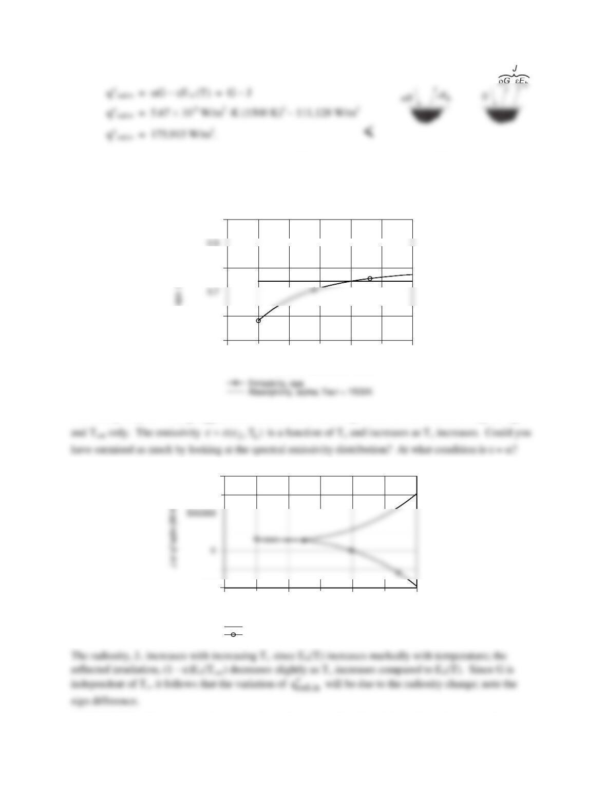
(e) The foregoing equations were entered into the IHT workspace along with the IHT Radiaton Tool,
Band Emission Factor, to evaluate
FT( )0
−λ values and the respective parameters for parts (a)–(d) were
computed and are plotted below.
500 1000 1500 2000
Surface temperature, Ts (K)
0.5
0.6
0.8
1
The absorptivity,
sur
( ,T )
λ
α αα
=
, remains constant as Ts changes since it is a function of
(or )
λλ
αe
500 1000 1500 2000
Surface temperature, Ts (K)
-5E5
1E6
Radiosity, J (W/m^2)
Net radiation flux in, q”radin (W/m^2)
COMMENTS: We didn’t use the emissivity of the surroundings (e = 0.8) to determine the irradiation
onto the surface. Why?

PROBLEM 12.41
KNOWN: Approximate spectral transmissivity of 1–mm thick liquid water layer.
FIND: (a) Transmissivity of a 1–mm thick water layer adjacent to surface at the critical
temperature (Ts = 647.3 K), (b) Transmissivity of a 1-mm thick water layer subject to irradiation
from a melting platinum wire (Ts = 2045 K), (c) Transmissivity of a 1-mm thick water layer
subject to solar irradiation at Ts = 5800 K.
SCHEMATIC:
ASSUMPTIONS: Irradiation is proportional to that of a blackbody.
ANALYSIS: From Eq. 12.61 and incorporating the assumption, the transmissivity is expressed as
1.2 1.8
,b ,1 ,b ,2 ,b ,3 ,b
0 0 1.2 1.8
bb b b
Ed Ed Ed Ed
EE E E
∞∞
λλλλλλλλ
τ λτ λτ λτ λ
τ= = + +
∫ ∫∫∫
or
(b) For a source temperature of 2045 K,
(c) For a source temperature of 5800 K,
COMMENTS: Liquid water may be treated as opaque for most engineering applications.
λ(µm)
τ
λ
0 1 1.2 1.8 2
1.0
0.5
0
τλ,1 = 0.99
τλ,2 = 0.54
τλ,3 = 0
λ(µm)
τ
λ
0 1 1.2 1.8 2
1.0
0.5
0
τλ,1 = 0.99
τλ,2 = 0.54
τλ,3 = 0
PROBLEM 12.42
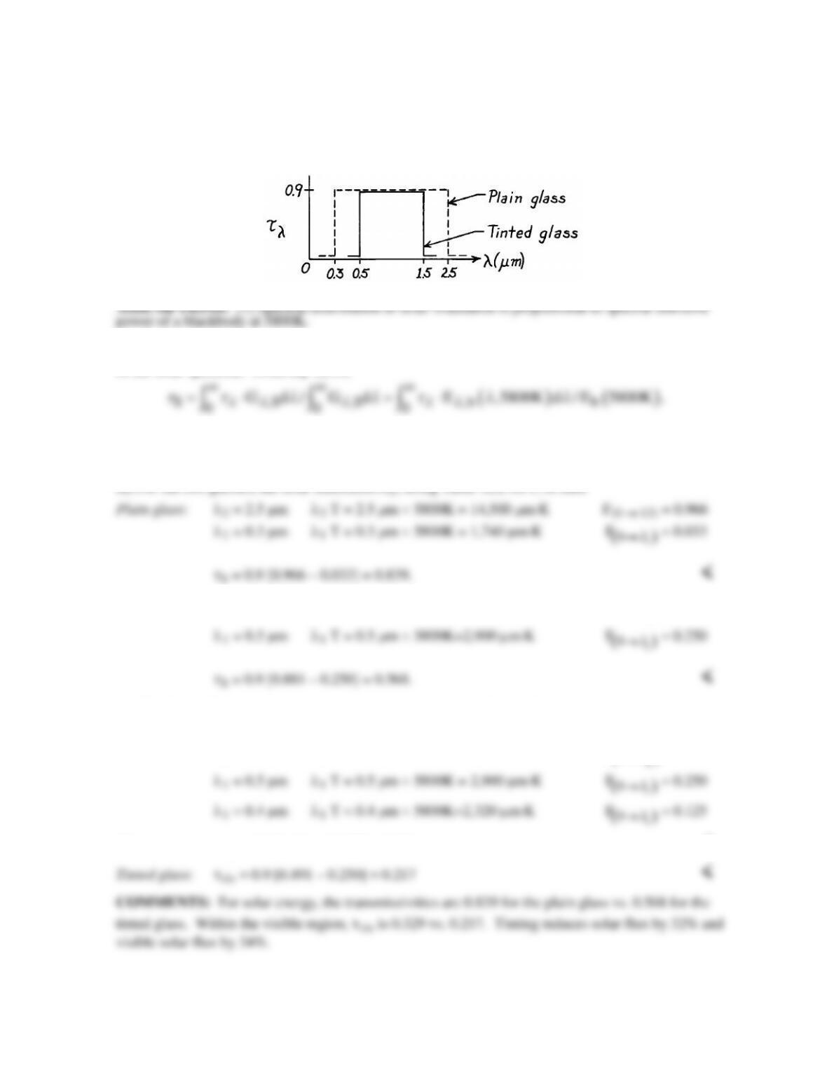
KNOWN: Spectral transmissivity of a plain and tinted glass.
FIND: (a) Solar energy transmitted by each glass, (b) Visible radiant energy transmitted by each with
solar irradiation.
SCHEMATIC:
ANALYSIS: To compare the energy transmitted by the glasses, it is sufficient to calculate the
transmissivity of each glass for the prescribed spectral range when the irradiation distribution is that
of the solar spectrum. From Eq. 12.61,
Recognizing that τλ will be constant for the range λ1 →λ2, using Eq. 12.29, find
( ) ( ) ( )
12 2 1
S00
F F F.
λλ
λλ λ λ
ττ τ
→ →→
=⋅= −
Tinted glass: λ2 = 1.5 µm λ2 T = 1.5 µm × 5800K = 8,700 µm⋅K
( )
2
0
F 0.881
λ
→
=
(b) The limits of the visible spectrum are λ1 = 0.4 and λ2 = 0.7 µm. For the tinted glass, λ1 = 0.5 µm
rather than 0.4 µm. From Table 12.2,
λ2 = 0.7 µm λ2 T = 0.7 µm × 5800K = 4,060 µm⋅K
( )
2
0
F 0.491
λ
→
=
Plain glass: τvis = 0.9 [0.491 – 0.125] = 0.329 <
PROBLEM 12.43
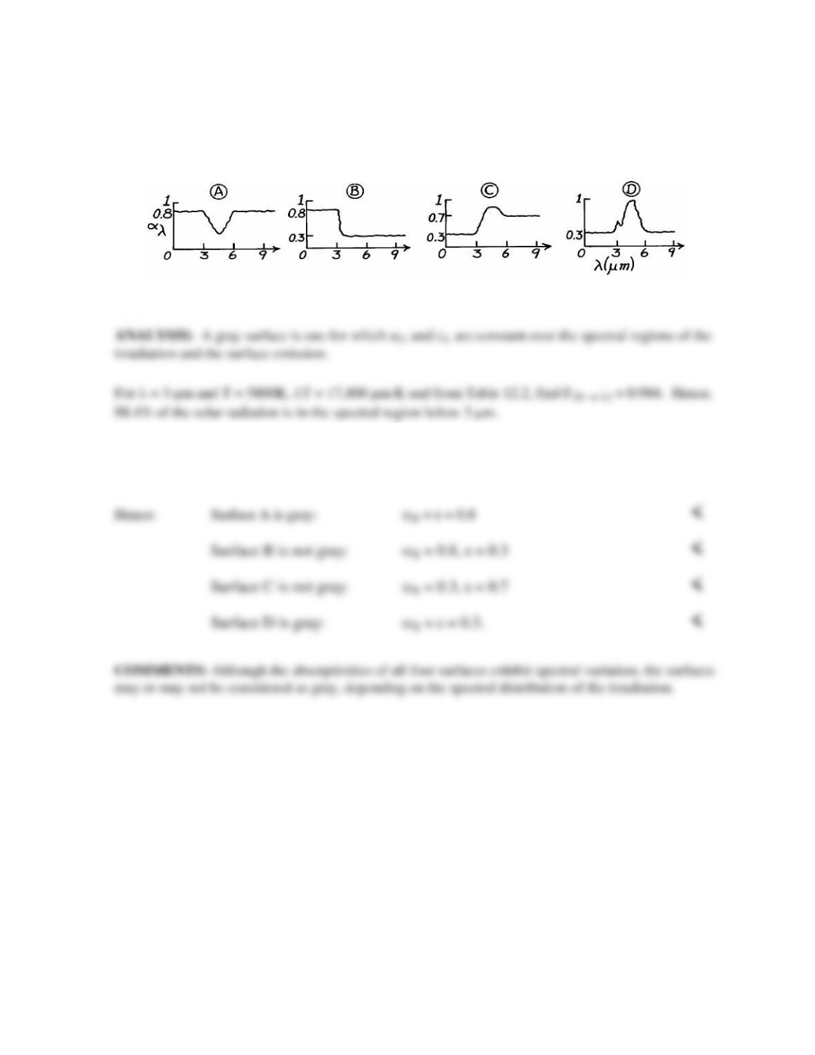
KNOWN: Spectral characteristics of four diffuse surfaces exposed to solar radiation.
FIND: Surfaces which may be assumed to be gray.
SCHEMATIC:
ASSUMPTIONS: (1) Diffuse surface behavior.
For λ = 6 µm and T = 300K, λT = 1800 µm⋅K and from Table 12.2, find F(0 → λ) = 0.039. Hence,
96.1% of the surface emission is in the spectral region above 6 µm.
PROBLEM 12.44
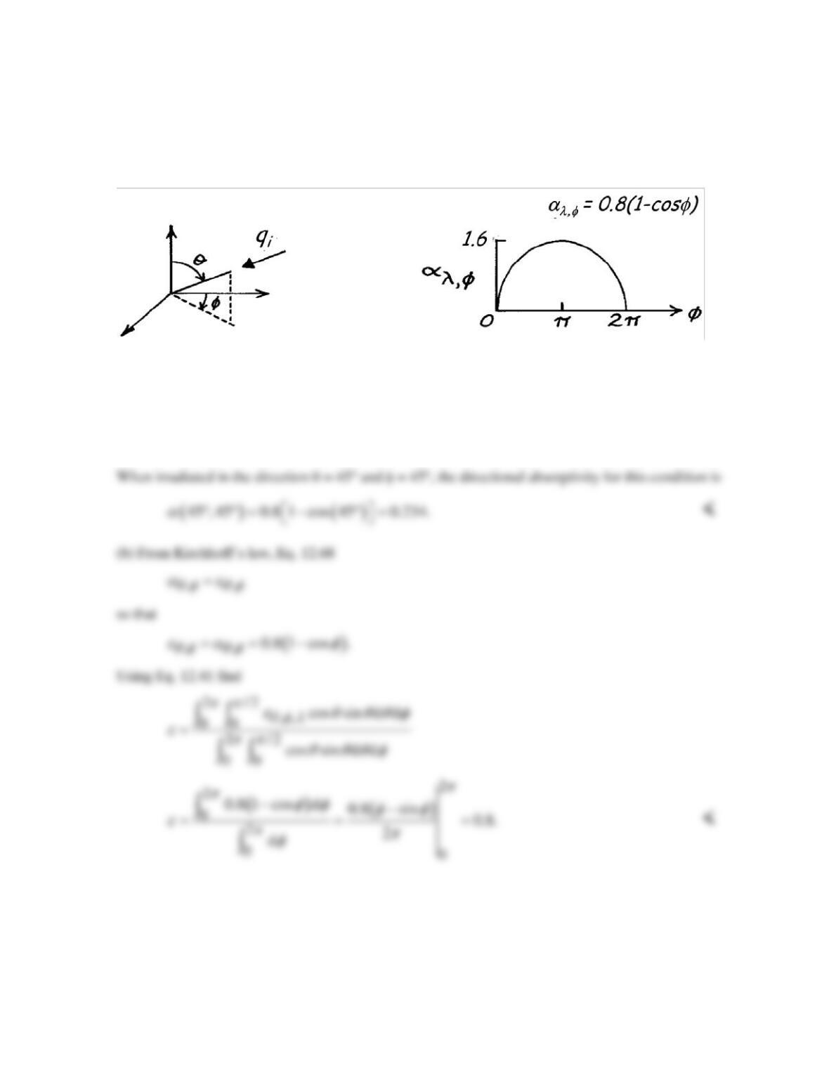
KNOWN: A gray, but directionally selective, material with α (θ, φ) = 0.8(1 – cosφ).
FIND: (a) Hemispherical absorptivity when irradiated with collimated flux in the direction (θ = 45°
and φ = 45°) and (b) Hemispherical emissivity of the material.
SCHEMATIC:
ASSUMPTIONS: (1) Gray surface behavior.
ANALYSIS: (a) The surface has the directional absorptivity given as
( )
[ ]
,
, 0.8 1 cos .
λφ
αθφ α φ
= = −
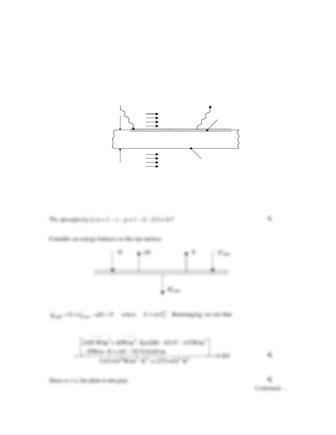
PROBLEM 12.45
KNOWN: Thickness, thermal conductivity and surface temperatures of a flat plate. Irradiation
on the top surface, reflected irradiation, air and water temperatures, air convection coefficient.
FIND: Transmissivity, reflectivity, absorptivity, and emissivity of the plate. Radiosity of the
surface. Convection coefficient associated with the water flow.
SCHEMATIC:
ASSUMPTIONS: (1) Opaque and diffuse surface, (2) Water is opaque to thermal radiation.
ANALYSIS: The plate is opaque. Therefore, τ = 0 <
The reflectivity is r = rG/G = (435 W/m2)/(1450 W/m2) = 0.3 <
” “4
conv cond t
(G q G q ) /( T )
e= + −r − s
L = 21 mm
G = 1450 W/m
2
rG = 435 W/m
2
k = 25 W/m·K
T
b
= 35°C
T
t
= 43°C
Water
T
∞,w
= 25°C
h
w
Air
T
∞,a
= 260°C
h
a
= 40 W/m
2
•K
L = 21 mm
G = 1450 W/m
2
rG = 435 W/m
2
k = 25 W/m·K
T
b
= 35°C
T
t
= 43°C
Water
T
∞,w
= 25°C
h
w
Air
T
∞,a
= 260°C
h
a
= 40 W/m
2
•K

PROBLEM 12.45 (Cont.)
The radiosity associated with the top surface is
COMMENTS: (1) The calculated emissivity is extremely sensitive to the plate thickness.