PROBLEM 12.73 (Cont.)
( )
2
i
3
dT 4 W
15.4 1500 300 K
kg J
dt mK
8933 385 0.01m
kg K
m
= −
⋅
⋅
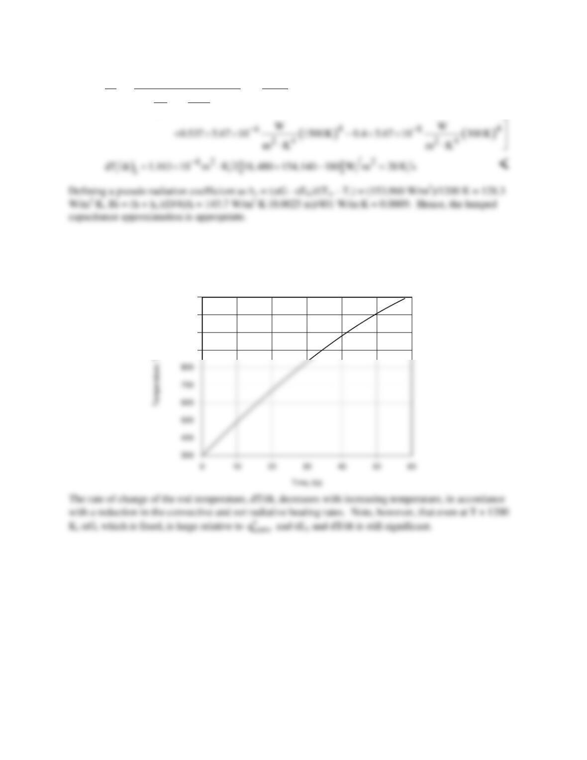
(c) Using the IHT Lumped Capacitance Model with the Correlations, Radiation and Properties (copper
and air) Toolpads, the transient response of the rod was computed for 300 ≤ T < 1200 K, where the upper
limit was determined by the temperature range of the copper property table.
900
1000
1100
1200
PROBLEM 12.74
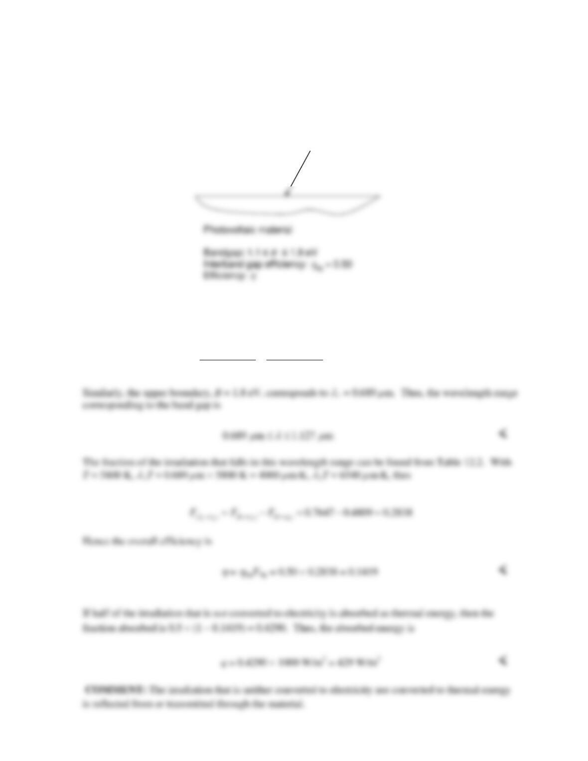
KNOWN: Bandgap of photovoltaic material. Relationship between wavelength and energy state of
photon. Inter-band gap efficiency. Half of incident photons not converted to electricity are absorbed
as thermal energy. Solar irradiation and associated blackbody temperature.
FIND: Wavelengths of solar irradiation corresponding to material’s band gap. Overall efficiency.
Heat absorption per unit surface area.
SCHEMATIC:
ASSUMPTIONS: Wavelength distribution of solar irradiation corresponds to a blackbody at 5800 K.
ANALYSIS: The lower boundary of the band-gap, B = 1.1 eV, corresponds to a wavelength of
2
1240 eV nm 1240 eV nm 1127 nm 1.127 m
1.1 eVB
λµ
⋅⋅
= = = =
G= 1000 W/m2
PROBLEM 12.75
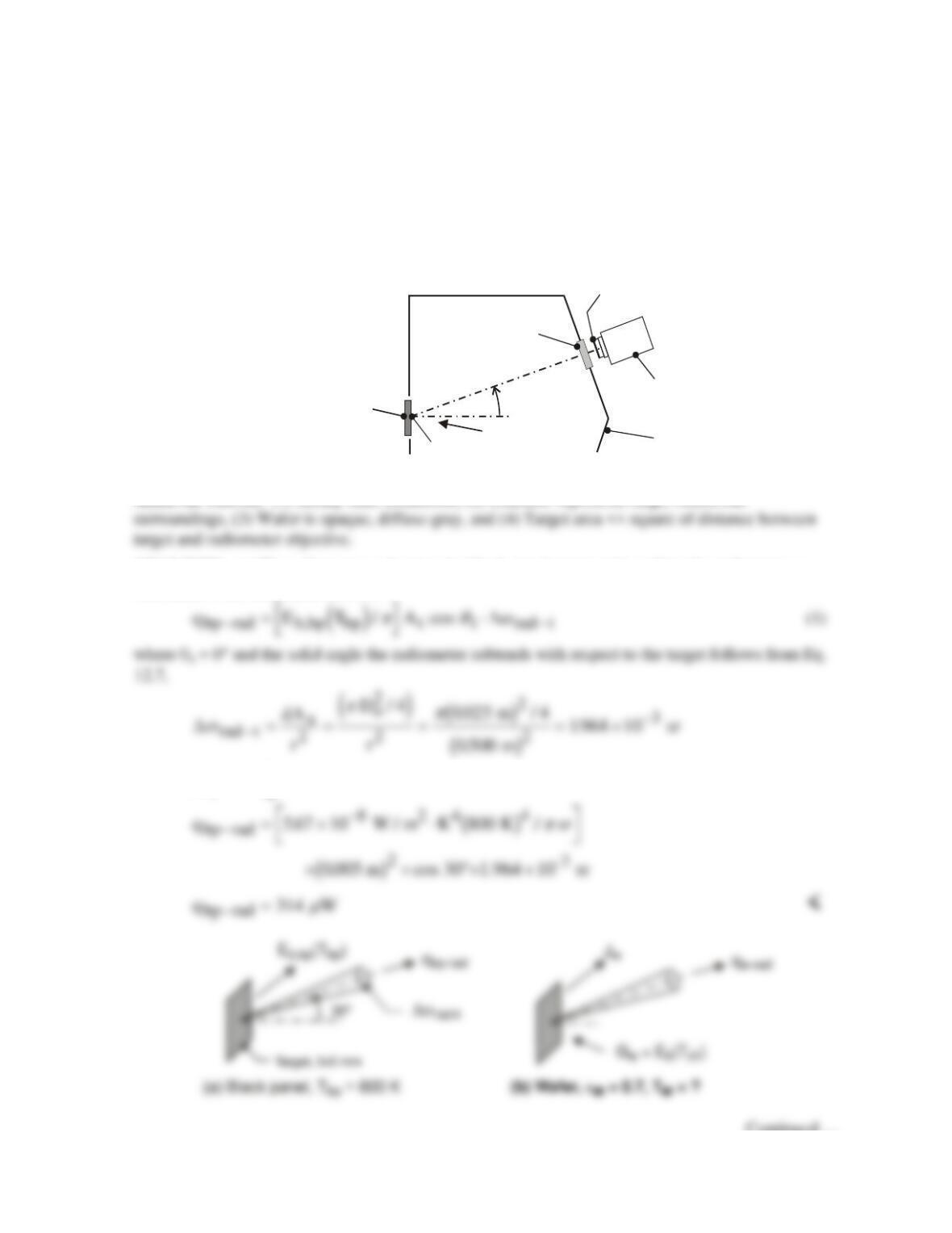
KNOWN: Wafer heated by ion beam source within large process–gas chamber with walls at uniform
temperature; radiometer views a 5 × 5 mm target on the wafer. Black panel mounted in place of wafer
in a pre-production test of the equipment.
FIND: (a) Radiant power (µW) received by the radiometer when the black panel temperature is Tbp
= 800 K and (b) Temperature of the wafer, Tw, when the ion beam source is adjusted so that the
radiant power received by the radiometer is the same as that of part (a)
SCHEMATIC:
Black panel, T = 800 K
Wafer, = 0.7, T = ?
bp
ε
w
Target, 5×5 mm
Chamber,
Tch = 400 K
500 mm
Radiometer
Ion beam
30
o
Window
Objective, 25 mm dia
ASSUMPTIONS: (1) Steady-state conditions, (2) Chamber represents large, isothermal
ANALYSIS: (a) The radiant power leaving the black–panel target and reaching the radiometer as
illustrated in the schematic below is
With
E T
b,bp bp
4
=
s
,
find
Continued …

PROBLEM 12.75 (Cont.)
(b) With the wafer mounted, the ion beam source is adjusted until the radiometer receives the same
radiant power as with part (a) for the black panel. The power reaching the radiometer is expressed in
terms of the wafer radiosity,
q J A cos
wrad w t t rad t− −
= ⋅/
π q ω
∆
(2)
Since
q q
wrad bp rad− −
=
(see Eq. (1)), recognize that
COMMENTS: (1) Explain why Tw is higher than 800 K, the temperature of the black panel, when
the radiometer receives the same radiant power for both situations.
PROBLEM 12.76
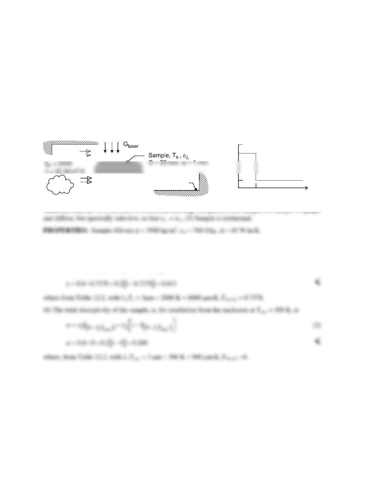
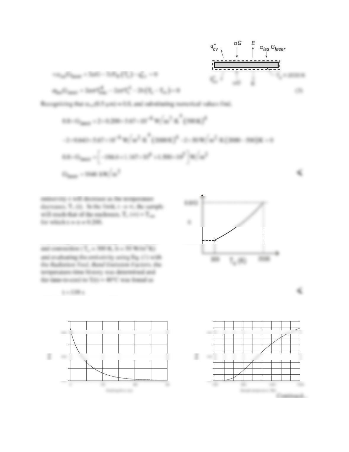
KNOWN: Laser–materials–processing apparatus. Spectrally selective sample heated to the operating
temperature Ts = 2000 K by laser irradiation ( 0.5 µm ), Glaser, experiences convection with an inert gas
and radiation exchange with the enclosure.
FIND: (a) Total emissivity of the sample, ε ; (b) Total absorptivity of the sample, α, for irradiation from
the enclosure; (c) Laser irradiation required to maintain the sample at Ts = 2000 K by performing an
energy balance on the sample; (d) Sketch of the sample emissivity during the cool-down process when
the laser and inert gas flow are deactivated; identify key features including the emissivity for the final
condition (t →
∞
); and (e) Time–to–cool the sample from the operating condition at Ts (0) = 2000 K to a
safe–to–touch temperature of Ts (t) = 40°C; use the lumped capacitance method and include the effects of
convection with inert gas (
T∞
= 300 K , h = 50 W/ m2⋅K) as well as radiation exchange Tenc =
T
∞
.
SCHEMATIC:
0.8
0.2
03
λ µ
( m)
ε
λ
ε
1
ε
2
Inert
gas
T = 300 K
enc
ANALYSIS: (a) The total emissivity of the sample, ε, at Ts = 2000 K follows from Eq. 12.43 which can
be expressed in terms of the band emission factor, F(0–λ,T) Eq. 12.34,
( ) ( )
1s 1s
12
0T 0T
F 1F
λλ
εε ε
−−
= +−
(1)
Continued…
PROBLEM 12.76 (Cont.)
(c) The energy balance on the sample, on a per unit area
basis, as shown in the schematic at the right is
in out
EE 0−=
(d) During the cool-down process, the total
(e) Using the IHT Lumped Capacitance Model
considering radiation exchange (Tenc = 300 K)
0.200
COMMENTS: (1) From the IHT model used for part (e), the emissivity as a function of cooling time and sample
temperature were computed and are plotted below. Compare these results to your sketch of part (c).
0.3
0.5
0.7
0.3
0.5
0.7

PROBLEM 12.76 (Cont.)
(2) The IHT workspace model to perform the lumped capacitance analysis with variable emissivity is
shown below.
// Lumped Capacitance Model – convection and emission/irradiation radiation processes:
/* Conservation of energy requirement on the control volume, CV. */
Edotin – Edotout = Edotst
/* The independent variables for this system and their assigned numerical values are */
As = 2 * 1 // surface area, m^2; unit area, top and bottom surfaces
vol = 1 * w // vol, m^3
// Radiation Tool – Band emission factor:
PROBLEM 12.77
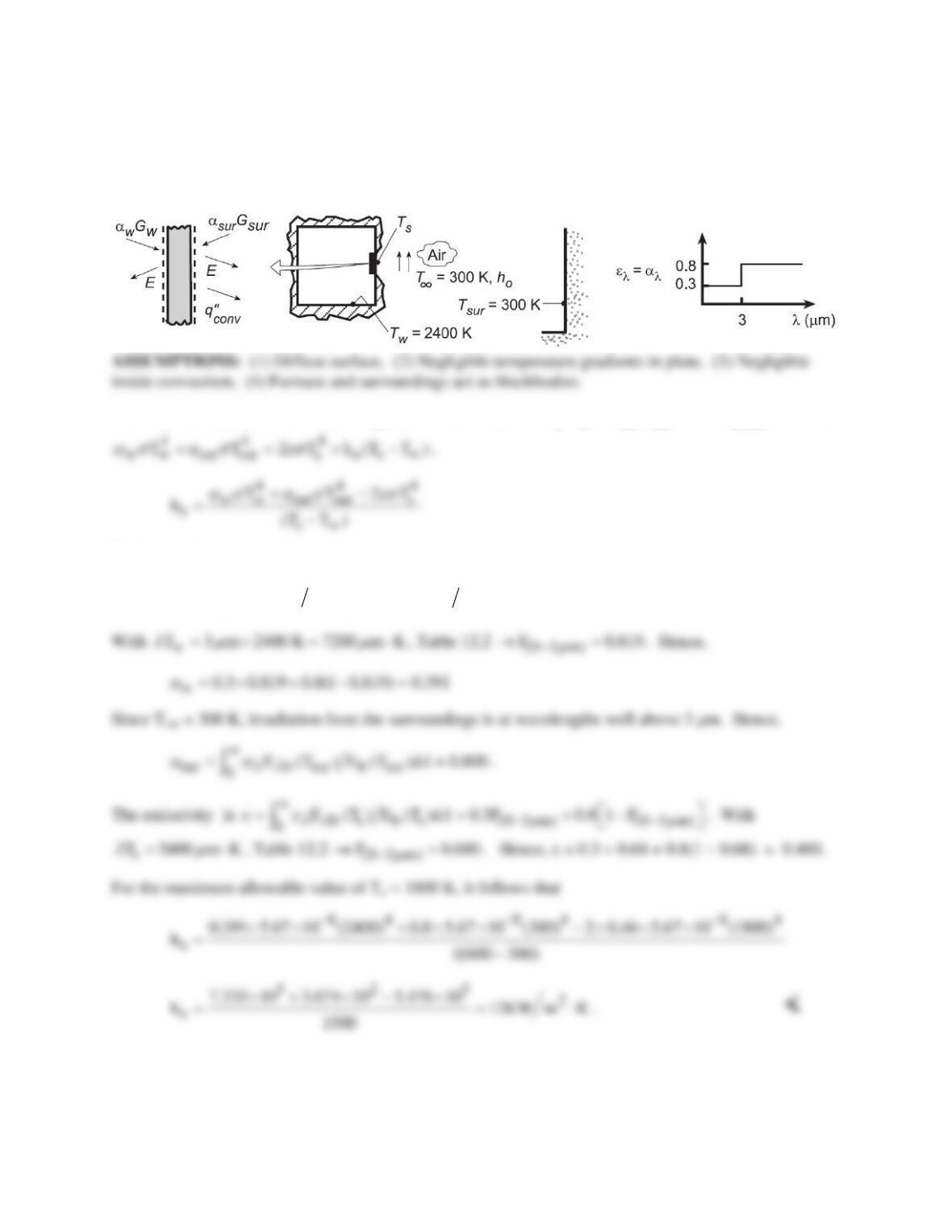
KNOWN: Temperatures of furnace and surroundings separated by ceramic plate. Maximum allowable
temperature and spectral absorptivity of plate.
FIND: (a) Minimum value of air–side convection coefficient, ho, (b) Effect of ho on plate temperature.
SCHEMATIC:
ANALYSIS: (a) From a surface energy balance on the plate,
w w sur sur conv
G G 2E q
αα
′′
+=+
. Hence,
Evaluating the absorptivities and emissivity,
w b w b w (0 3 m) (0 3 m)
00
G d G E (T ) E (T )d 0.3F 0.8 1 F
λλ λλ µ µ
α αλ α λ
∞∞ −−
= = = +−
∫∫
w
(b) Using the IHT First Law Model with the Radiation Toolpad, parametric calculations were performed
to determine the effect of ho.
Continued…
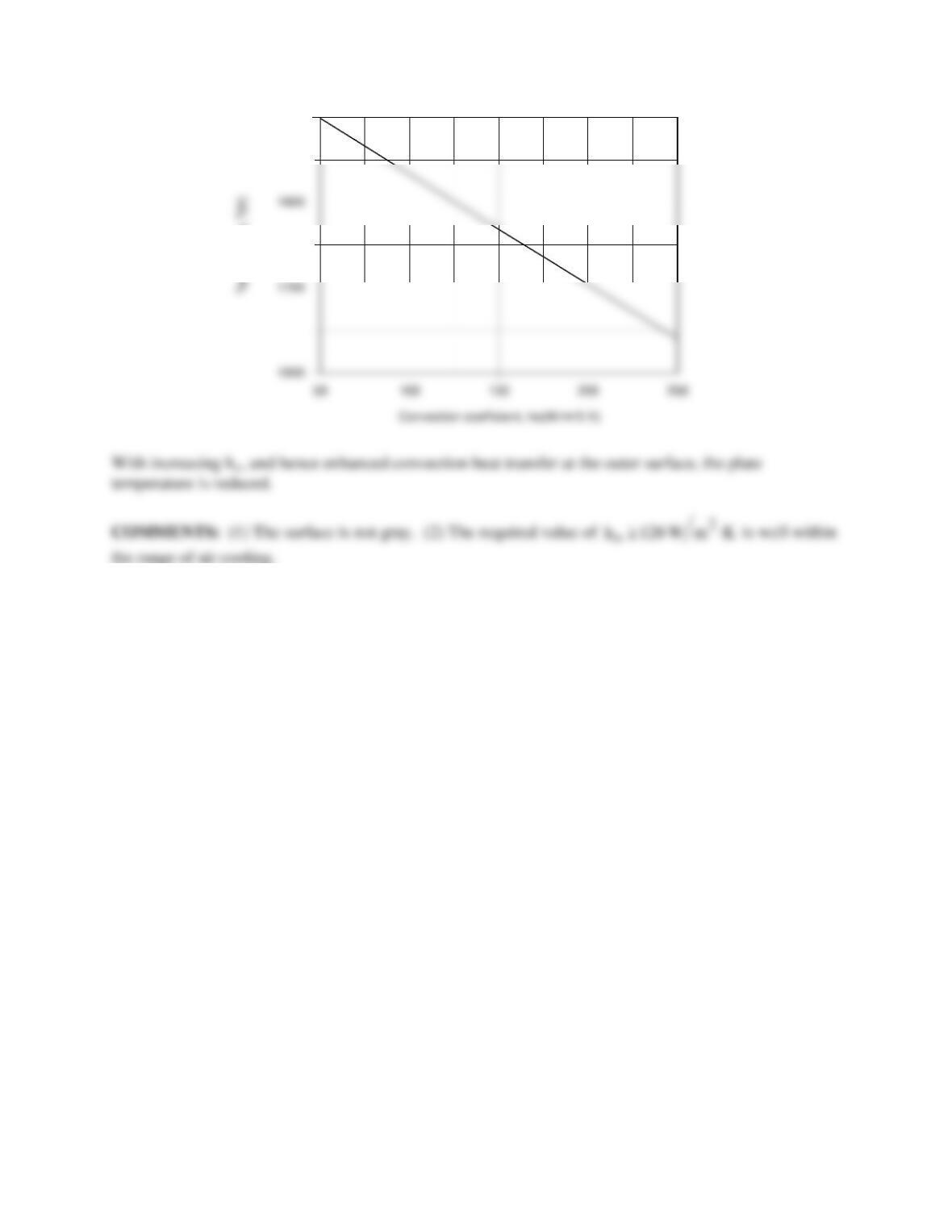
PROBLEM 12.77 (Cont.)
1900
PROBLEM 12.78
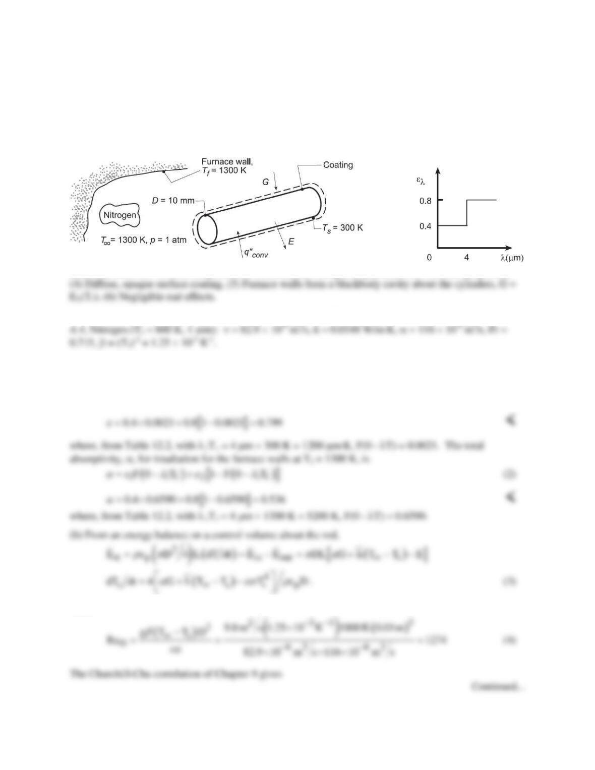
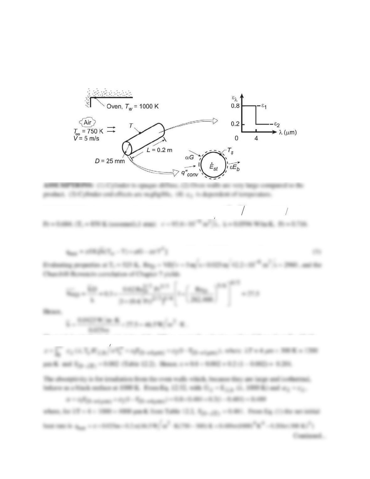
KNOWN: Spectral radiative properties of thin coating applied to long circular copper rods of prescribed
diameter and initial temperature. Wall and atmosphere conditions of furnace in which rods are inserted.
FIND: (a) Emissivity and absorptivity of the coated rods when their temperature is Ts = 300 K, (b)
Initial rate of change of their temperature, dTs/dt, (c) Emissivity and absorptivity when they reach steady–
state temperature, and (d) Time required for the rods, initially at Ts = 300 K, to reach 1000 K.
SCHEMATIC:
ASSUMPTIONS: (1) Rod temperature is uniform, (2) Nitrogen is quiescent, (3) Constant properties,
PROPERTIES: Table A.1, Copper (300 K): r = 8933 kg/m3, cp = 385 J/kg⋅K, k = 401 W/m⋅K; Table
ANALYSIS: (a) The total emissivity of the copper rod, ε, at Ts = 300 K follows from Eq. 12.43 which
can be expressed in terms of the band emission factor, F(0 – λT), Eq. 12.34,
( ) ( )
[ ]
1 1s 2 1s
F0 T 1 F0 T
εε λ ε λ
= − + −−
(1)
With
PROBLEM 12.78 (Cont.)
With values of ε and α from part (a), the rate of temperature change with time is
(c) Under steady–state conditions, Ts =
T
∞
= Tf = 1300 K. For this situation, ε = α, hence
COMMENTS: (1) To determine the validity of the lumped capacitance method to this heating process,
evaluate the approximate Biot number, Bi =
hD k
= 15 W/m2⋅K × 0.010 m/401 W/m⋅K = 0.0004. Since
Bi << 0.1, the method is appropriate.
(2) The IHT workspace with the model used for part (c) is shown below.
// Lumped Capacitance Model – irradiation, emission, convection
/* Conservation of energy requirement on the control volume, CV. */
Edotin – Edotout = Edotst
Edotin = As * ( + Gabs)
G = sigma * Tf^4
/* The independent variables for this system and their assigned numerical values are */
As = pi * D * 1 // surface area, m^2
vol = pi * D^2 / 4 * 1 // vol, m^3
rho = 8933 // density, kg/m^3

PROBLEM 12.78 (Cont.)
// Radiative Properties Tool – Band Emission Fraction
FL1Tf = F_lambda_T(lambda1,Tf) // Eq 12.34
// Assigned Variables:
D = 0.010 // Cylinder diameter, m
lambda1 = 4 // Wavelength, mum
// Correlations Tool – Free Convection, Cylinder, Horizontal:
NuDbar = NuD_bar_FC_HC(RaD,Pr) // Eq 9.34
// Properties Tool – Nitrogen: Lookup Table Function “nitrog”
nu = lookupval (nitrog, 1, Tff, 2)
k = lookupval (nitrog, 1, Tff, 3)
alphan = lookupval (nitrog, 1, Tff, 4)
Pr = lookupval (nitrog, 1, Tff, 5)
beta = 1 / Tff
/* Lookup table function, nitrog; from Table A.4 1 atm):
Columns: T(K), nu(m^2/s), k(W/m.K), alpha(m^2/s), Pr
300 1.586E-5 0.0259 2.21E-5 0.716
400 2.616E-5 0.0327 3.71E-5 0.704
500 3.824E-5 0.0389 5.47E-5 0.7
600 5.179E-5 0.0446 7.39E-5 0.701
800 8.29E-5 0.0548 0.000116 0.715
1000 0.0001187 0.0647 0.000165 0.721 */
PROBLEM 12.79
KNOWN: Large combination convection-radiation oven heating a cylindrical product of a prescribed
spectral emissivity.
FIND: (a) Initial heat transfer rate to the product when first placed in oven at 300 K, (b) Steady-state
temperature of the product, (c) Time to achieve a temperature within 50oC of the steady–state
temperature.
SCHEMATIC:
PROPERTIES: Table A-4, Air (Tf = 525 K,1 atm):
62
42.2 10 m s, k 0.0423 W m K
ν
−
=×=⋅
,
ANALYSIS: (a) The net heat rate to the product is
net s conv b
q A (q G E )
αε
′′
= +−
, or
The total, hemispherical emissivity of the diffuse, spectrally selective surface follows from Eq. 12.43,

PROBLEM 12.79 (Cont.)
(b) For the steady-state condition, the net heat rate will be zero, and the energy balance yields,
4
0 h (T T) G T
α εs
∞
= −+ −
(2)
(c) Using the IHT Lumped Capacitance Model with the Correlations, Properties (for copper and air) and
PROBLEM 12.80
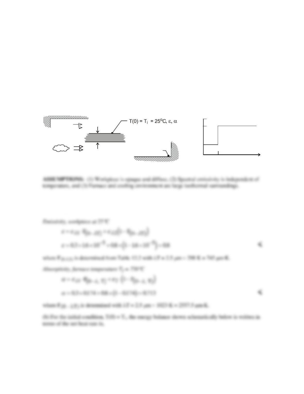
KNOWN: Workpiece, initially at 25°C, to be annealed at a temperature above 725°C for a period of
5 minutes and then cooled; furnace wall temperature and convection conditions; cooling surroundings
and convection conditions.
FIND: (a) Emissivity and absorptivity of the workpiece at 25°C when it is placed in the furnace, (b)
Net heat rate per unit area into the workpiece for this initial condition; change in temperature with
time, dT/dt, for the workpiece; (c) Calculate the time for the workpiece to cool from 750°C to a safe–
to–touch temperature of 40°C if the cool surroundings and cooling air temperature are 25°C and the
convection coefficient is 100 W/m2⋅K.
SCHEMATIC:
1.0
0.8
0.3
02.5
λ µ
( m)
ε
λ
ε
λ,1
ε
λ,2
Air L = 10 mm
Heating-annealing conditions
T = 750 C
o
o
o
h = 100 W/m -K
2
r = 2700 kg/m3
c = 885 J/kg-K
k = 165 W/m-K
T = 750 C
o
f
ANALYSIS: (a) Using Eqs. 12.43 and 12.52, ε and α can be determined using band-emission
factors, Eq. 12.34 and 12.35.
Continued …
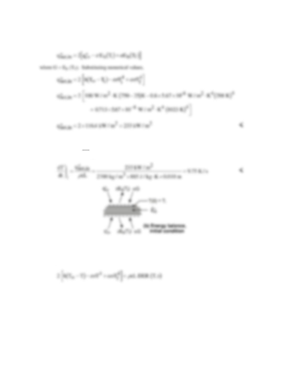
PROBLEM 12.80 (Cont.)
′′ −′′ =′′ ′′ =′′ −′′
E E E and q E E
in out st net,in in out
Considering the energy storage term,
′′ =F
H
GI
K
J=′′
EcL dT
dt q
st inet,in
r
(c) The energy balance of Part (b), using the lumped capacitance method with the IHT DER (T,t)
function, has the form,
Continued …
PROBLEM 12.80 (Cont.)
The time to cool the workpiece from 750°C to the safe–to-touch temperature of 40°C can be
determined using the IHT code in the Comments. The cooling conditions are T∞ = 25°C and h = 100
W/m2⋅K with Tsur = 25°C. The emissivity is still evaluated as in the Comments, but the absorptivity,
which depends upon the surrounding temperature, is α = 0.80. From the results in the IHT workspace,
find
T t C when t s
c c
bg= =40 413
<
COMMENTS: 1. With the relation for ε of Part (a) in the IHT workspace, and using the Radiation |
Band Emission tool, ε as a function of workpiece temperature is calculated and plotted below.
2. The IHT code to obtain the heating time, including emissivity as a function of the workpiece
temperature, Part (b), is shown below, complete except for the input variables.
/* Analysis. The radiative properties and net heat flux in are calculated when the workpiece is
Workpiece emissivity as a function of its temperature
0100 200 300 400 500 600 700 800
Temperature, T (C)
0.7
0.8
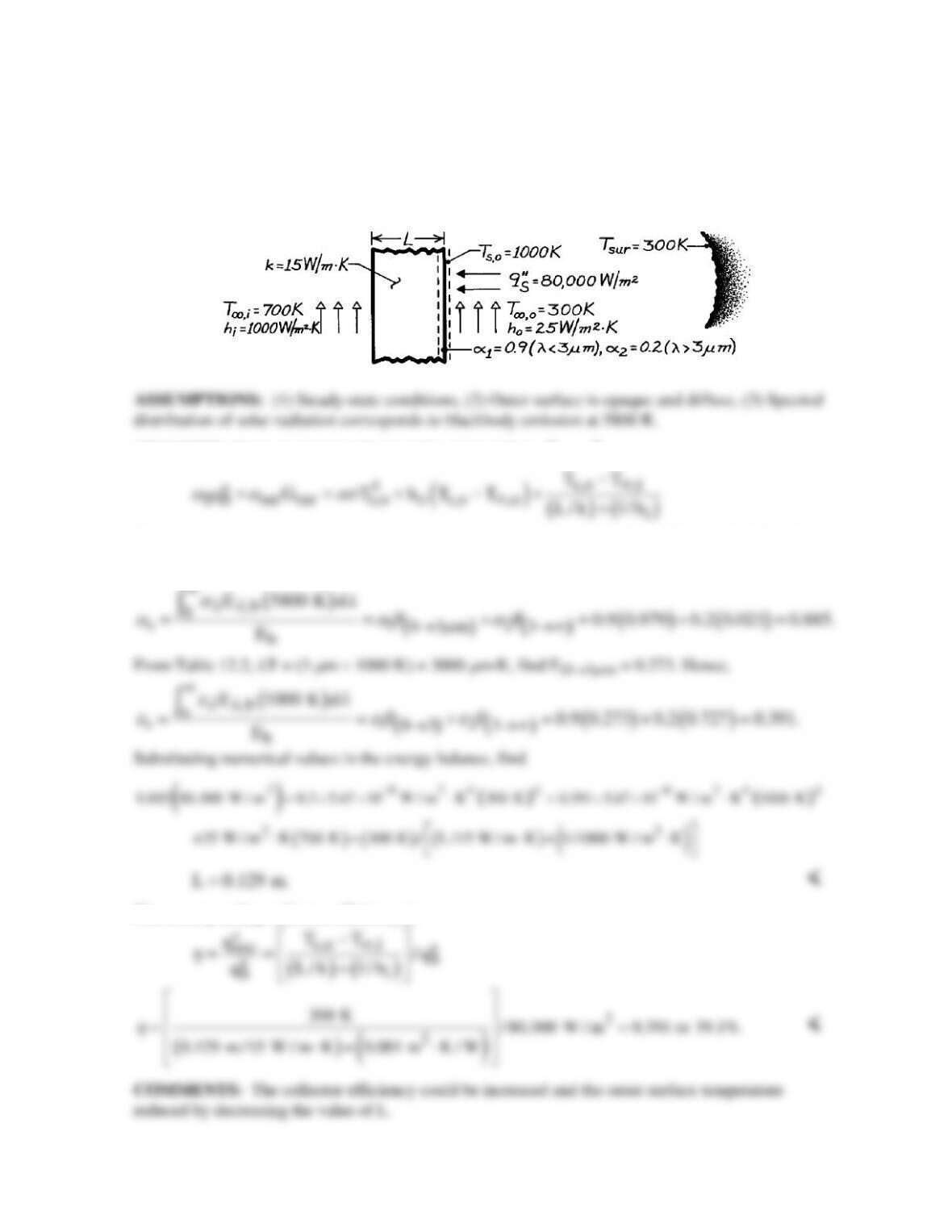
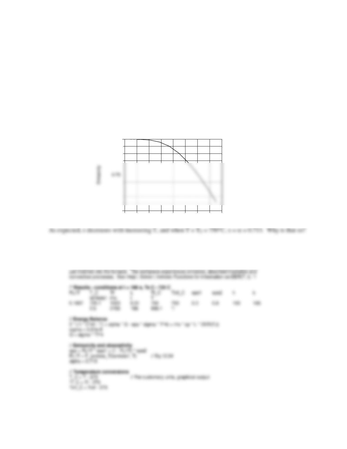
PROBLEM 12.81
KNOWN: Thermal conductivity, spectral absorptivity and inner and outer surface conditions for
wall of central solar receiver.
FIND: Minimum wall thickness needed to prevent thermal failure. Collector efficiency.
SCHEMATIC:
ANALYSIS: From an energy balance at the outer surface,
in out
E E,=
Since radiation from the surroundings is in the far infrared, αsur = 0.2. From Table 12.2, λT = (3 µm
× 5800 K) = 17,400 µm⋅K, find F(0→3µm) = 0.979. Hence,
The corresponding collector efficiency is
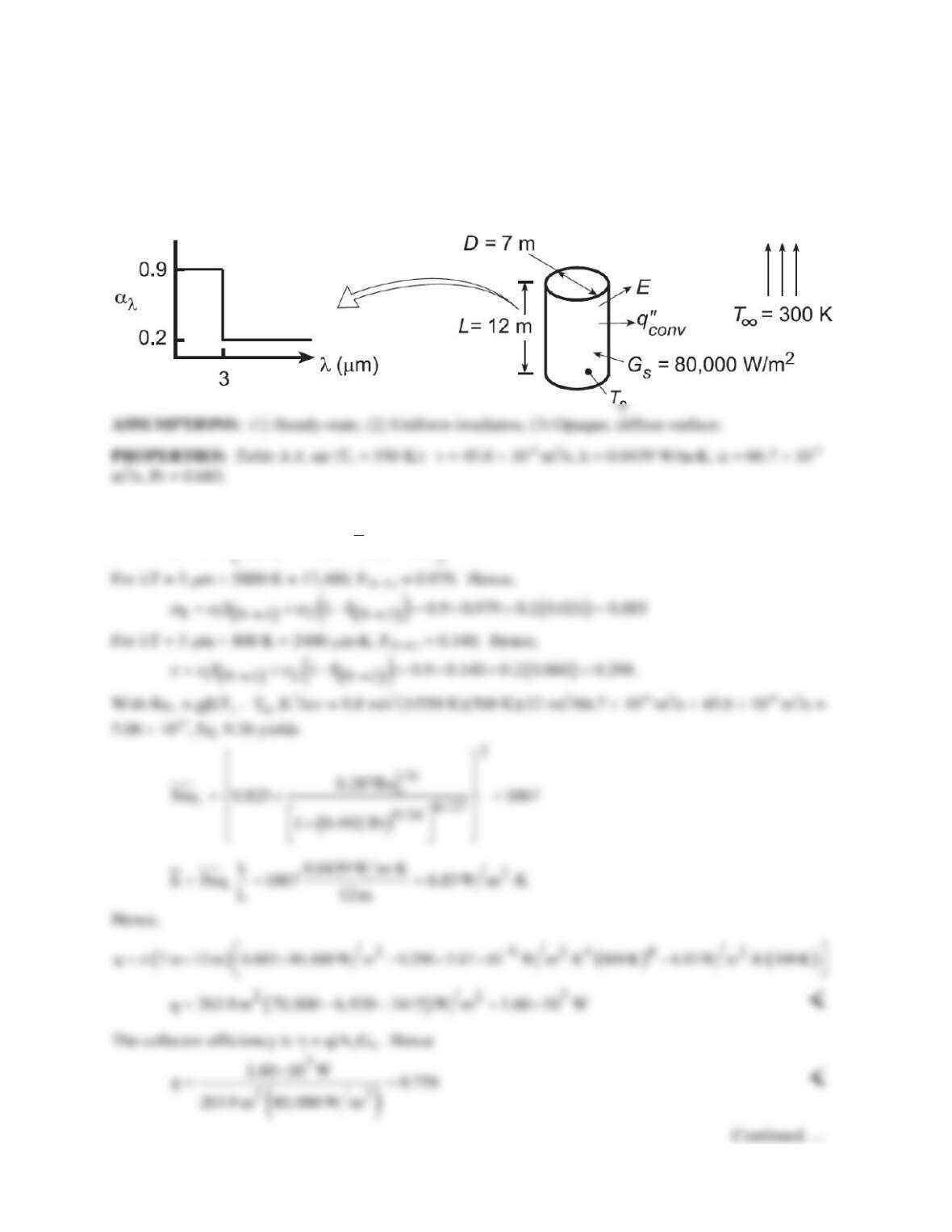
PROBLEM 12.82
KNOWN: Dimensions, spectral absorptivity, and temperature of solar receiver. Solar irradiation and
ambient temperature.
FIND: (a) Rate of energy collection q and collector efficiency η, (b) Effect of receiver temperature on q
and η.
SCHEMATIC:
ANALYSIS: (a) The rate of heat transfer to the receiver is q =
( )
s S S conv
A G Eq
α
′′
−−
, or
( )
4
SS s s
q DL G T h T T
π α εs
∞
= − −−
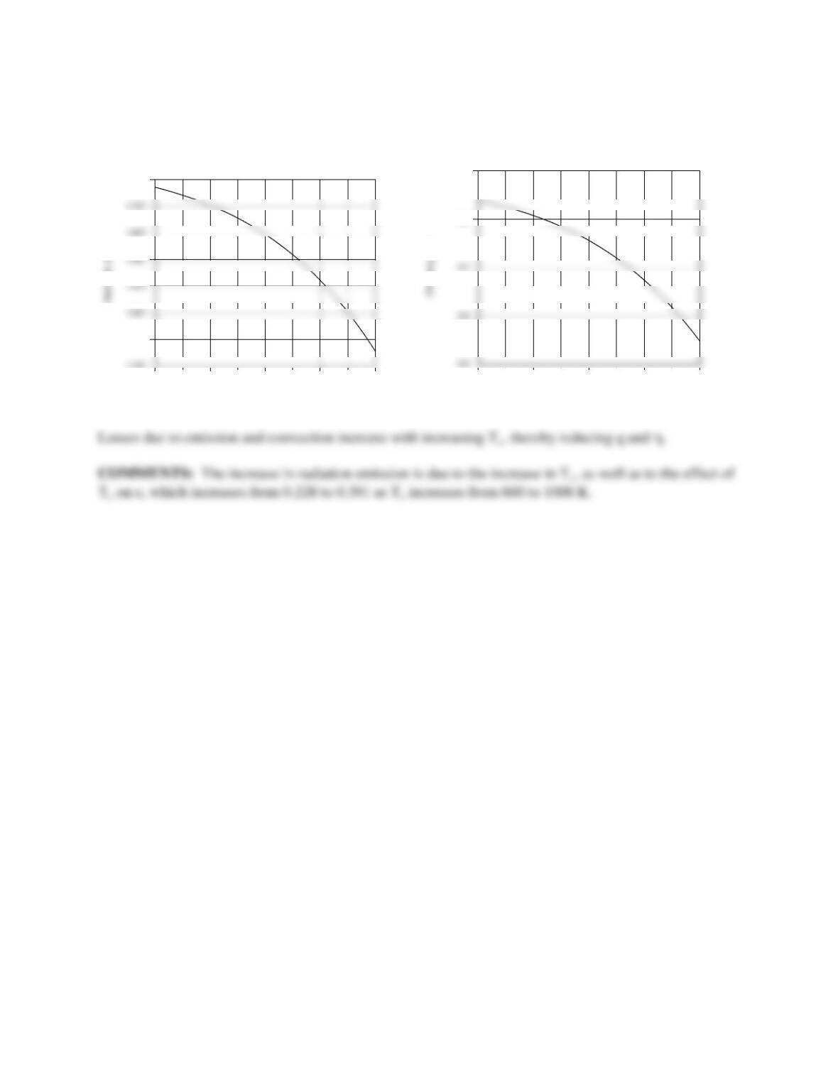
PROBLEM 12.82 (Cont.)
(b) The IHT Correlations, Properties and Radiation Toolpads were used to obtain the following results.
600 700 800 900 1000
Receiver temperature, Ts(K)
1.1E7
1.2E7
1.8E7
600 700 800 900 1000
Receiver temperature, T(K)
0.8
0.9