PROBLEM 12.1
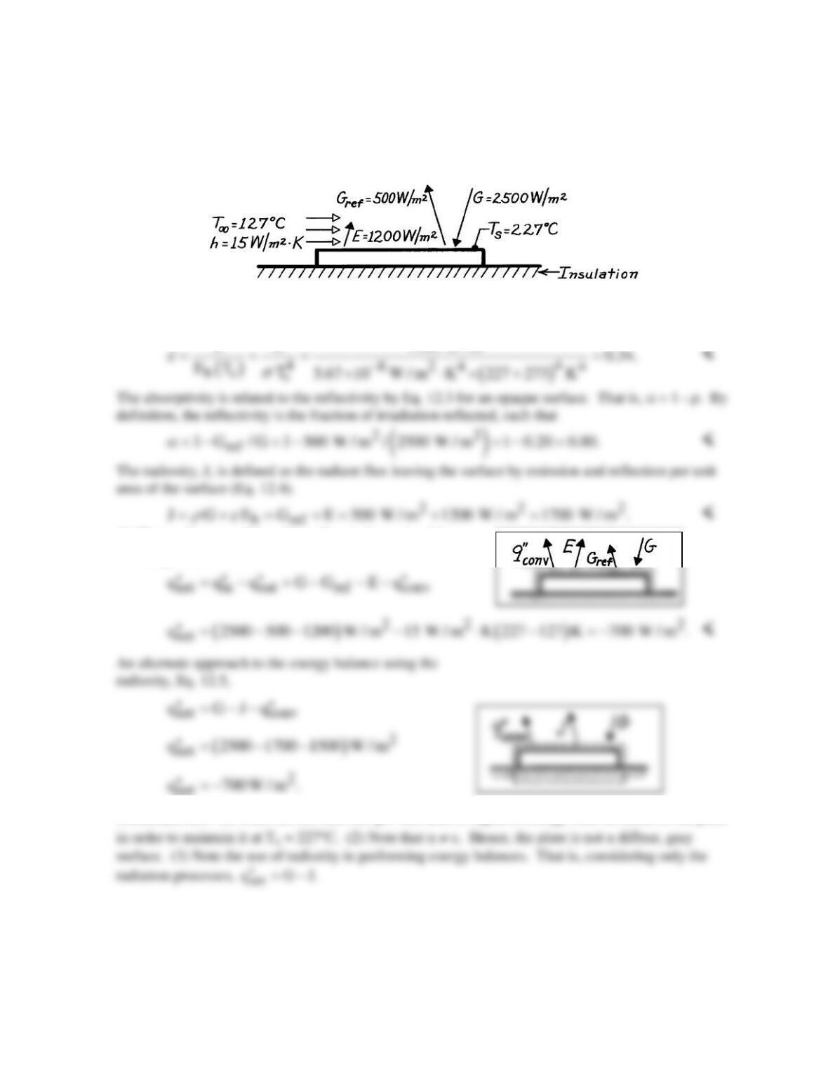
KNOWN: Opaque, horizontal plate, well insulated on backside, is subjected to a prescribed
irradiation. Also known are the reflected irradiation, emissive power, plate temperature and
convection coefficient for known air temperature.
FIND: (a) Emissivity, absorptivity and radiosity and (b) Net heat transfer per unit area of the plate.
SCHEMATIC:
ASSUMPTIONS: (1) Plate is insulated on backside, (2) Plate is opaque.
ANALYSIS: (a) The emissivity of the plate according to Table 12.1 is
2
E E 1200 W / m 0.34.
(b) The net heat transfer to the surface is determined from
an energy balance,
COMMENTS: (1) Since the net heat rate per unit area is negative, energy must be added to the plate
PROBLEM 12.2
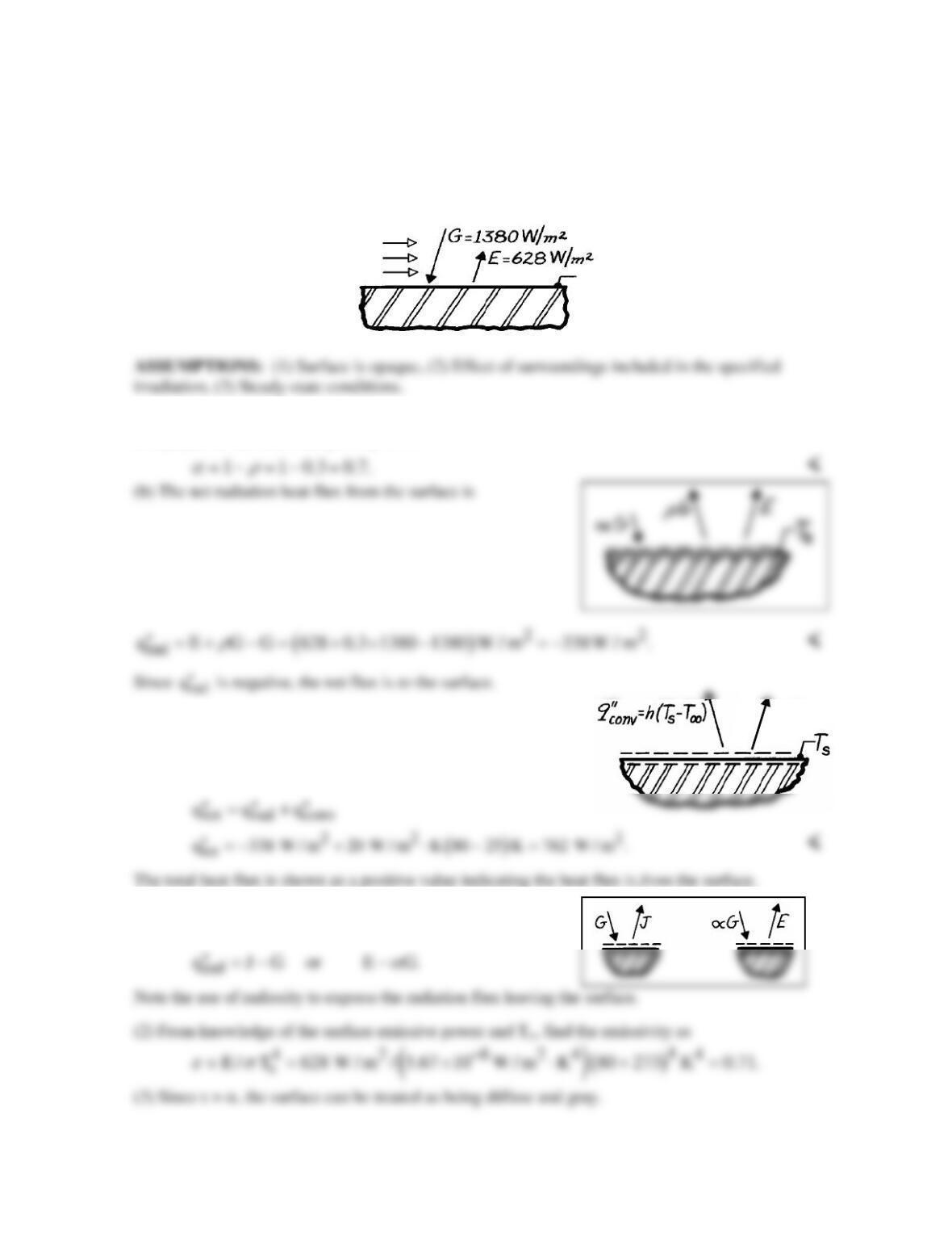
KNOWN: Horizontal, opaque surface at steady–state temperature of 80°C is exposed to a convection
process; emissive power, irradiation and reflectivity are prescribed.
FIND: (a) Absorptivity of the surface, (b) Net radiation heat flux for the surface; indicate direction,
(c) Total heat flux for the surface; indicate direction.
SCHEMATIC:
ANALYSIS: (a) From the definition of the thermal radiative properties and a radiation balance for
an opaque surface, according to Eq. 12.3,
(c) Performing a surface energy balance considering all
heat transfer processes, the local heat flux is
COMMENTS: (1) Note that the surface radiation
balance could also be expressed as
qrad
″
T
∞
= 25°C
h = 20 W/m
2
∙
KT
s
= 80°C, ρ= 0.3
PROBLEM 12.3
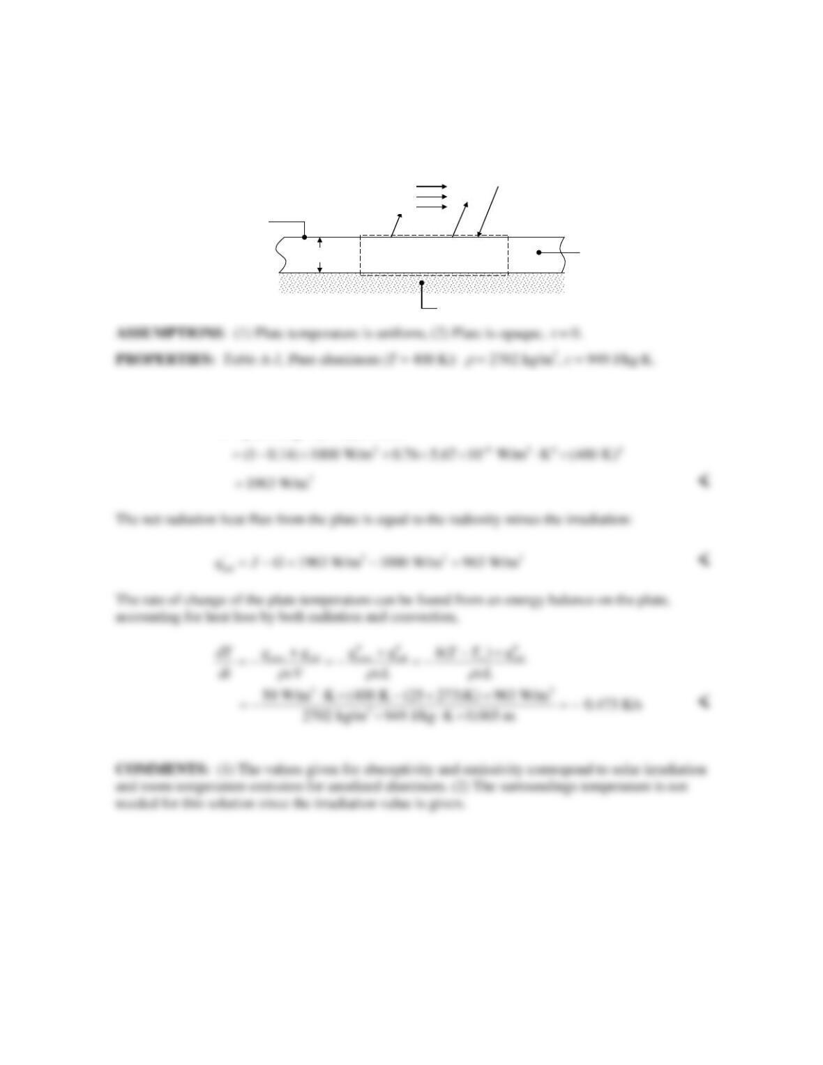
KNOWN: Thickness and temperature of aluminum plate. Irradiation. Convection conditions.
Absorptivity and emissivity.
FIND: Radiosity and net radiation heat flux at top plate surface, rate of change of plate temperature.
SCHEMATIC:
ANALYSIS: The radiosity is equal to the sum of emitted and reflected radiation:
4
(1 )
b
J GE G T
ρ ε α εσ
=+=− +
L= 5 mm
G= 1000 W/m
2
α
= 0.14
ε
= 0.76
T
∞
= 30°C
h= 40 W/m
2
∙K
Insulation
T= 400 K
J
q
conv
″
q
conv
″
T
∞
= 25°C
h= 50 W/m2∙K
PROBLEM 12.4
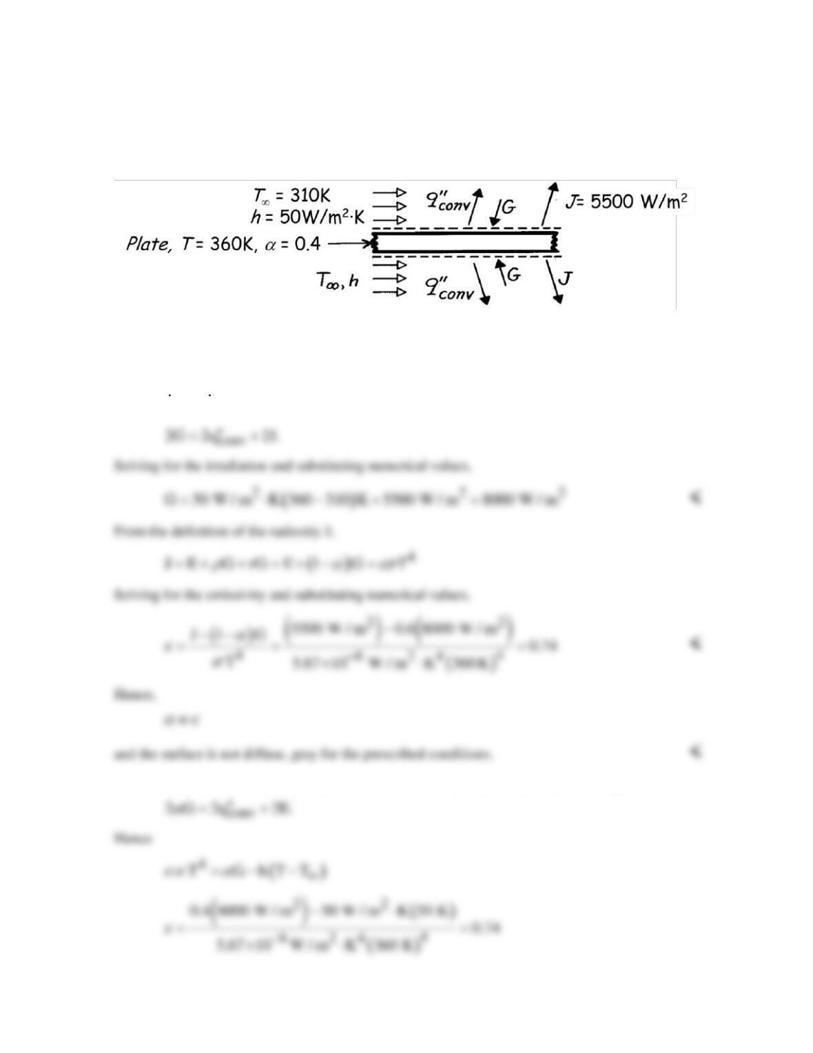
KNOWN: Temperature, absorptivity, transmissivity, radiosity and convection conditions for a
semitransparent plate.
FIND: Plate irradiation and total hemispherical emissivity.
SCHEMATIC:
ASSUMPTIONS: (1) Steady-state conditions, (2) Uniform surface conditions.
ANALYSIS: From an energy balance on the plate
in out
EE
COMMENTS: The emissivity may also be determined by expressing the plate energy balance as
PROBLEM 12.5
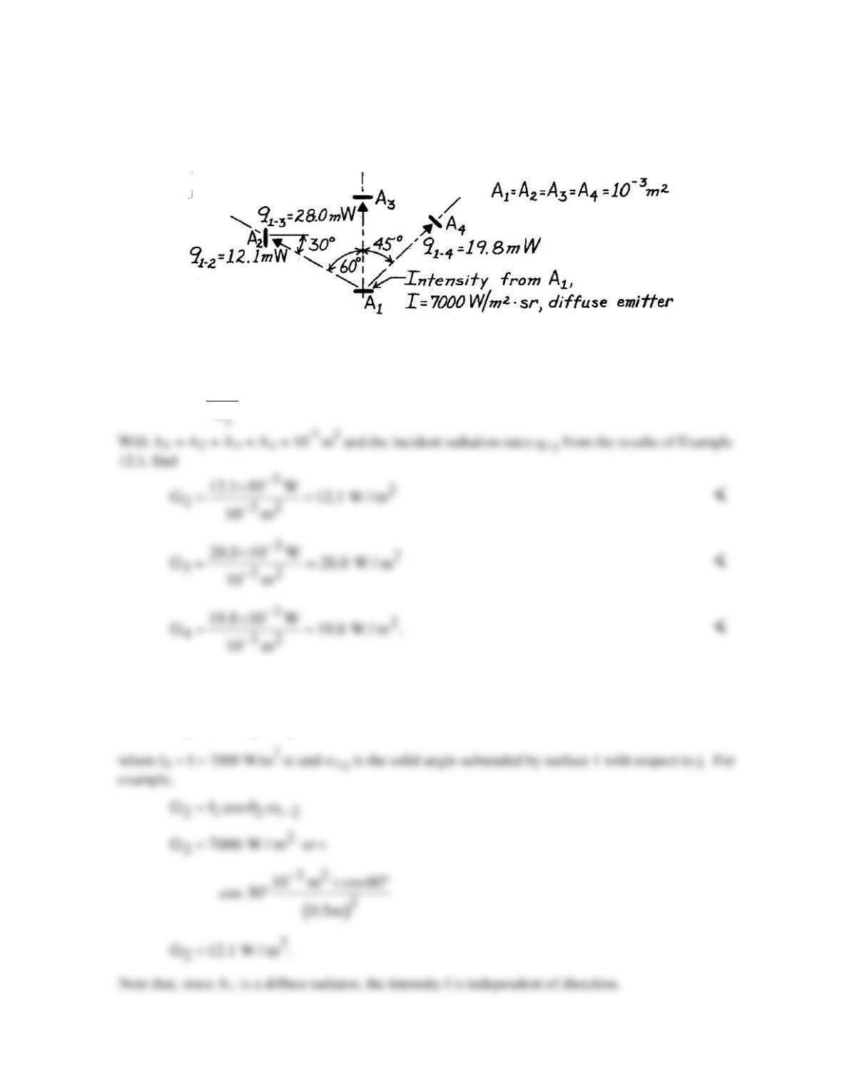
KNOWN: Rate at which radiation is intercepted by each of three surfaces (see Example 12.1).
FIND: Irradiation, G [W/m2], at each of the three surfaces.
SCHEMATIC:
ANALYSIS: The irradiation at a surface is the rate at which radiation is incident on a surface per
unit area of the surface. The irradiation at surface j due to emission from surface 1 is
1j
jj
q
G.
A
−
=
COMMENTS: The irradiation could also be computed from Eq. 12.18, which, for the present
situation, takes the form
j 1 j 1j
G I cos
θω
−
=
PROBLEM 12.6
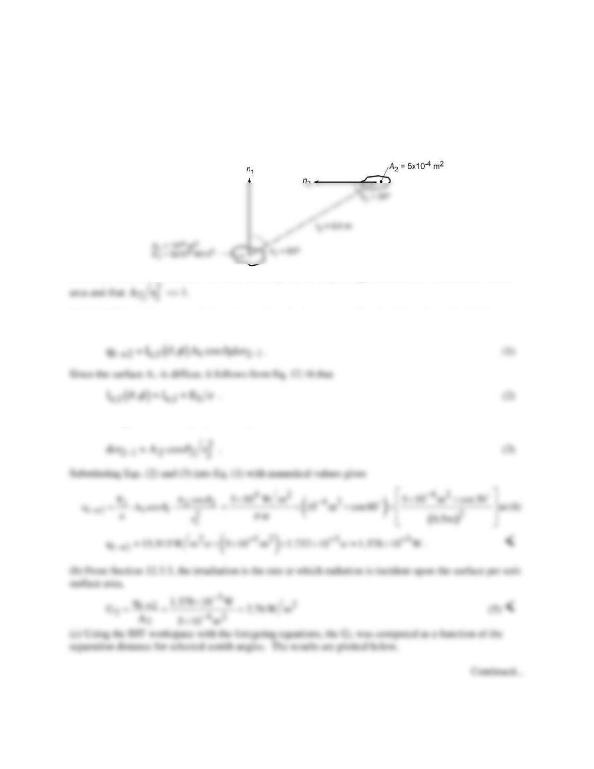
KNOWN: A diffuse surface of area A1 = 10-4m2 emits diffusely with total emissive power E = 5 × 10⁴
W/m2 .
FIND: (a) Rate this emission is intercepted by small surface of area A2 = 5 × 10⁻⁴ m2 at a prescribed
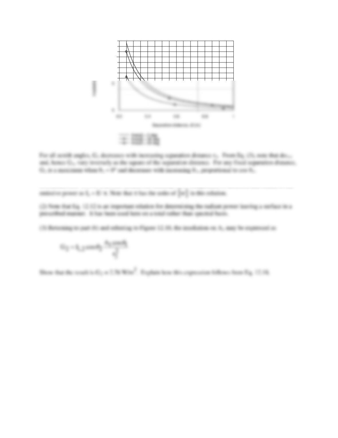
location and orientation, (b) Irradiation G2 on A2, and (c) Compute and plot G2 as a function of the
separation distance r2 for the range 0.25 ≤ r2 ≤ 1.0 m for zenith angles θ2 = 0, 30 and 60°.
SCHEMATIC:
ASSUMPTIONS: (1) Surface A1 emits diffusely, (2) A1 may be approximated as a differential surface
ANALYSIS: (a) The rate at which emission from A1 is intercepted by A2 follows from Eq. 12.11 written
on a total rather than spectral basis.
The solid angle subtended by A2 with respect to A1 is
PROBLEM 12.6 (Cont.)
10
COMMENTS: (1) For a diffuse surface, the intensity, Ie, is independent of direction and related to the
PROBLEM 12.7
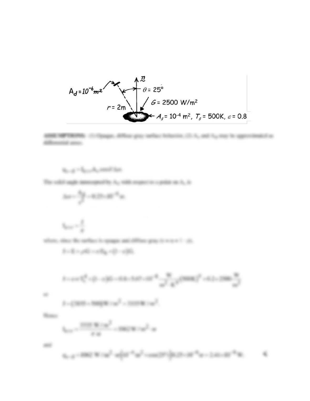
KNOWN: Irradiation and temperature of a small surface.
FIND: Rate at which radiation is received by a detector due to emission and reflection from the
surface.
SCHEMATIC:
ANALYSIS: Radiation intercepted by the detector is due to emission and reflection from the surface,
and from the definition of the intensity, it may be expressed as
Since the surface is diffuse it follows from Eq. 12.27 that
Substituting for Eb from Eq. 12.32
PROBLEM 12.8
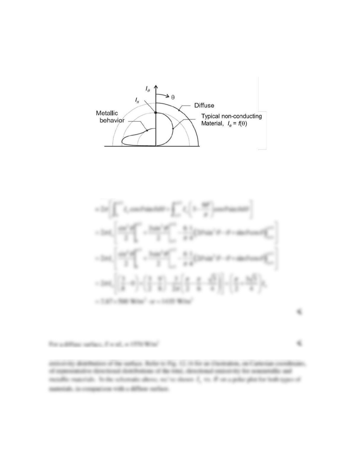
KNOWN: Emitted intensity distribution of a non-conducting material.
FIND: Total emissive power of the surface and compare the value to that of a diffuse surface of
intensity In.
SCHEMATIC:
ANALYSIS: From Eq. 12.15, written on a total rather than spectral basis, the emissive power is
2 /2
00
( , )cos sin
e
E I dd
pp
θφ θ θ θ φ
=
∫∫
COMMENTS: From Equation 12.38, the emitted intensity distribution is related to the directional
PROBLEM 12.9
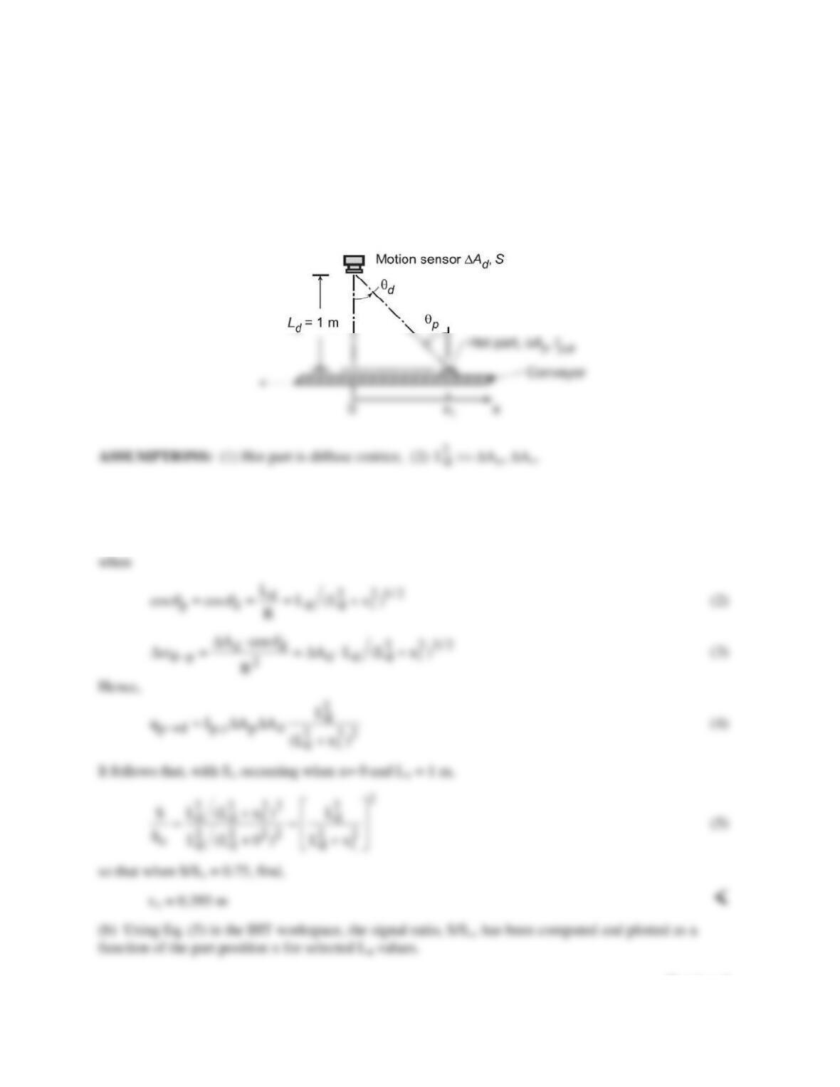
KNOWN: Hot part, ∆Ap, located a distance x1 from an origin directly beneath a motion sensor at a
distance Ld = 1 m.
FIND: (a) Location x1 at which sensor signal S1 will be 75% that corresponding to x = 0, directly
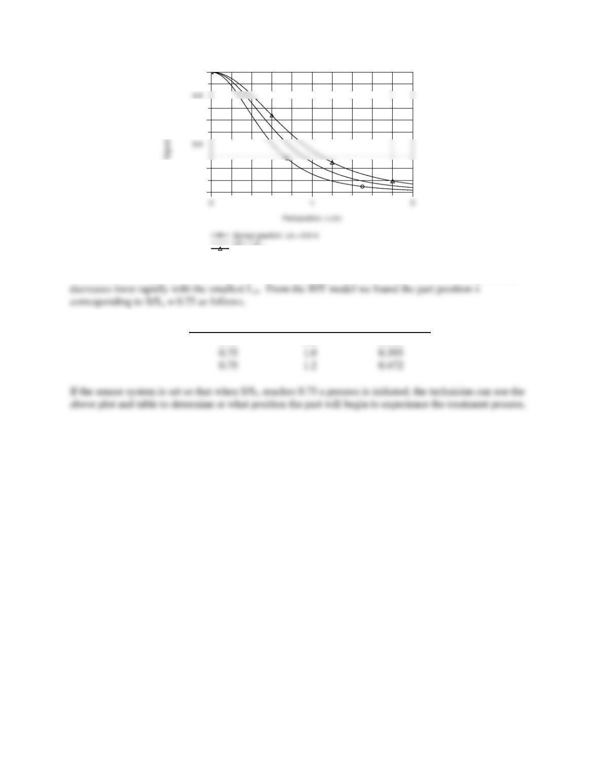
beneath the sensor, So, and (b) Compute and plot the signal ratio, S/So, as a function of the part position
x1 for the range 0.2 ≤ S/So ≤ 1 for Ld = 0.8, 1.0 and 1.2 m; compare the x-location for each value of Ld at
which S/So = 0.75.
SCHEMATIC:
ANALYSIS: (a) The sensor signal, S, is proportional to the radiant power leaving ∆Ap and intercepted
by ∆Ad,
p d p,e p p d p
S ~ q I A cos
θω
→−
=∆∆
(1)
Continued…
PROBLEM 12.9 (Cont.)
0
0.2
0.6
1
Ld = 1.2 m
When the part is directly under the sensor, x = 0, S/So = 1 for all values of Ld. With increasing x, S/So
S/So
Ld (m)
x1 (m)
0.75
0.8
0.315
0.75
1.0
0.393
0.75
1.2
0.472
PROBLEM 12.10
KNOWN: Surface area, and emission from area A1. Size and orientation of area A2.
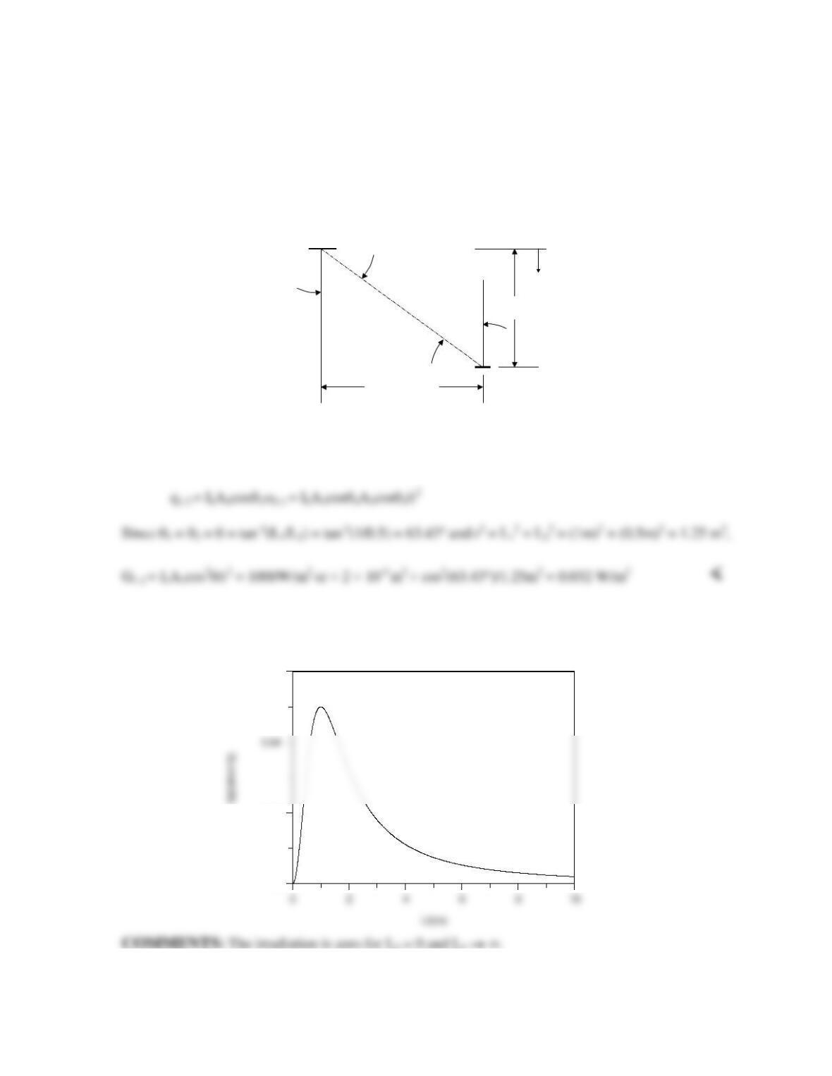
FIND: (a) Irradiation of A2 by A1 for L1 = 1 m, L2 = 0.5 m, (b) Irradiation of A2 over the range 0
≤ L2 ≤ 10 m.
SCHEMATIC:
ASSUMPTIONS: Diffuse emission.
ANALYSIS: (a) The irradiation of Surface 1 is G1-2 = q1-2/A2 and from Example 12.1,
(b) The preceding equations may be solved for various values of L2. The irradiation over
the range 0 ≤ L2 ≤ 10 m is shown below.
Irradiation of Surface 2 vs. Distance L2
0
0.02
0.06
x
L
2
= 0.5 m
L
1
= 1 m
A
1
A
2
I
1
= 1000 W/m
2
·sr
θ
1
θ
2
x
L
2
= 0.5 m
L
1
= 1 m
A
1
A
2
I
1
= 1000 W/m
2
·sr
θ
1
θ
2
PROBLEM 12.11
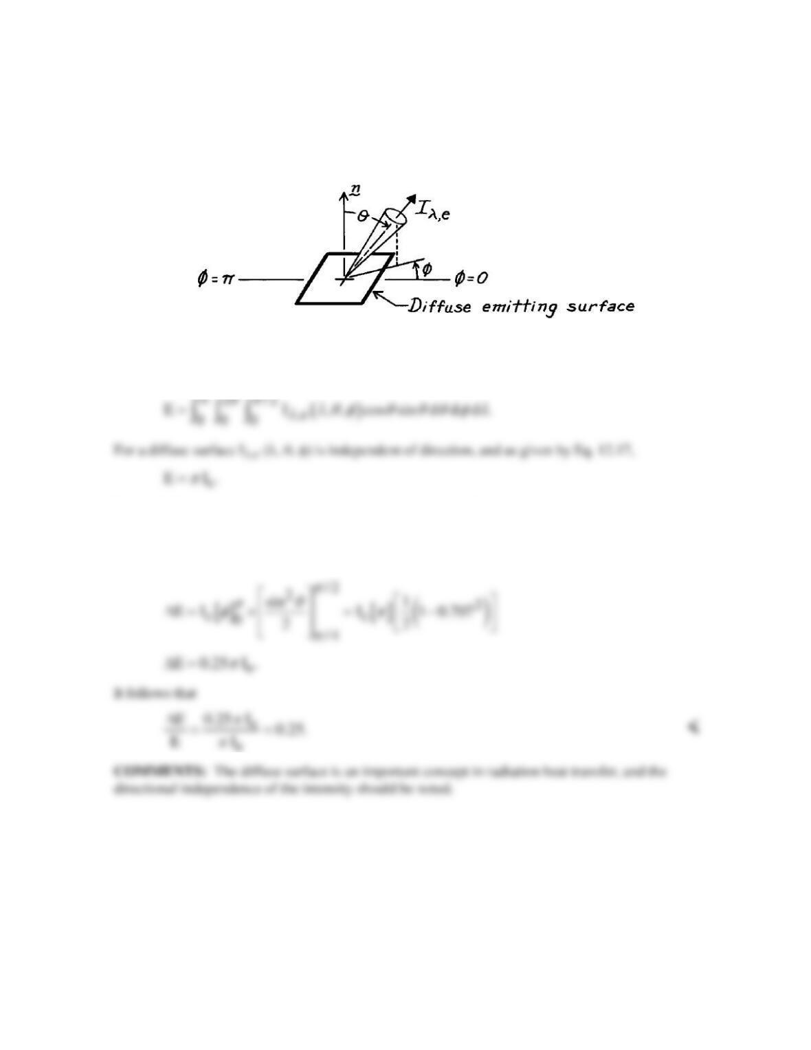
KNOWN: Emissive power of a diffuse surface.
FIND: Fraction of emissive power that leaves surface in the directions p/4 ≤ θ ≤ p/2 and 0 ≤ φ ≤ p.
SCHEMATIC:
ASSUMPTIONS: (1) Diffuse emitting surface.
ANALYSIS: According to Eq. 12.15, the total, hemispherical emissive power is
The emissive power, which has directions prescribed by the limits on θ and φ, is
( )
/2
,e
0 0 /4
E I d d cos sin d
pp
λp
λ λ φ θ θθ
∞
∆=
∫ ∫∫
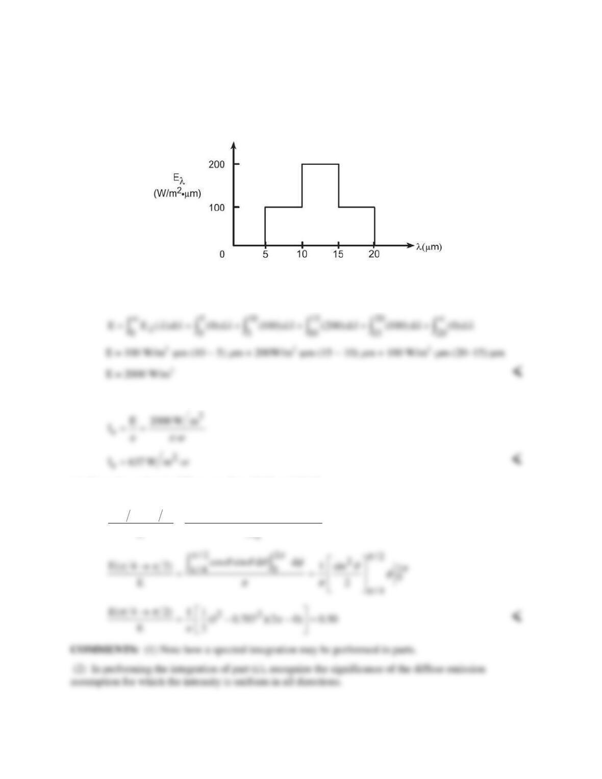
PROBLEM 12.12
KNOWN: Spectral distribution of Eλ for a diffuse surface.
FIND: (a) Total emissive power E, (b) Total intensity associated with directions θ = 0o and θ = 30o,
and (c) Fraction of emissive power leaving the surface in directions p/4 ≤ θ ≤ p/2.
SCHEMATIC:
ASSUMPTIONS: (1) Diffuse emission.
ANALYSIS: (a) From Eq. 12.14 it follows that
(b) For a diffuse emitter, Ie is independent of θ and Eq. 12.17 gives
(c) Since the surface is diffuse, use Eqs. 12.13 and 12.17,
2 /2
e
0 /4
I cos sin d d
E( 4 2)
EI
pp
p
θ θθφ
pp
p
→=∫∫
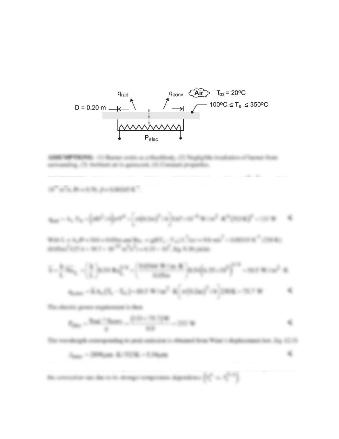
PROBLEM 12.13
KNOWN: Diameter and temperature of burner. Temperature of ambient air. Burner efficiency.
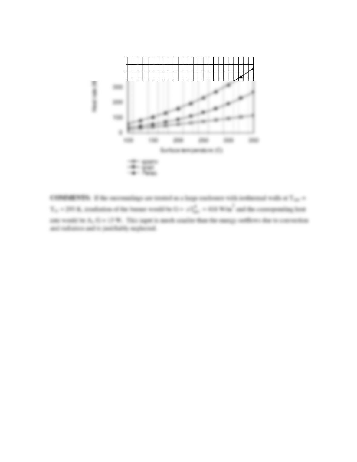
FIND: (a) Radiation and convection heat rates, and wavelength corresponding to maximum spectral
emission. Rate of electric energy consumption. (b) Effect of burner temperature on convection and
radiation rates.
SCHEMATIC:
PROPERTIES: Table A-4, air (Tf = 408 K): k = 0.0344 W/m⋅K,
ν
= 27.4 × 10⁻⁶ m2/s,
α
= 39.7 ×
ANALYSIS: (a) For emission from a blackbody
(b) As shown below, and as expected, the radiation rate increases more rapidly with temperature than
Continued …
PROBLEM 12.13 (Cont.)
400
500
PROBLEM 12.14
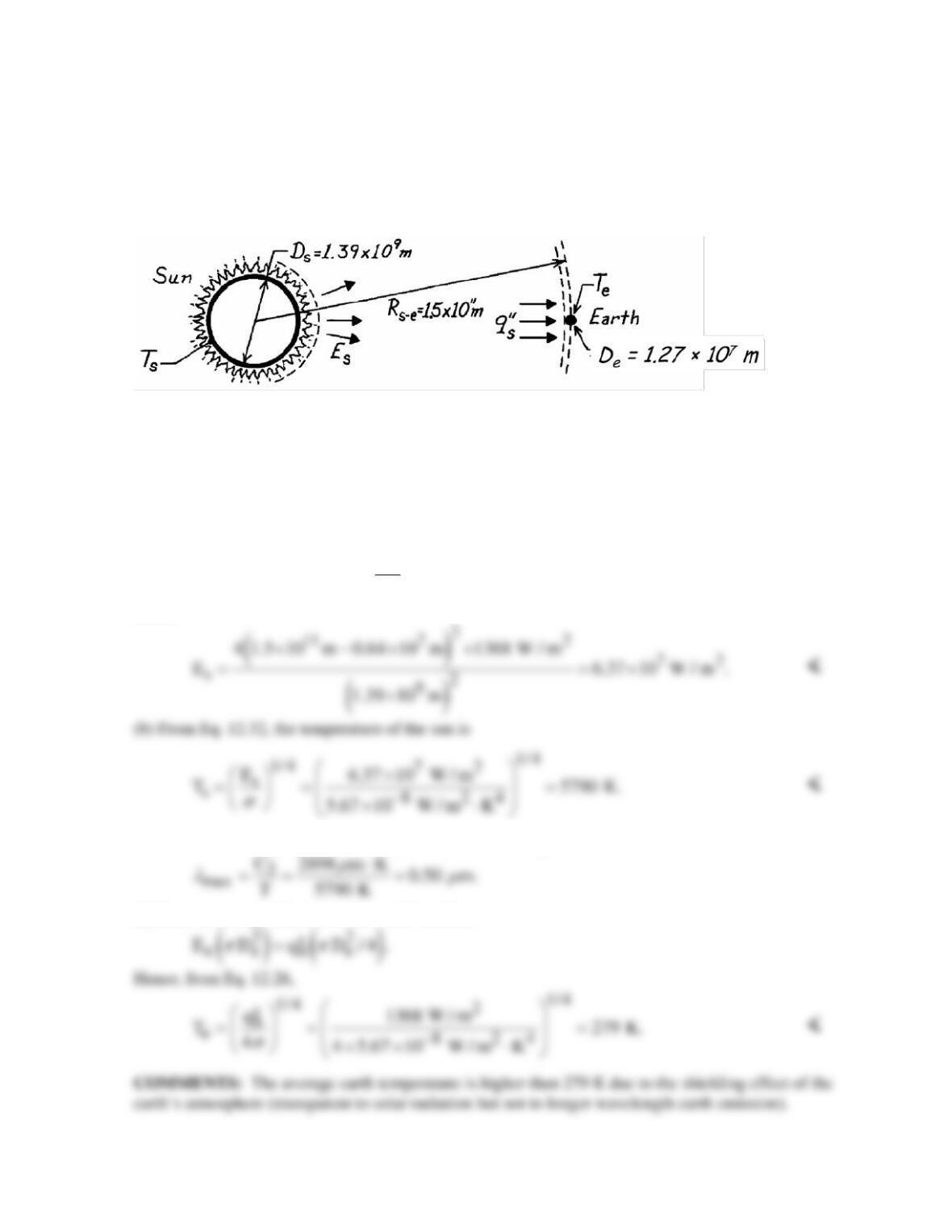
KNOWN: Solar flux at outer edge of earth’s atmosphere, 1368 W/m2.
FIND: (a) Emissive power of sun, (b) Surface temperature of sun, (c) Wavelength of maximum solar
emission, (d) Earth equilibrium temperature.
SCHEMATIC:
ASSUMPTIONS: (1) Sun and earth emit as blackbodies, (2) No attenuation of solar radiation
enroute to earth, (3) Earth atmosphere has no effect on earth energy balance.
ANALYSIS: (a) Applying conservation of energy to the solar energy crossing two concentric
spheres, one having the radius of the sun and the other having the radial distance from the edge of the
earth’s atmosphere to the center of the sun
()
2
2e
s s se
D
E D 4 R q s.
2
pp
−
′′
= −
Hence
(c) From Wien’s displacement law, Eq. 12.25, the wavelength of maximum emission is
(d) From an energy balance on the earth’s surface
PROBLEM 12.15
KNOWN: Evacuated, aluminum sphere (D = 2m) serving as a radiation test chamber.
FIND: Irradiation on a small test object when the inner surface is lined with carbon black and at
800K. What effect will surface coating have?
( )
1
G 5.67 10 W / m K 800K 23,220 W / m .
=×⋅=
<
The irradiation is independent of the nature of the enclosure surface coating properties.
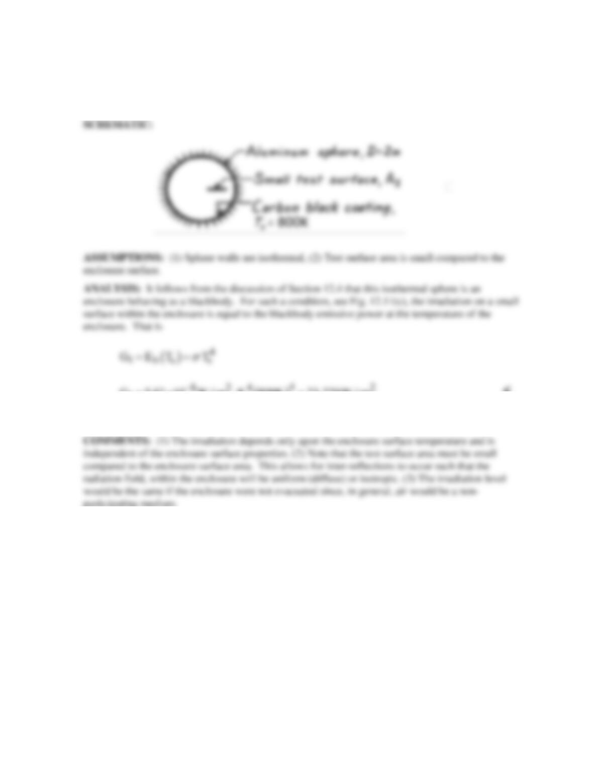
PROBLEM 12.16
KNOWN: Diameter of spherical fuel pellet. Pellet emissivity and absorptivity. Laser power and
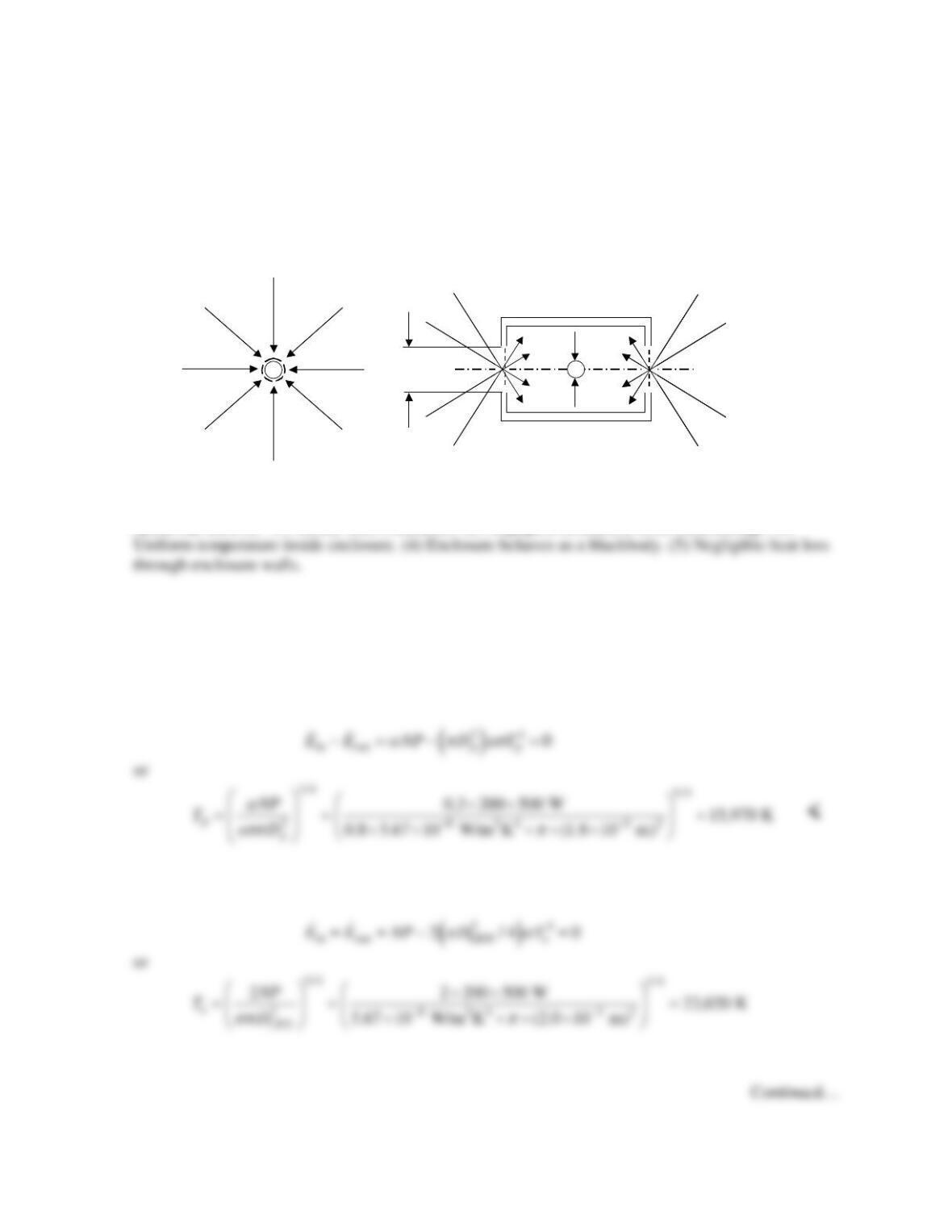
number of lasers. Laser entrance hole diameters.
FIND: (a) Maximum fuel temperature for direct laser irradiation. (b) Maximum fuel temperature for
irradiation using the enclosure.
SCHEMATIC:
ASSUMPTIONS: (1) Steady state conditions. (2) Negligible irradiation from surroundings. (3)
PROPERTIES: Given:
ε
= 0.8,
α
= 0.3.
ANALYSIS:
(a) An energy balance on the spherical pellet yields
(b) An energy balance on the enclosure yields
(a) (b)
N= 200 laser beams
P= 50 W
N= 200 laser beams
P= 50 W
D
p
= 1.8 mm D
p
(a) (b)
N= 200 laser beams
P= 50 W
N= 200 laser beams
P= 50 W
D
p
= 1.8 mm D
p
D
LEH
= 2 mm
PROBLEM 12.16 (Cont.)
COMMENTS: (1) The temperature of the pellet is increased by 44% by placing it in the enclosure.
(2) The actual maximum temperature of the pellet in the enclosure can be much less than calculated if
the area of the laser entrance holes is not small relative to the interior area of the enclosure. (3) The