An Introduction to Shear Strength Chapter 12
CHAPTER 12
AN INTRODUCTION TO SHEAR STRENGTH OF SOILS
AND ROCK
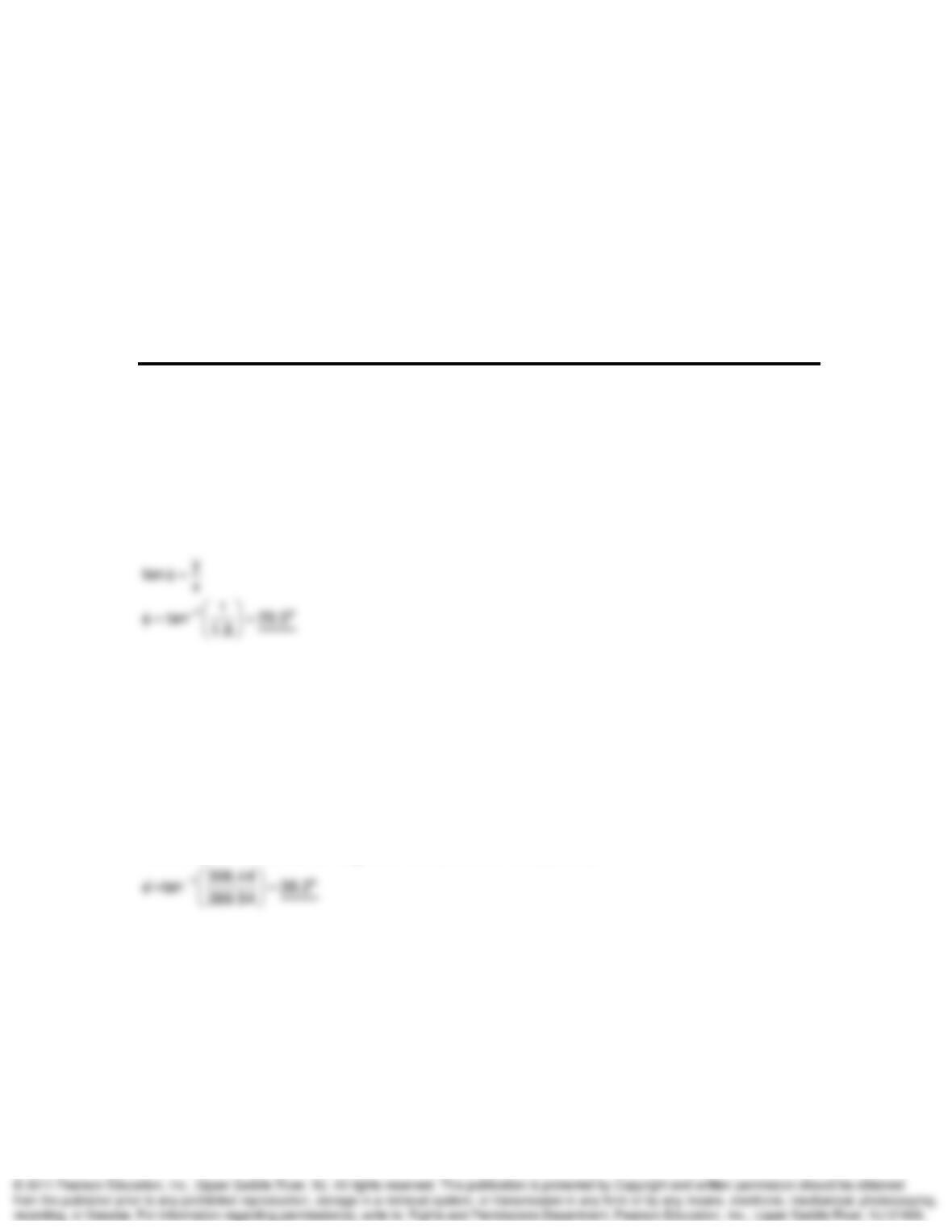
12-1. A granular material is observed being dumped from a conveyor belt. It forms a conical pile
with about the same slope angle, 1.8 horizontal to 1 vertical. What is the angle of internal friction
of this material?
SOLUTION:
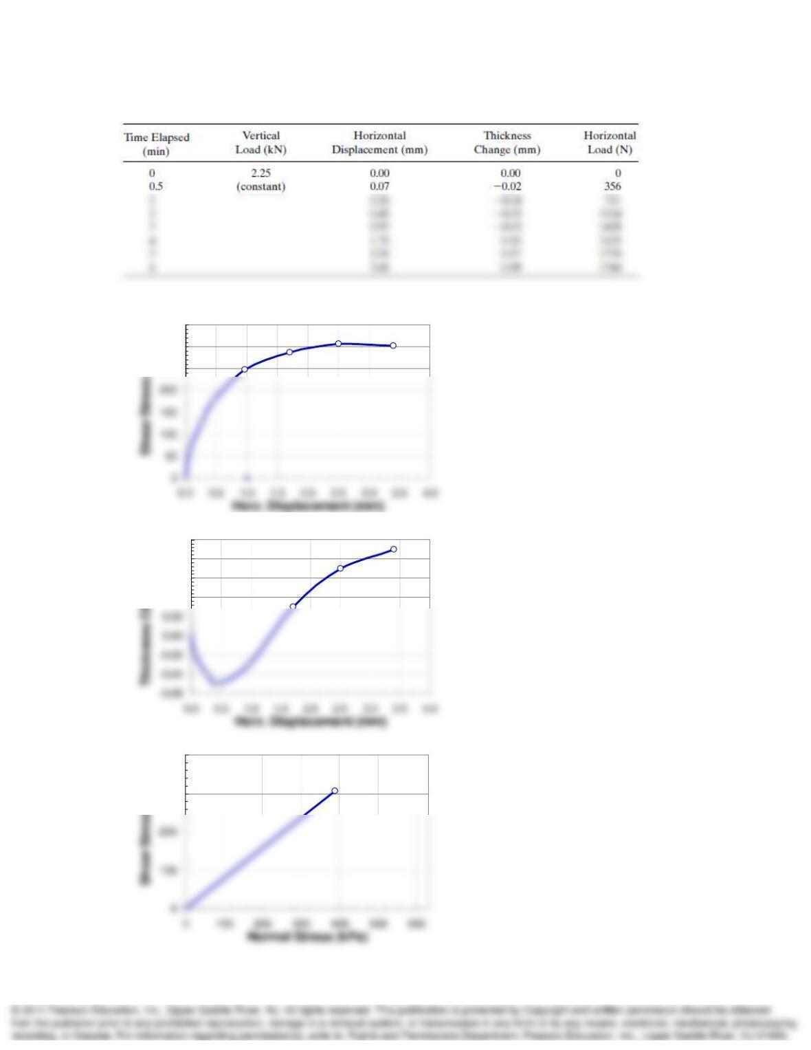
12-4. A direct shear test was conducted on a fairly dense sample of Franklin Falls sand from
New Hampshire. The initial void ratio was 0.668. The shear box was 76 mm square, and initially
the height of the specimen was 11 mm. The tabulated data were collected during shear. Compute
the data needed and plot the usual curves for this type of test.
SOLUTION:
Assuming c = 0, the friction angle can be calculated from plot 3 as:
continued on next page.
An Introduction to Shear Strength Chapter 12
12-4 data table.
250
300
350
)
0.04
0.06
0.08
0.10
m
300
400
)
An Introduction to Shear Strength Chapter 12
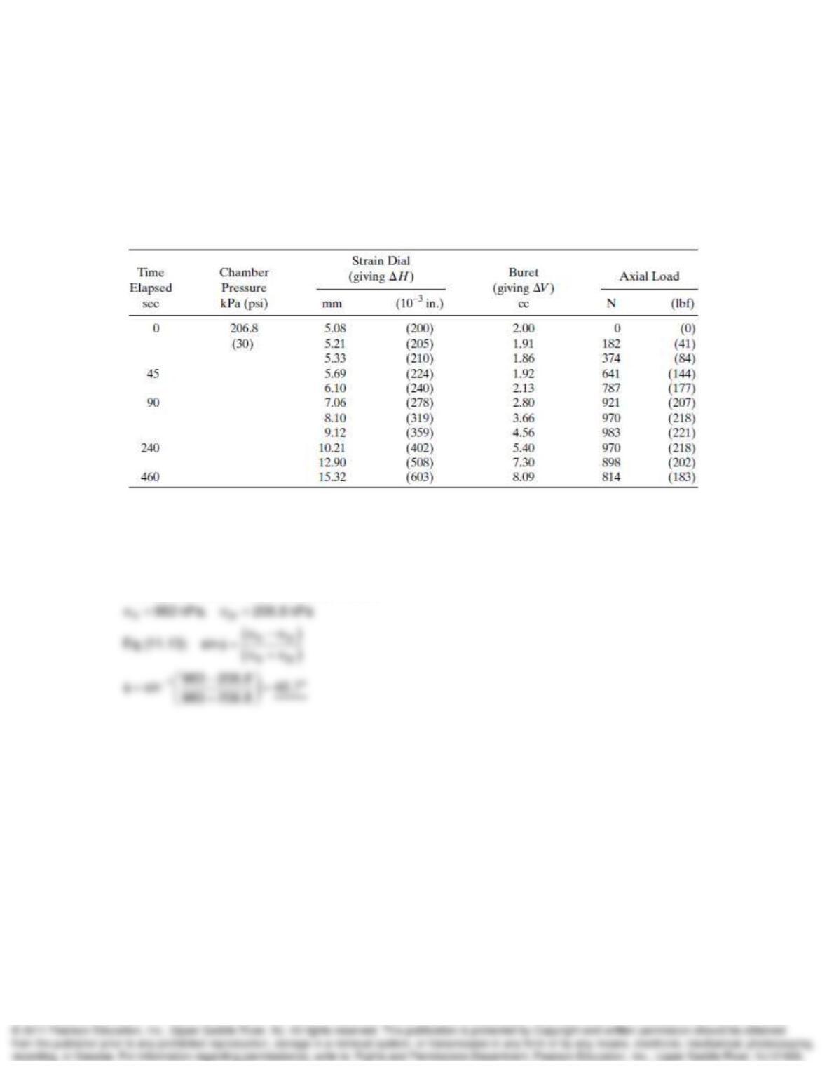
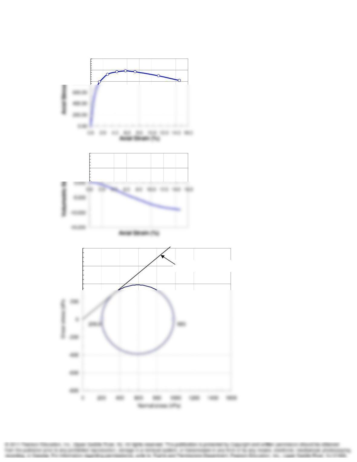
12-5. A conventional triaxial compression test was conducted on a sample of dense sand from
Ft. Peck Dam, Montana. The initial area of the test specimen was 10 cm2 and its initial height
was 70 mm. Initial void ratio was 0.605. The following data were observed during shear. First,
calculate the average area of the specimen, assuming it is a right circular cylinder at all times
during the test. Then make the calculations necessary to plot the axial stress versus axial strain
and volumetric-strain-versus-axial-strain curves for this test. Assuming c’ = 0, what is
’?
SOLUTION:
3
A
verage H 66.887 mm, Volume 70 cm
continued on next page.
An Introduction to Shear Strength Chapter 12
12-5 continued.
800.00
1000.00
1200.00
5.000
10.000
)
400
600
800
M-C failure envelope
An Introduction to Shear Strength Chapter 12
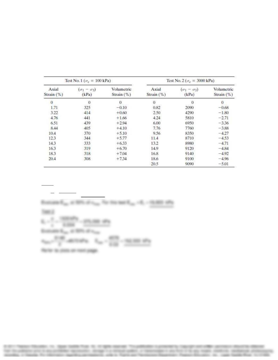
12-6. The results of two CD triaxial tests at different confining pressures on a medium dense,
cohesionless sand are summarized in the table below. The void ratios of both specimens were
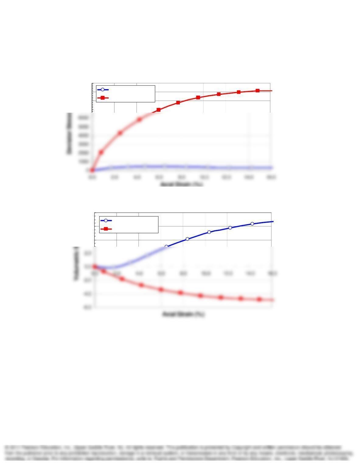
approximately the same at the start of the test. Plot on one set of axes the principal stress
difference versus axial strain and volumetric strain [Eq. (12.4)] versus axial strain for both tests.
Estimate the initial tangent modulus of deformation, the “50%” secant modulus, and the strain at
failure for each of these tests.
SOLUTION:
t
Test 1
325 kPa
E19,006kPa
0.0171
continued on next page
An Introduction to Shear Strength Chapter 12
12-6 continued.
7000
8000
9000
10000
Test 1 at 100 kPa
Test 2 at 3000 kPa
4.0
6.0
8.0
)
Test 1 at 100 kPa
Test 2 at 3000 kPa
An Introduction to Shear Strength Chapter 12
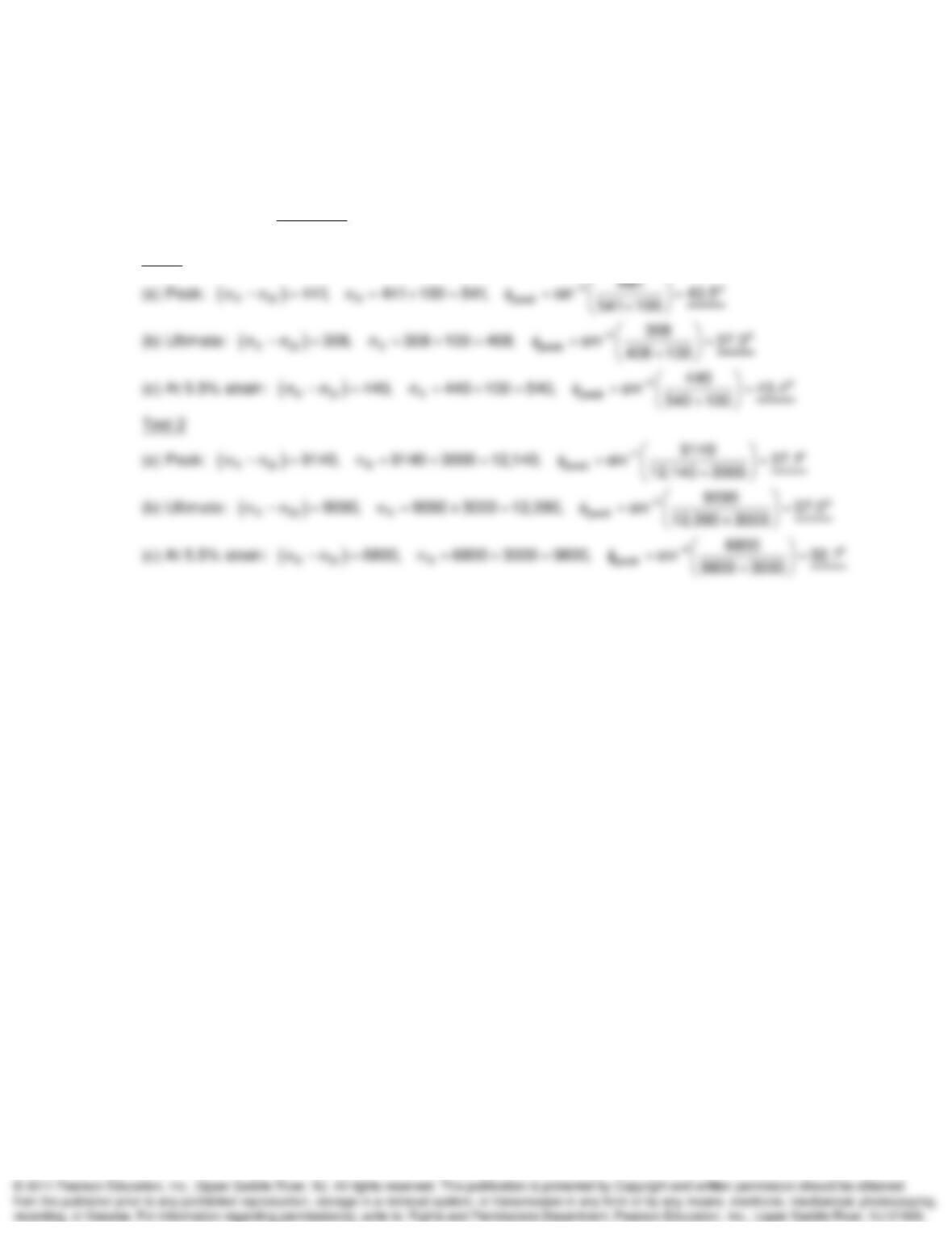
12-7. For the two tests of Problem 12.6, determine the angle of internal friction of the sand at (a)
peak compressive strength, (b) at ultimate compressive strength, and (c) at 5.5% axial strain.
SOLUTION:
1f 3 f
1f 3 f
Eq. (11.13) sin
Test 1
An Introduction to Shear Strength Chapter 12
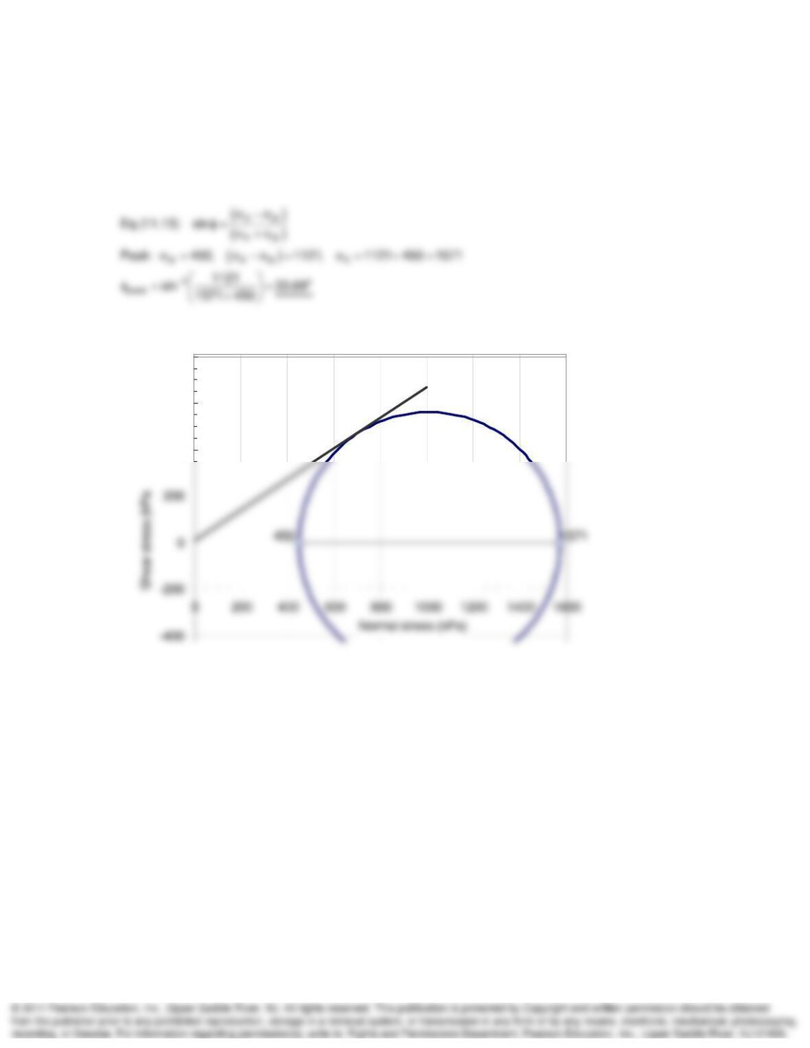
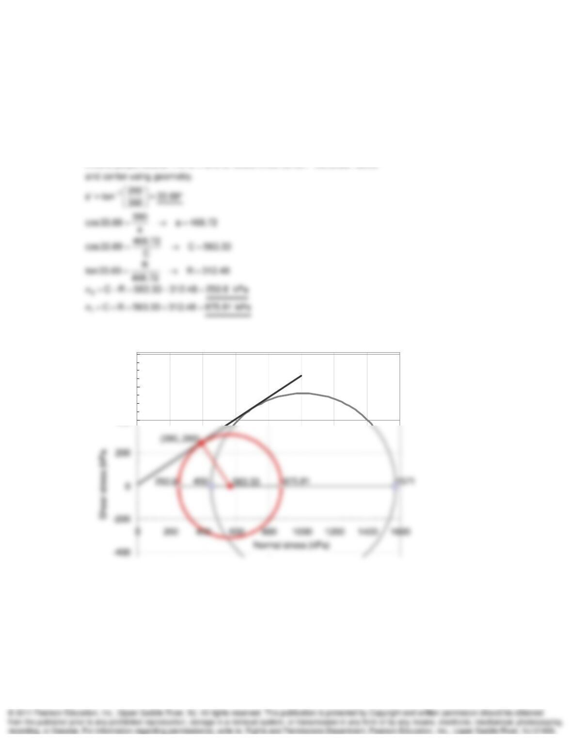
12-8. A sand is hydrostatically consolidated in a triaxial test apparatus to 450 kPa and then
sheared with the drainage valves open. At failure, (
1 –
3) is 1121 kPa. Determine the major and
minor principal stresses at failure and the angle of shearing resistance. Plot the Mohr diagram.
(This problem should be followed by the next one.)
SOLUTION:
400
600
800
An Introduction to Shear Strength Chapter 12
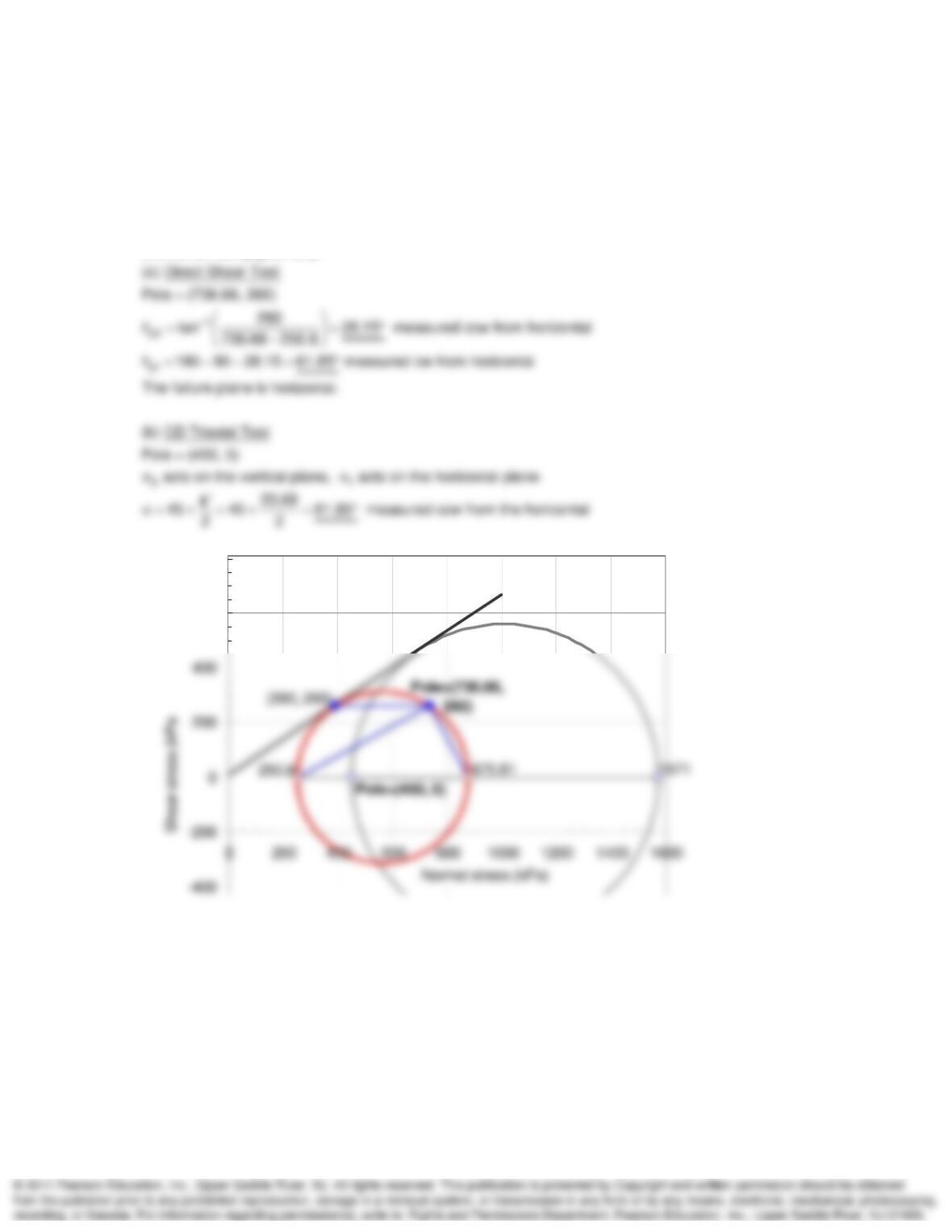
12-9. The same sand as in Problem 12.8 is tested in a direct shear apparatus under a normal
pressure of 390 kPa. The specimen fails when a shear stress of 260 kPa is reached. Determine
the major and minor principal stresses at failure and the angle of shearing resistance. Plot the
Mohr diagram.
SOLUTION:
Plot (390, 260) and draw failure envelope assuming c = 0.
Extend perpendicular line to x axis to locate circle center. Calculate radius
400
600
800
An Introduction to Shear Strength Chapter 12
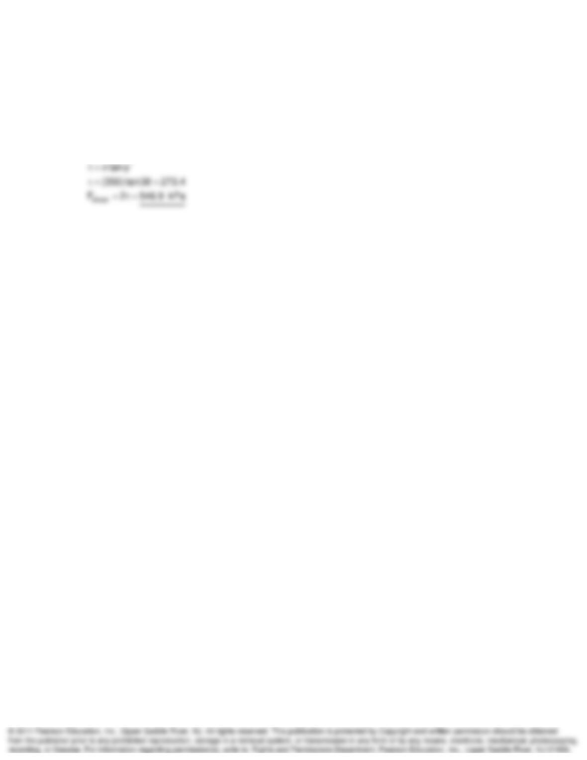
12-10. Indicate the orientations of the major principal stress, the minor principal stress, and the
failure plane of the tests in Problems 12.8 and 12.9.
SOLUTION:
Plot (390, 260) and draw failure envelope assuming c = 0.
Extend perpendicular line to x axis to locate circle center. Calculate radius
and center using geometry.
600
800
An Introduction to Shear Strength Chapter 12
12-11. A granular soil is tested in direct shear under a normal stress of 350 kPa. The size of the
specimen is 7.62 cm in diameter. If the soil to be tested is a dense sand with an angle of internal
friction of 38°, determine the size of the force transducer required to measure the shear force with
a factor of safety of 2 (that is, the capacity of the transducer should be twice that required to
shear the sand).
SOLUTION:
An Introduction to Shear Strength Chapter 12
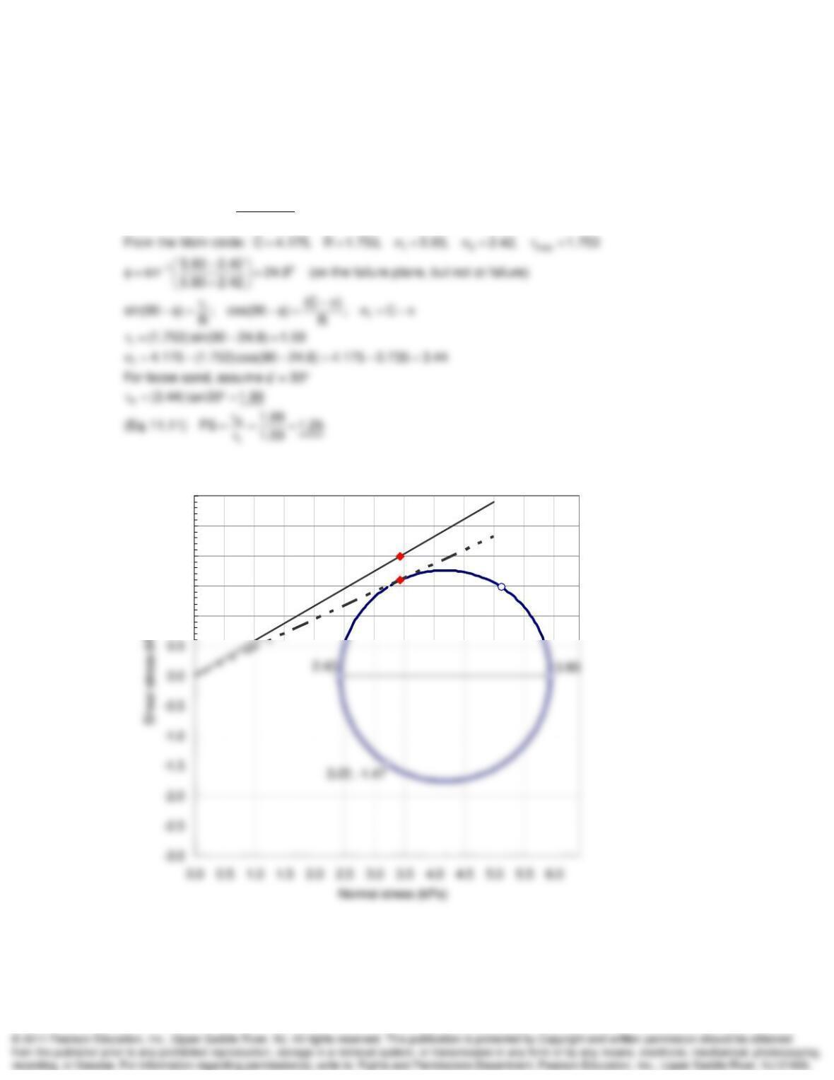
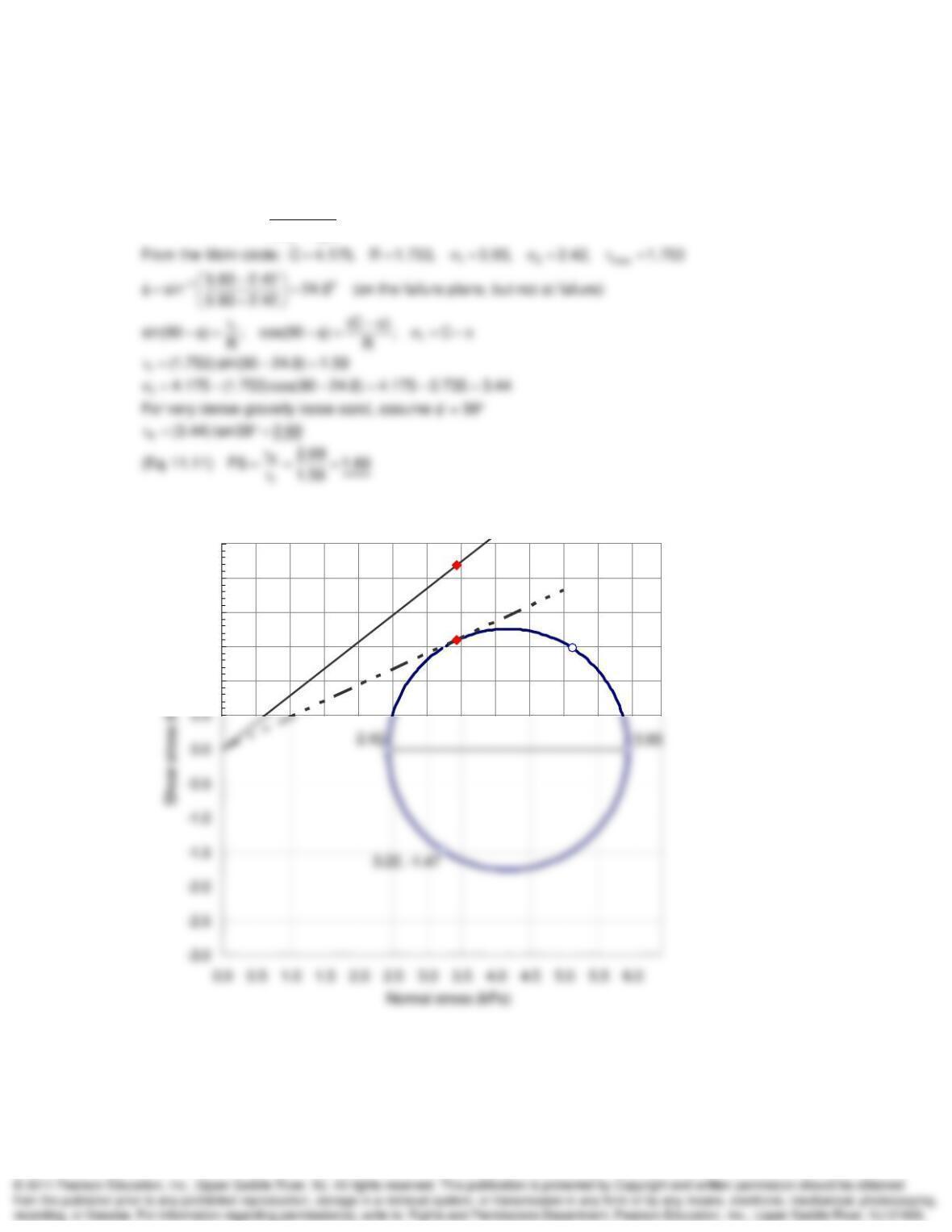
12-12. The stresses induced by a surface load on a loose horizontal sand layer were found to be
v = 5.13 kPa,
v = 1.47 kPa,
h = 3.2 kPa,
h = -1.47 kPa. By means of Mohr circles, determine if
such a state of stress is safe. Use Eq. (11.11) for the definition of factor of safety.
SOLUTION:
1f 3 f
1f 3 f
Eq. (11.13) sin
5.13, 1.47
3.44, 1.59
3.44, 1.99
1.0
1.5
2.0
2.5
3.0
An Introduction to Shear Strength Chapter 12
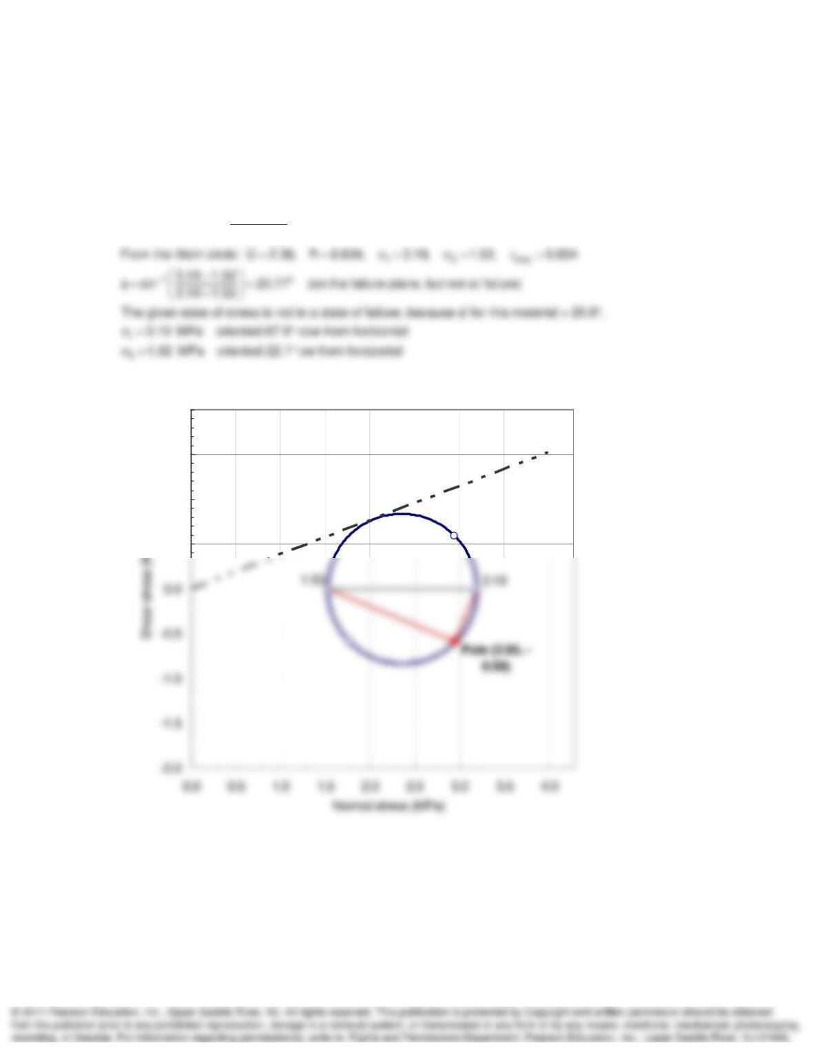
12-13. If the same stress conditions as in Problem 12.12 act on a very dense gravelly sand, is
such a state safe against failure?
SOLUTION:
1f 3 f
1f 3 f
Eq. (11.13) sin
5.13, 1.47
3.44, 1.59
3.44, 2.69
1.0
1.5
2.0
2.5
3.0
An Introduction to Shear Strength Chapter 12
12-14. The effective normal stresses acting on the horizontal and vertical planes in a silty gravel
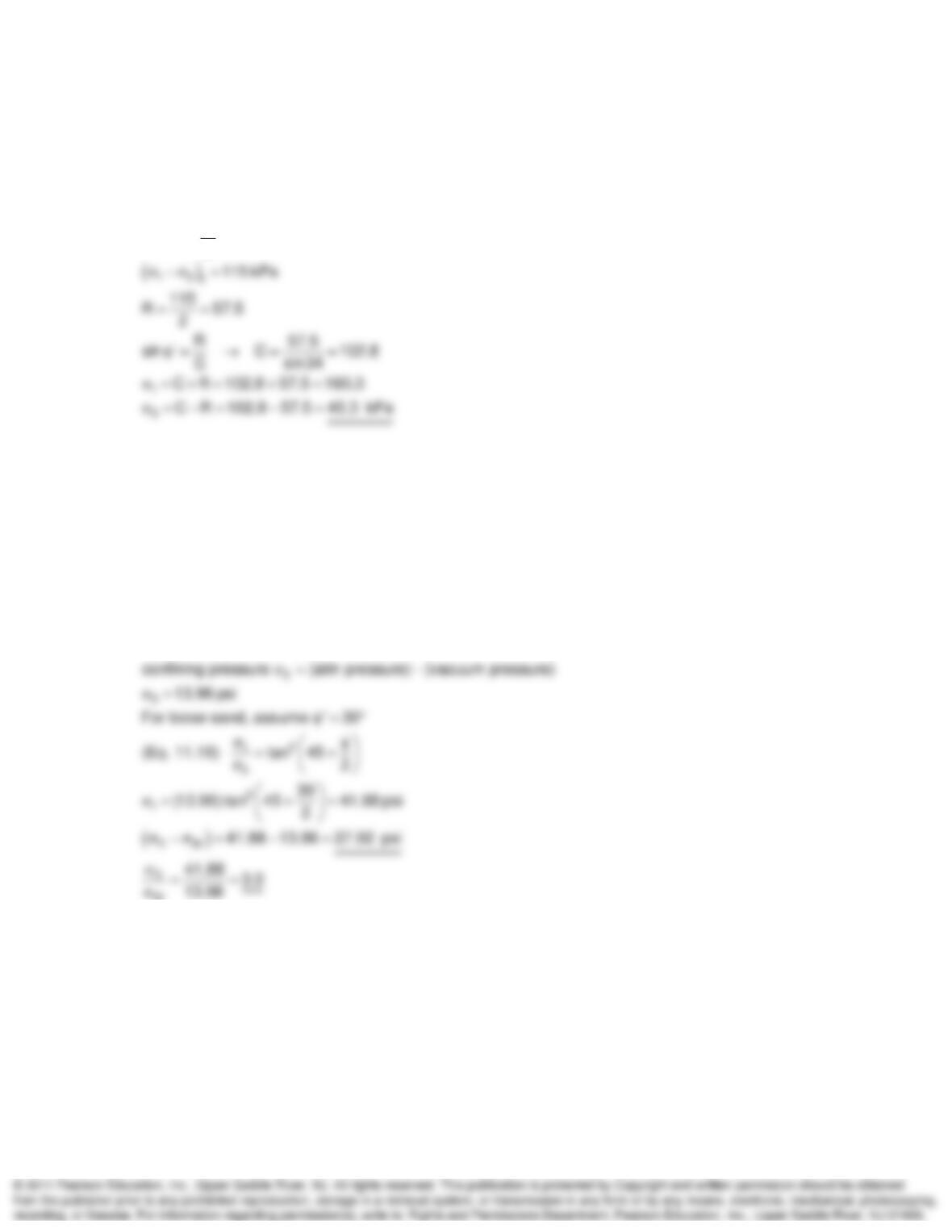
soil are 1.77 MPa and 2.95 MPa, respectively. The shear stress on these planes is
0.59 MPa.
For these conditions, what are the magnitude and direction of the principal stresses? Is this a
state of failure?
SOLUTION:
1f 3 f
1f 3 f
Eq. (11.13) sin
0.5
1.0
1.5
2.0
An Introduction to Shear Strength Chapter 12
12-15. A specimen of dense sand tested in a triaxial CD test failed along a well-defined failure
plane at an angle of 62° with the horizontal. Find the effective confining pressure of the test if the
principal stress difference at failure was 115 kPa.
SOLUTION:
‘
45 62 ‘ 34
2
12-16. A dry loose sand is tested in a vacuum triaxial test in which the pore air pressure of the
specimen is lowered below gage pressure to within about 95% of -1 atm. Estimate the principal
stress difference and the major principal stress ratio at failure.
SOLUTION:
1atm 14.7 psi (0.95)( 14.7) 13.96 psi
3f