Problem 12.1
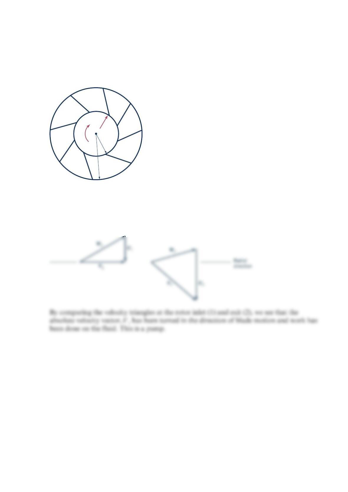
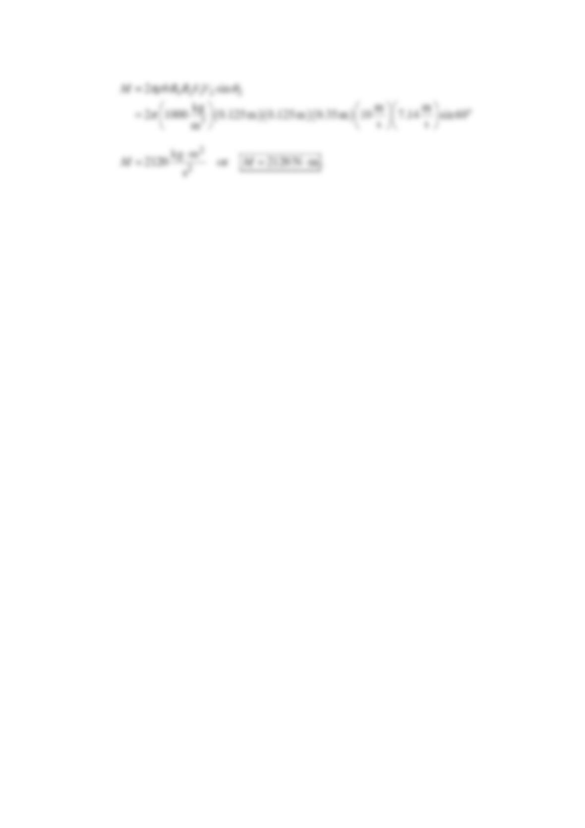
The rotor shown in the figure below rotates clockwise. Assume that the fluid enters in the
radial direction and the relative velocity is tangent to the blades and remains constant
across the entire rotor. Is the device a pump or a turbine? Explain.
Solution 12.1
=
1
2
WW
according to the problem statement and >
21
UU
since >
21
.rr
Thus a reasonable set
of velocity diagrams for this situation looks like.
ω
r1
V1
r2
Problem 12.2
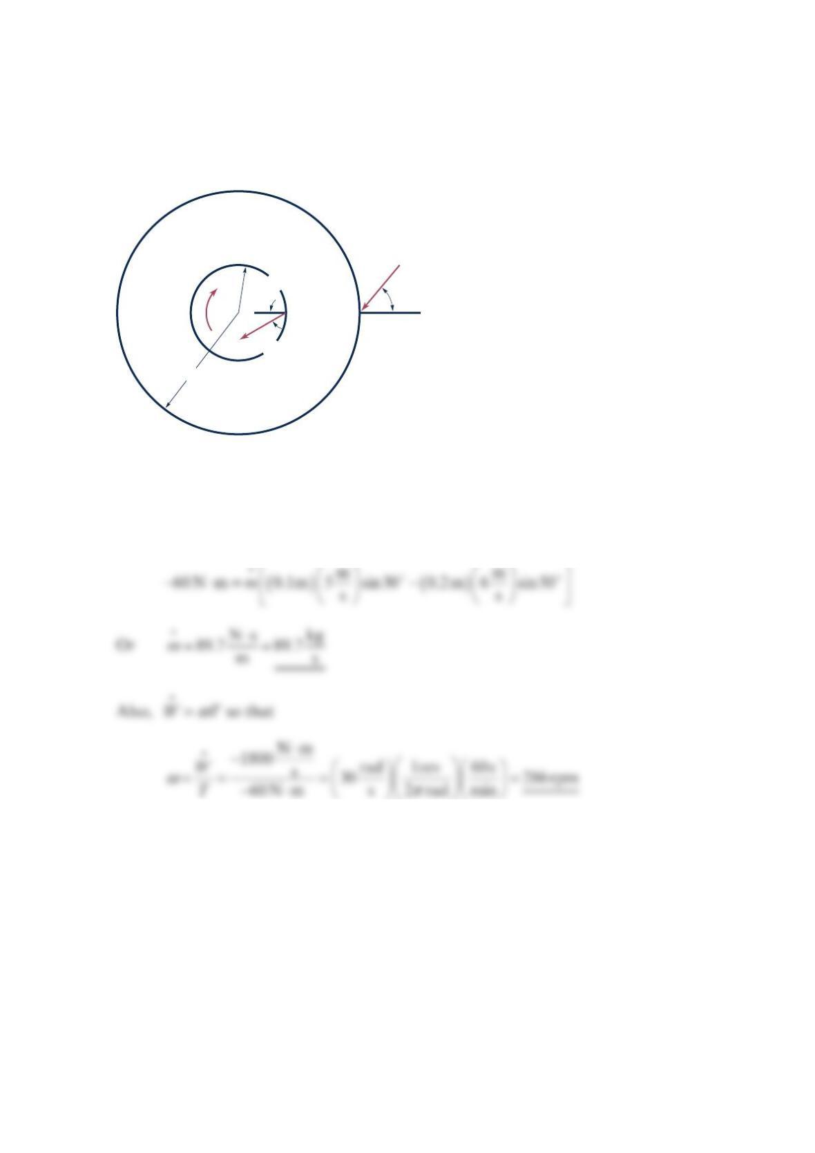
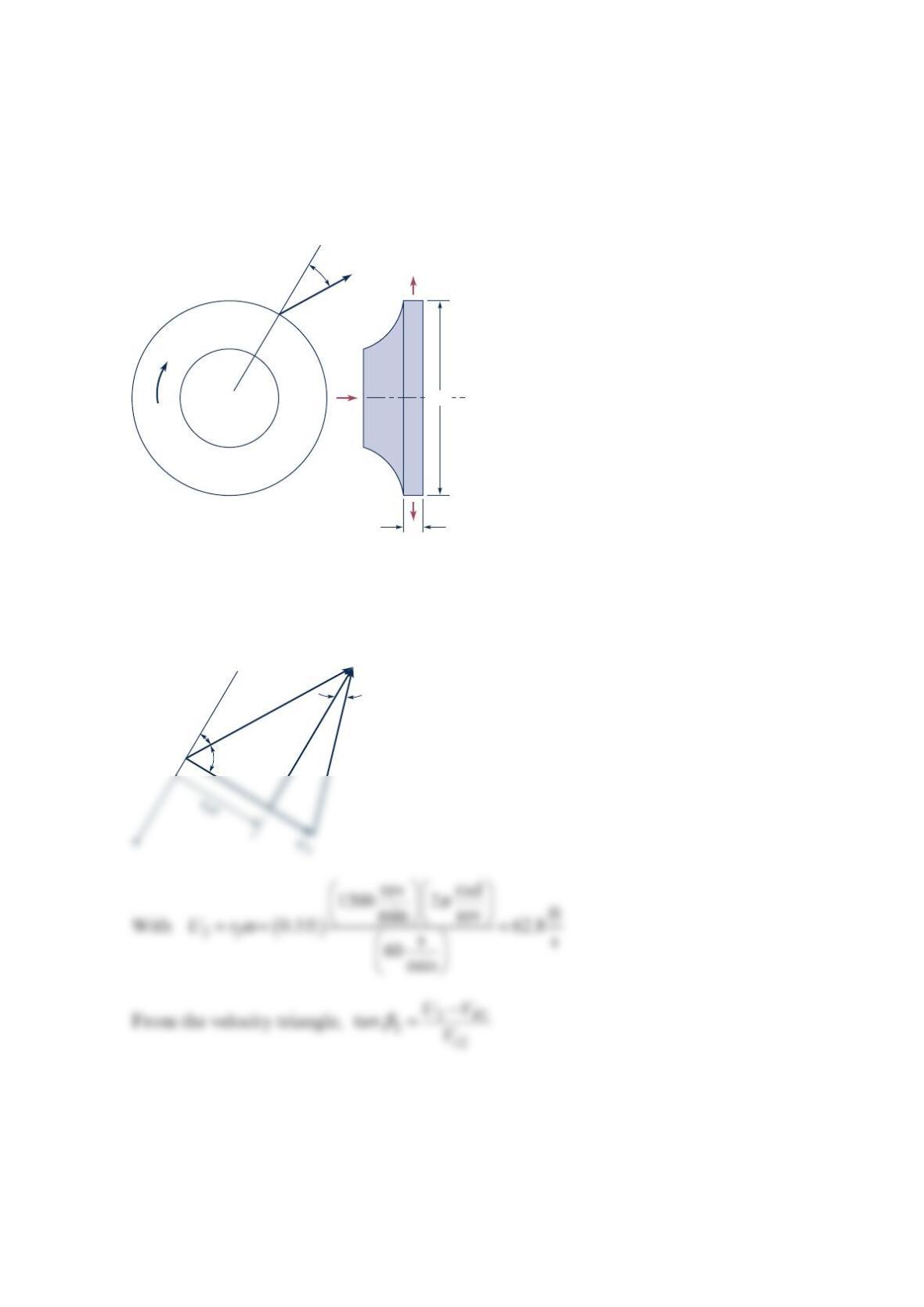
The measured shaft torque on the turbomachine shown in the figure below is
−
⋅60 N m
when the absolute velocities are as indicated. Determine the mass flowrate. What is the
angular velocity if the magnitude of the shaft power is ⋅
1
800 N m / s? Is this machine a pump
or a turbine? Explain.
Solution 12.2
()
θθ
=−
22 11
TmrV rV
or with the given data
+
ω
30°
r
2
= 0.1 m
r
1
= 0.2 m
V
2
= 5 m/s
V
1
= 6 m/s
50°
Problem 12.3
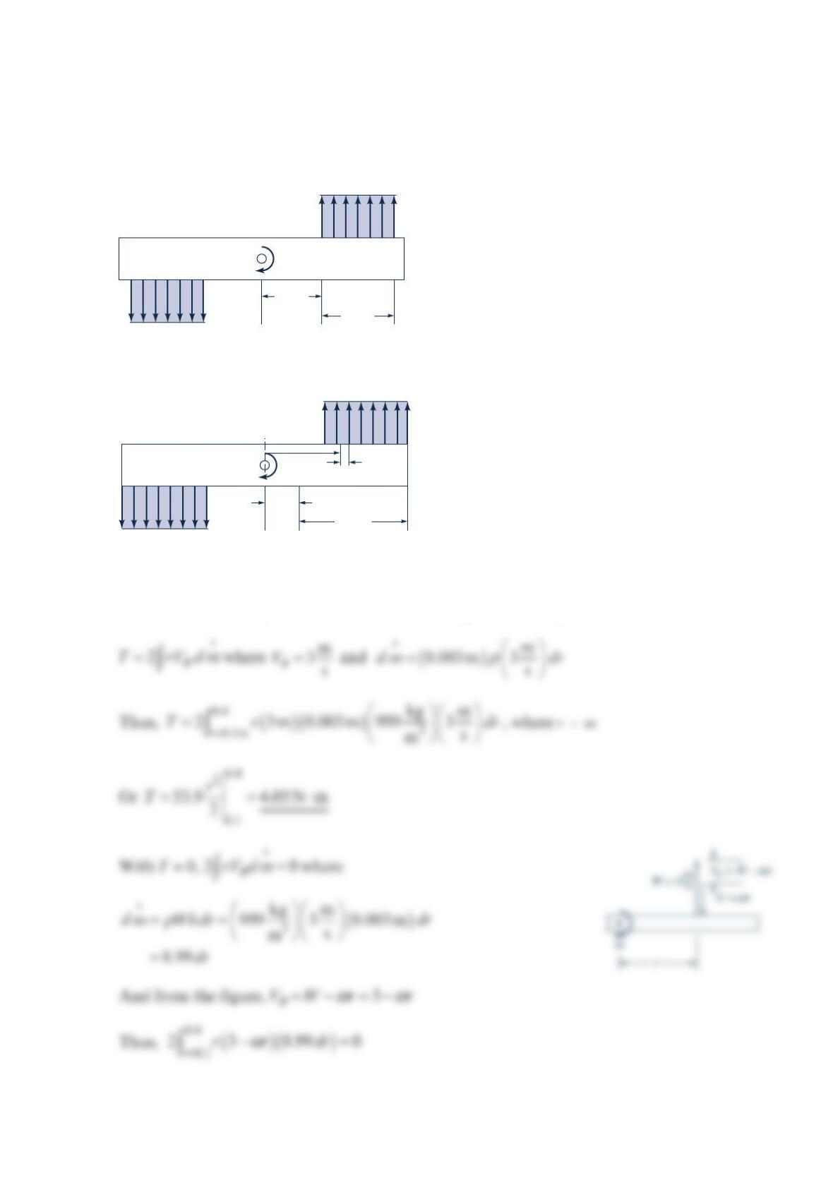
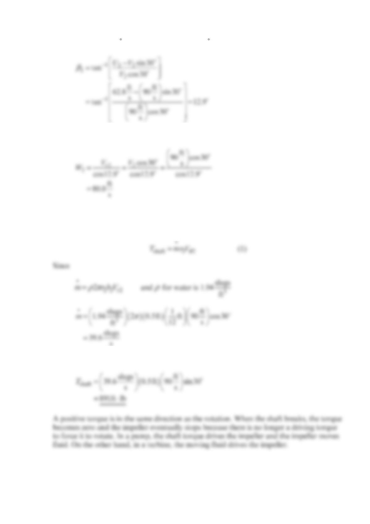
Uniform horizontal sheets of water of 3-mm thickness issue from the slits on the rotating
manifold shown in the figure below. The velocity relative to the arm is a constant
along each slit. Determine the torque needed to hold the manifold stationary. What would
the angular velocity of the manifold be if the resisting torque is negligible?
Solution 12.3
Stationary:
()
θθ
=−
22 11
TmrV rV
For this continuously distributed outflow with
θ
=
10
V
the torque becomes
3
m/s
ω
0.1 m
3 m/s
0.3 m
ω
0.1 m
3 m/s
dr
r
0.3 m
Problem 12.4
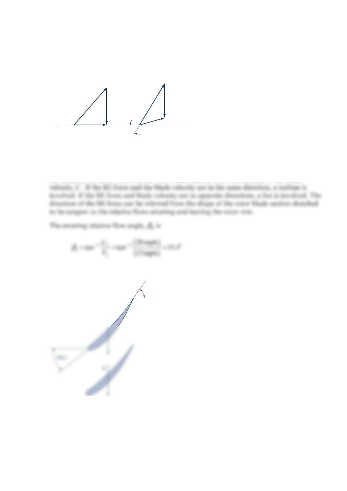
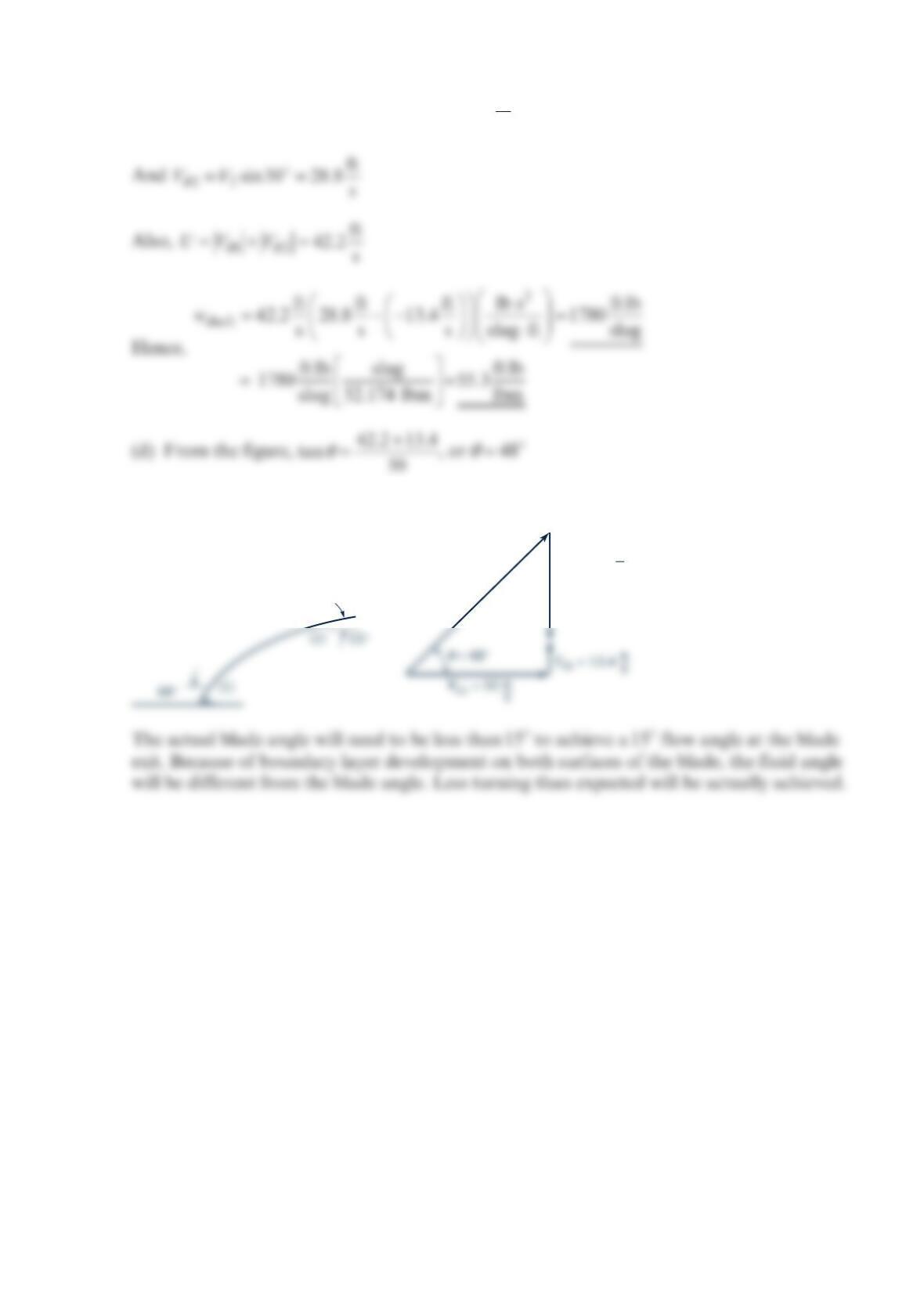
At a given radial location, a 15-mph wind against a windmill results in the upstream (1)
and downstream (2) velocity triangles shown in the figure below. Sketch an appropriate
blade section at that radial location and determine the energy transferred per unit mass of
fluid.
Solution 12.4
We can determine whether the axial flow turbomachine is a turbine or a fan by comparing
the direction of the lift force on the rotor blade section with the direction of the blade
Thus, the rotor blade sections sketched below are appropriate
60°
V1 = 15 mph
W1
W2
V2
U1 = 20 mph
U2 = 20 mph
|W2| = |W1|
60°
Lift
force
Since the lift force acting on each rotor blade section is in the same direction as the blade
velocity, we conclude that this turbomachine is a turbine. The energy transferred per unit
mass is the shaft work per unit mass, shaf
t
w, which we can determine with Euler’s Equation.
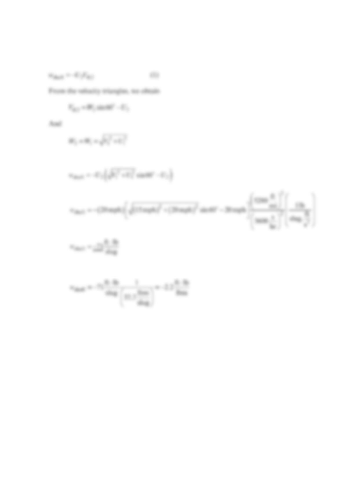
Thus
Thus
or
Problem 12.5
Sketch how you would arrange four 3-in.-wide by 12-in.-long thin but rigid strips of sheet
metal on a hub to create a windmill. Discuss, with the help of velocity triangles, how you
would arrange each blade on the hub and how you would orient your windmill in the wind.
Solution 12.5
Problem 12.6
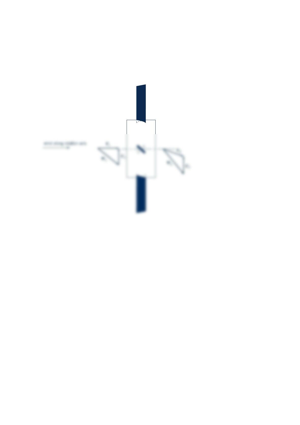
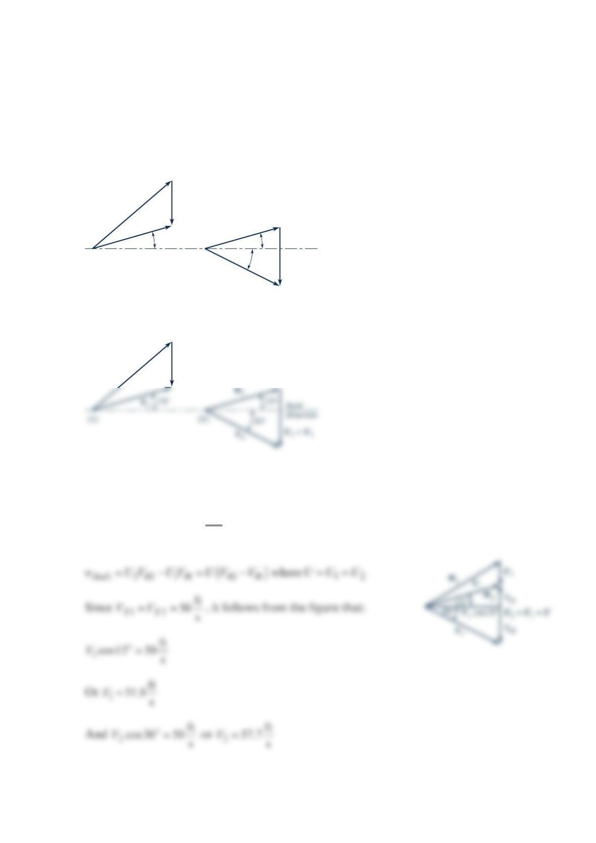
Sketched in the figure below are the upstream [section (1)] and downstream [section (2)]
velocity triangles at the arithmetic mean radius for flow through an axial-flow
turbomachine rotor. The axial component of velocity is 50 ft/s at sections (1) and (2).
(a) Label each velocity vector appropriately. Use
V
for absolute velocity,
W
for relative
velocity, and
U
for blade velocity. (b) Are you dealing with a turbine or a fan? (c) Calculate
the work per unit mass involved. (d) Sketch a reasonable blade section. Do you think that
the actual blade exit angle will need to be less or greater than °
1
5? Why?
Solution 12.6
See figure above.
()()
θθ θθ
=−= −
22 11 mean 2 1
TmrV rV mr V V
where
θ
>
20
V
and
θ
<
1
0
V(see figure above) Thus,
>0.T The machine is a fan.
15°
(1)
15°
(2)
Axial
direction
30°
W1
U1
So that
θ
=− =− =−
11
ft
sin15 51.8sin15 13.4 s
VV
Thus, the blade shape is shown:
W1
V1
= 42.2
ft
s
Problem 12.7
The radial component of velocity of water leaving the centrifugal pump sketched in the
figure below is 45ft/s . The magnitude of the absolute velocity at the pump exit is 90 ft/s .
The fluid enters the pump rotor radially. Calculate the shaft work required per unit mass
flowing through the pump.
Solution 12.7
θθ
=−
shaft 2 2 1
1
wUVUV
also
Since the fluid enters radially,
θ
=
10
V
so that Eq. (12.5) becomes
From Fig. 12.8 (c)
3000
rpm
0.2 ft
0.5 ft
V
1
+
V
2
= 90 ft/s
V
r2
= 45 ft/s
Thus
We proceed to calculate the component velocities
For the entering flow
=+= +
22
222
111
ft ft
62.8 112
ss
r
VUV
So =
1
ft
128 s
r
V
Then from Eq. (12.8)
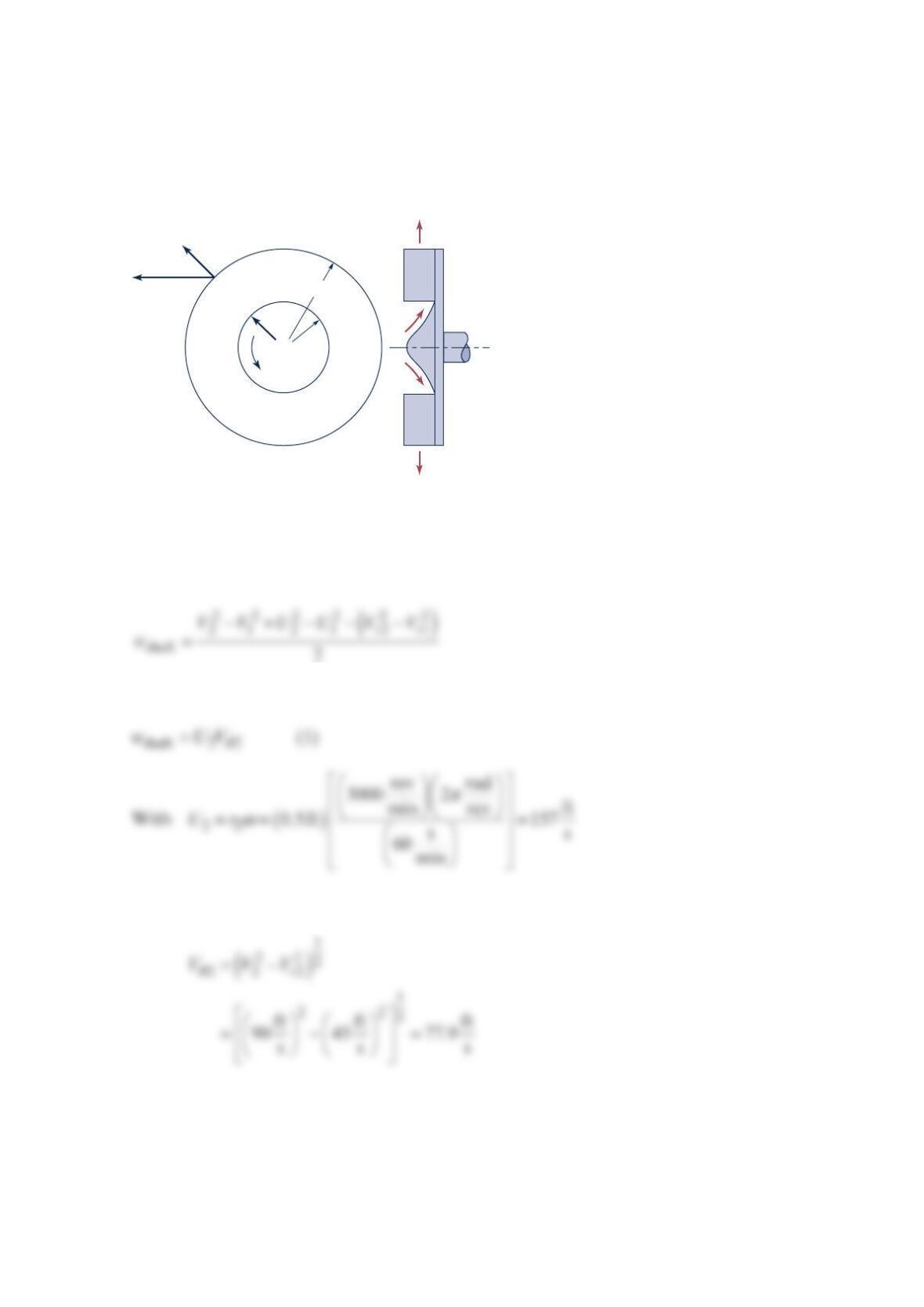
Problem 12.8
Water enters a centrifugal pump with an absolute velocity =
110 m/sV in the radial
direction and leaves with an absolute velocity 2
V, which makes an angle of
θ
=
260 with
the radial direction, as shown in the figure below. The impeller width (perpendicular to the
paper) is =0.125 m
b
, =
10.125
m
R
, and =
20.35 m
R
. Find the input torque required to
drive the pump if there are no friction losses.
Solution 12.8
Apply the continuity equation to a control volume enclosing the impeller. For steady state
conditions,
Now apply the angular momentum equation in the z direction (
⊥
to paper) to a control
volume enclosing the impeller.
R
2
R
1
Impeller
θ
ω
V
1
V
2
𝒯,
2
Or
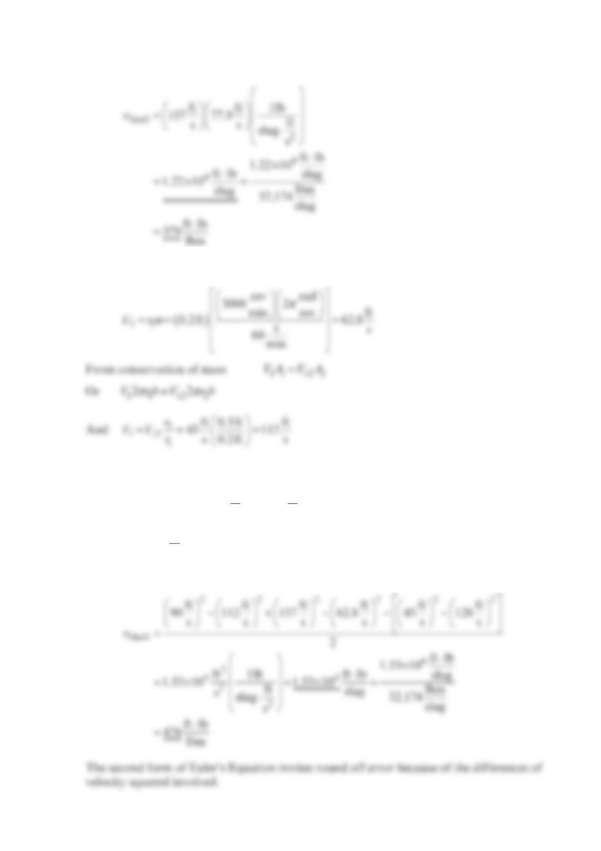
Problem 12.9
A centrifugal pump impeller is rotating at
1
200 rpm in the direction as shown in the figure
below. The flow enters parallel to the axis of rotation and leaves at an angle of °
3
0 to the
radial direction. The absolute exit velocity, 2
V, is 90 ft/s . (a) Draw the velocity triangle for
the impeller exit flow. (b) Estimate the torque necessary to turn the impeller if the fluid is
water. What will the impeller rotation speed become if the shaft breaks?
Solution 12.9
The exit flow velocity triangle can be constructed graphically as indicated below,
+
30°
V
2
1 in.
ω
1 ft
30°
60°
V
2
W
2
V
r2
β
Since
θ
=
22
sin30VV and =
22
cos30
r
VV it follows that
Thus, from the velocity triangle
With
β
2 and
W
known, the velocity triangle is completely specified.
From Eq. (12.9) with
θ
=
10
V
So that from Eq. (1)
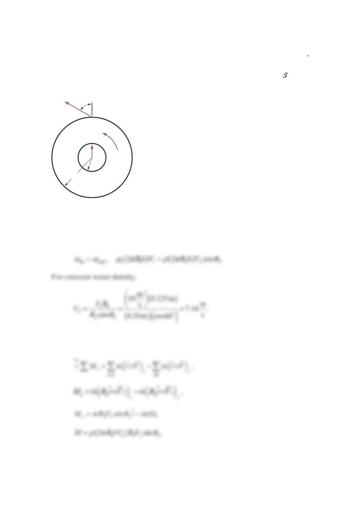
Problem 12.10
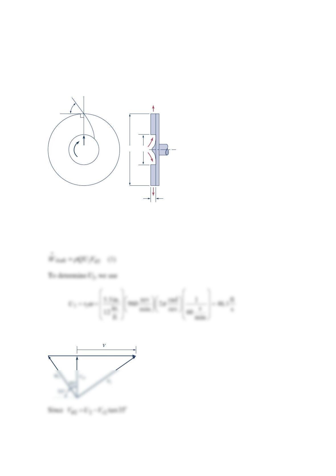
A centrifugal radial water pump has the dimensions as shown in the figure below. The
volume rate of flow is 3
0.25ft / s, and the absolute inlet velocity is directed radially outward.
The angular velocity of the impeller is
9
60 rpm. The exit velocity as seen from a coordinate
system attached to the impeller can be assumed to be tangent to the vane at its trailing edge.
The hydraulic efficiency is
8
2% and the mechanical efficiency is
9
6%. Calculate the power
required to drive the pump.
Solution 12.10
From Eq. (12.11), with
θ
=
10
V
,
To obtain
θ
2
V
, we use the exit velocity triangle shown below.
0.75 in.
55°
960
rpm
V
1
+
Q = 0.25 ft
3
/s
11 in. 3 in.
U
2
2
θ
It follows that
Thus, from Eq. (1)
Or
This is the power transferred to the fluid by the pump impeller. The power required to drive
the pump is
Problem 12.11
Water is pumped with a centrifugal pump, and measurements made on the pump indicate
that for a flowrate of
2
40 gpm the required input power is 6 hp. For a pump efficiency of
62%, what is the actual head rise of the water being pumped?
Solution 12.11
From Eq. (12.23), the pump efficiency is given by the equation
So that
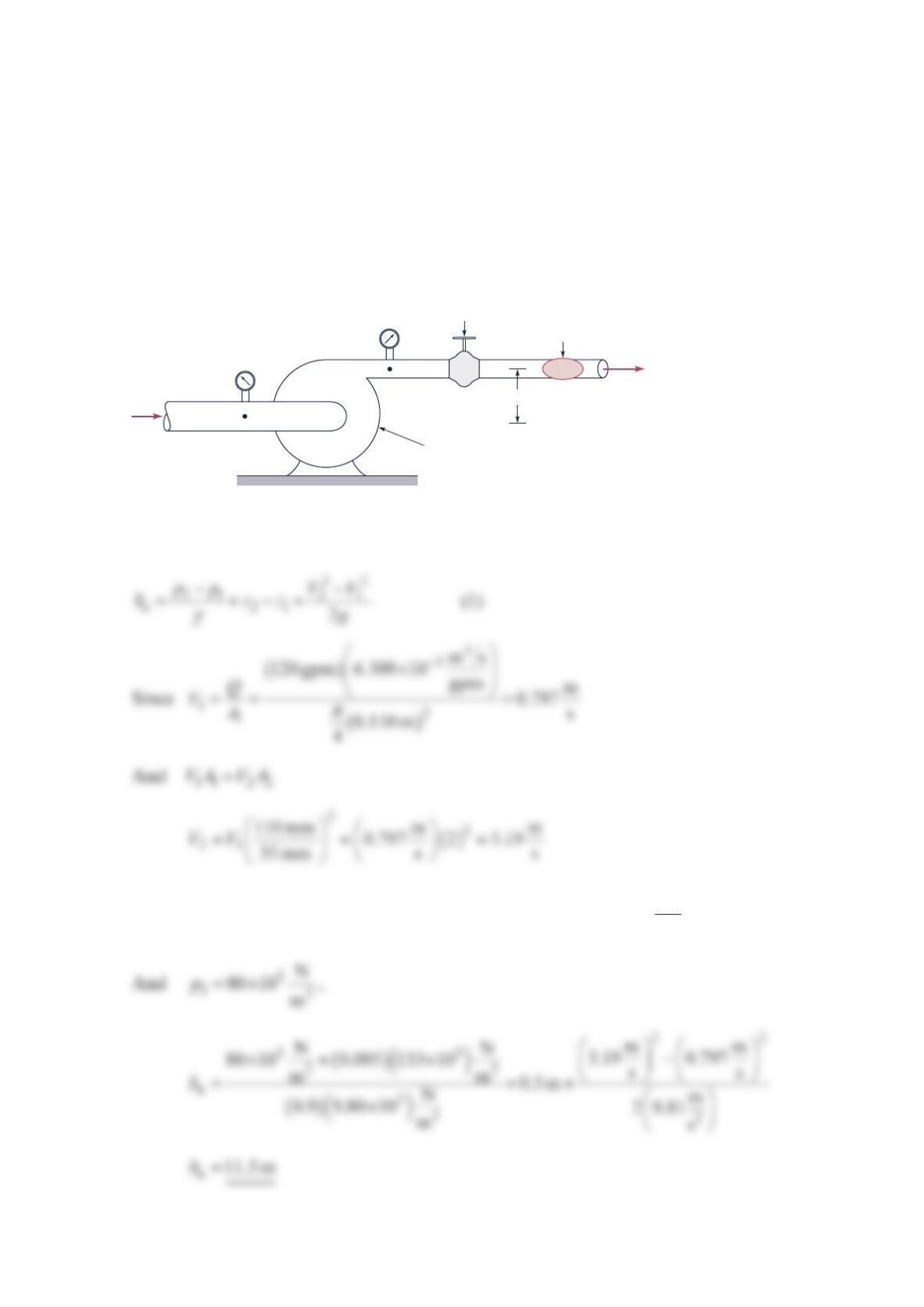
Problem 12.12
The performance characteristics of a certain centrifugal pump are determined from an
experimental setup similar to that as shown in the figure below. When the flowrate of a
liquid
()
=0.9SG through the pump is
1
20 gpm, the pressure gage at (1) indicates a vacuum
of
9
5 mm of mercury and the pressure gage at (2) indicates a pressure of
8
0 kPa. The
diameter of the pipe at the inlet is
1
10 mm and at the exit it is
5
5 mm. If −=
21
z
z0.5 m
,
what is the actual head rise across the pump? Explain how you would estimate the pump
motor power requirement.
Solution 12.12
From Eq. (12.19)
Thus, from Eq. (1), with
()()
()
γ
=− =− ×
3
1HgHg 3
N
0.095 m 133 10 m
ph
z2 – z1
(1)
(2)
Flowrate meter
Valve for varying
system resistance
Behind pump (out of sight):
Drive shaft and motor with
speed and power measurement
Q
To estimate the pump motor power requirement use Eq. (12.23)