where
ρ
⋅
⋅
== =
3
3
slugs ft slugs
1.94 0.0109 0.0211
ss
ft
mQ
Thus,
and
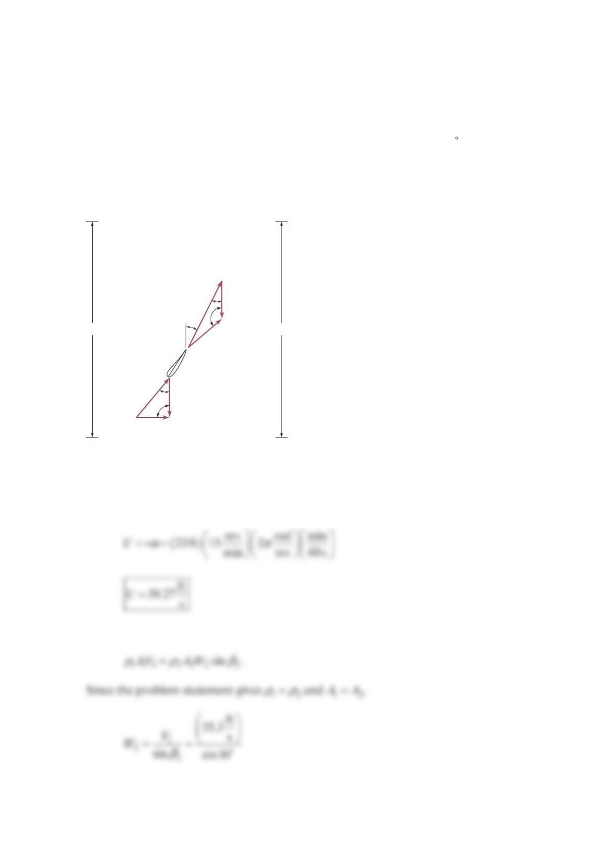
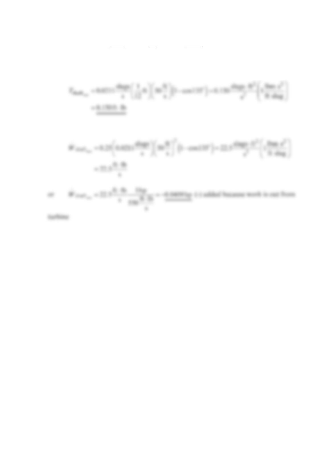
Problem 12.51
A windmill has an approach velocity =
124 mph (35.3ft/s)V and a blade diameter of 100 ft .
The blade rotates at 15rpm. The figure below shows a blade cross-sectional profile and the
velocity diagrams for a short section of the blade at a radius of =25.0 ftr. The outlet
relative velocity 2
W
is tangent to the blade at the outlet so
ββ
=′=
22
30 . The air density is
constant as it flows over the blade. Assume that the flow area for the mass flowrate that
interacts with this short section of the blade is the same upstream and downstream of the
blade (i.e., =
1
2
A
A). Find the velocity diagram downstream of the blade by finding ,
U
2
W
,
2
,
V and
α
2.
Solution 12.51
The blade velocity at =25ftr is
Conservation of mass for a control volume enclosing the short section gives
2
A
U
U
W
2
W
1
V
2
V
1
1
β
2
β
′
2
β
1
α
2
α
A1A2
Blade
The velocity 2
V is found from the law of cosines
The angle
α
2 is found from the law of cosines,
As a check, the law of cosines gives
U
W
2
β
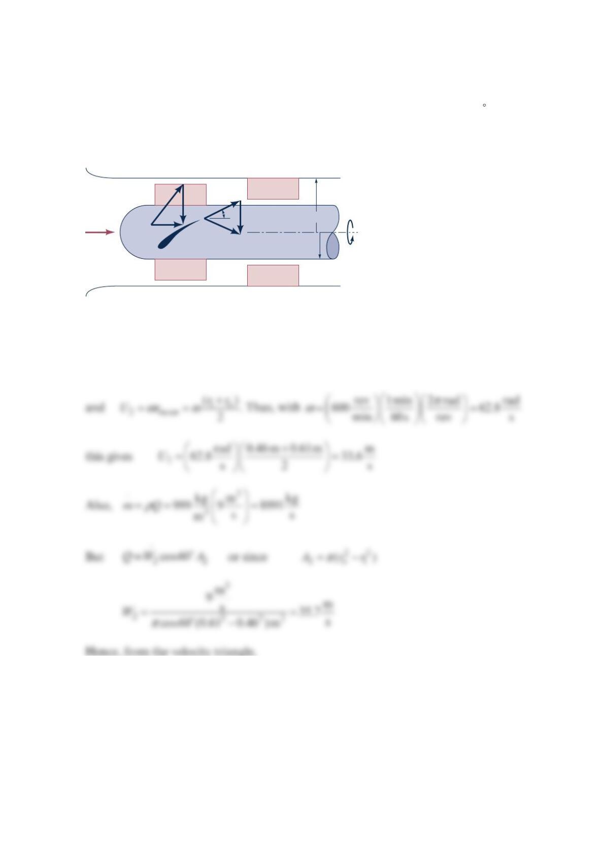
Problem 12.52
The single-stage, axial-flow turbomachine shown in the figure below involves water flow at
a volumetric flowrate of 3
9m /s. The rotor revolves at 600rpm. The inner and outer radii
of the annular flow path through the stage are 0.46 and 0.61m , and
β
=
2 60 . The flow
entering the rotor row and leaving the stator row is axial when viewed from the stationary
casing. Is this device, a turbine or a pump? Estimate the amount of power transferred to or
from the fluid.
Solution 12.52
()
θθ
⋅⋅
=−
shaft 22 11
WmUVUV
where
θ
=
10
V
(1)
600
rpm
r
1
= 0.46 m
r
0
= 0.61 m
Q =
9 m
3
/s
β
2
W
2
U
2
V
2
V
1
U
1
W
1
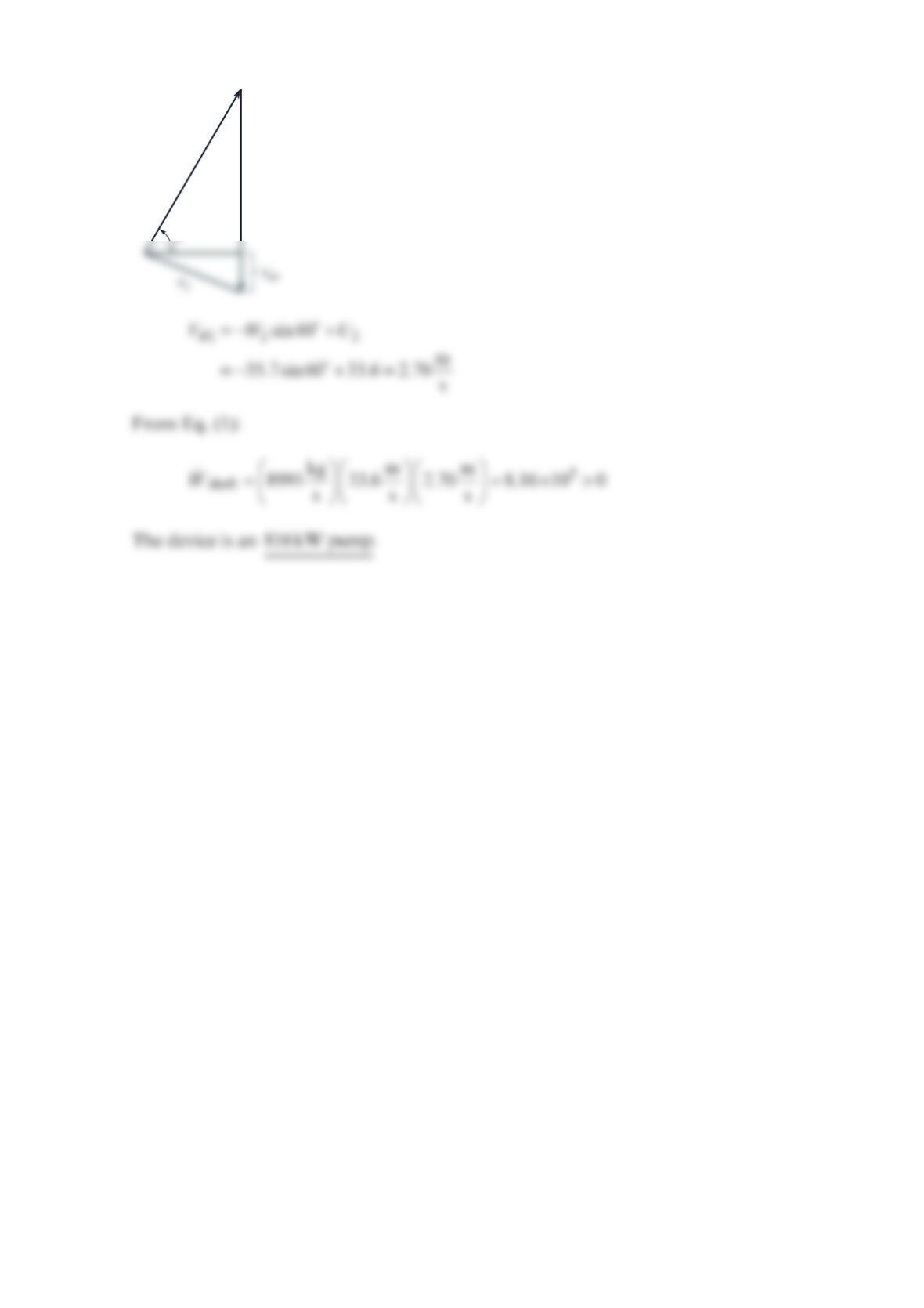
W2
= 35.7
U2
= 33.6
Problem 12.53
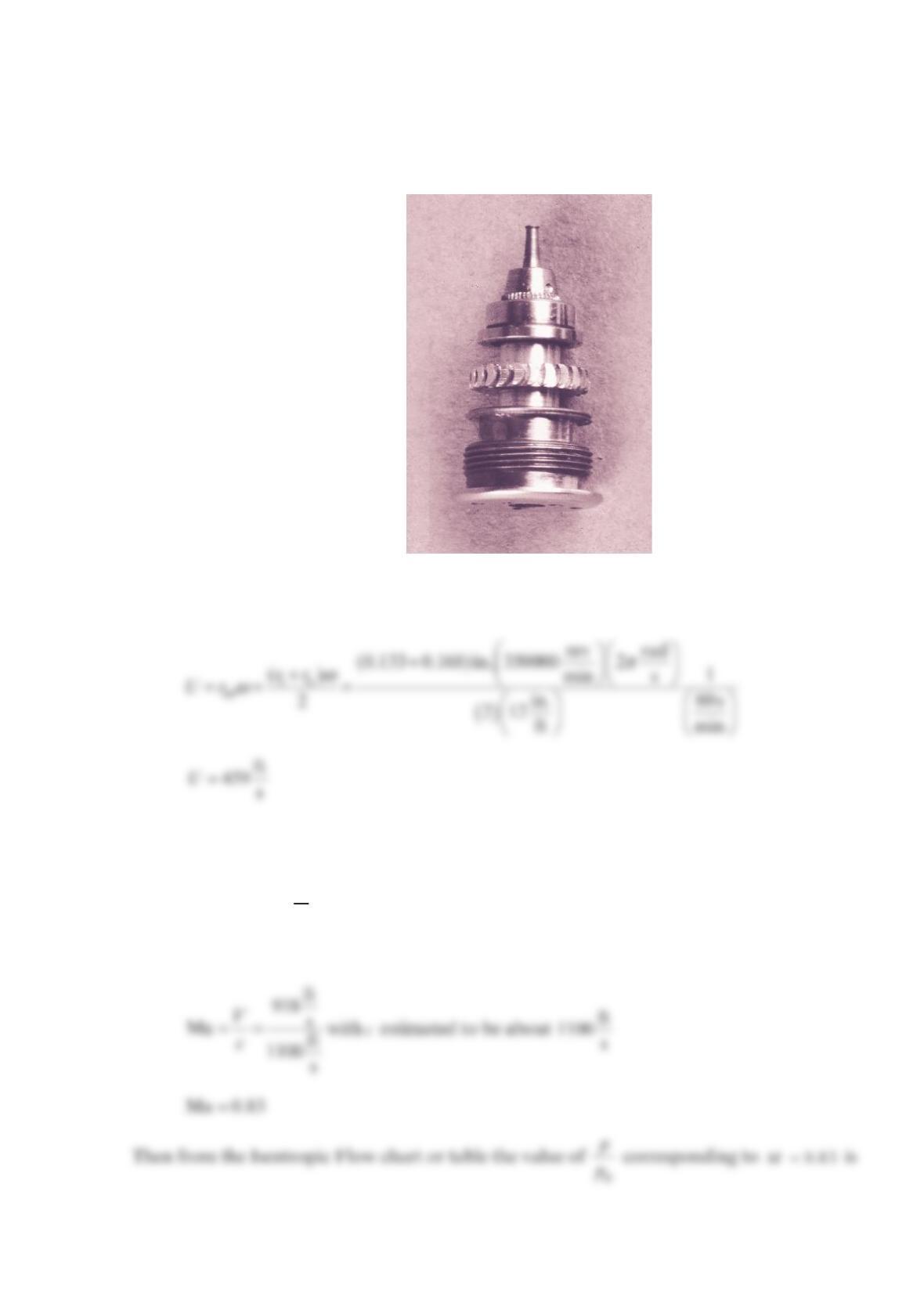
For an air turbine of a dentist’s drill like the one shown in the figure below and discussed in
Example 12.7, calculate the average blade speed associated with a rotational speed of
3
50,000 rp
m
. Estimate the air pressure needed to run this turbine.
Solution 12.53
We calculate the average blade speed, U, from
To estimate the air pressure, o
p
, needed to run this turbine, we estimate that the nozzle exit
velocity is about twice as large as the average blade velocity or
== ft
2 918 s
VU
So, the corresponding Mach number,
M
a, is approximately
Problem 12.54
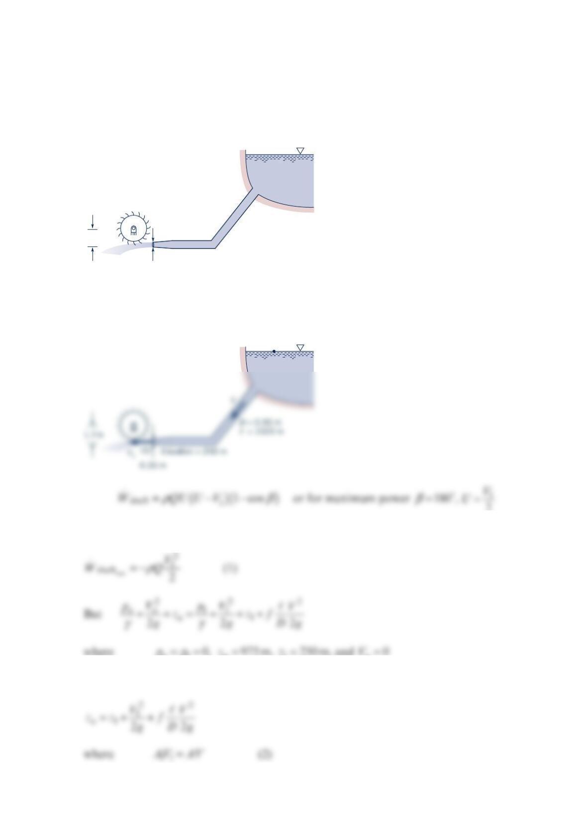
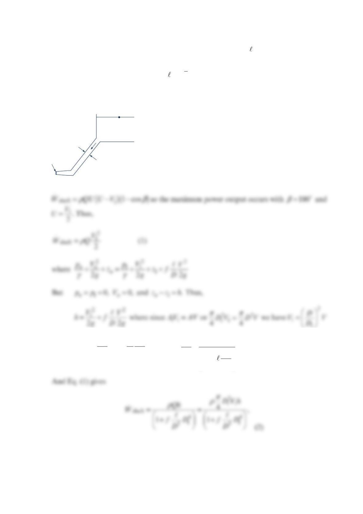
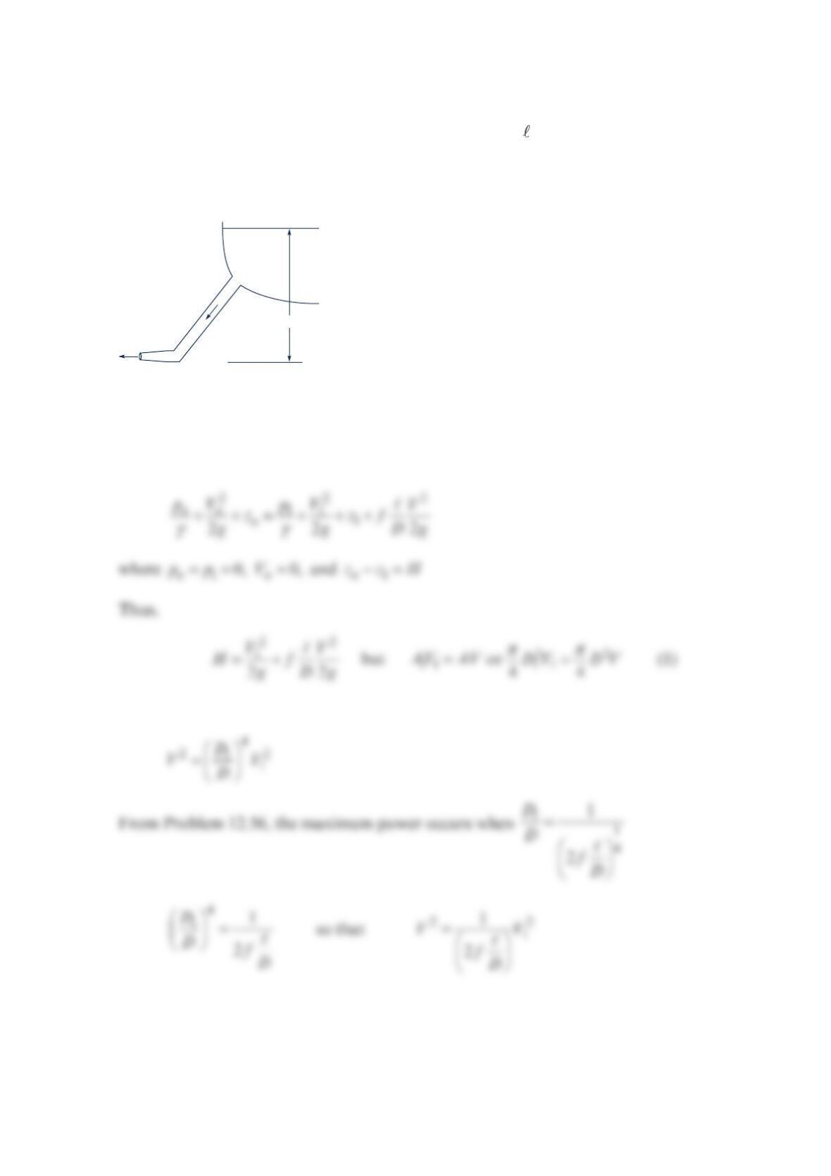
Water for a Pelton wheel turbine flows from the headwater and through the penstock as
shown in the figure below. The effective friction factor for the penstock, control valves, and
the like is 0.032, and the diameter of the jet is 0.20 m . Determine the maximum power
output.
Solution 12.54
2
Thus,
o1
o975 m,z =
1250 m,z and =
o0V
Hence,
Elevation
= 975 m
D = 0.90 m
= 1020 m
1.7 m
Elevation = 250 m
0.20 m
ℓ
Elevation
= 975 m
(0)
so that Eq. (2) becomes:
Hence,
Therefore, from Eq. (1):
Problem 12.55
A Pelton wheel has a diameter of 2 m and develops 500 kW when rotating 180 rpm. What is
the average force of the water against the blades? If the turbine is operating at maximum
efficiency, determine the speed of the water jet from the nozzle and the mass flowrate.
Solution 12.55
D
W
TF
.
shaft 2
ωω
== s
so that at maximum efficiency with
β
=180 and =1
2
V
U this gives
Thus, from Eq. (1):
Problem 12.56
Water to run a Pelton wheel is supplied by a penstock of length and diameter
D
with a
friction factor
f
. If the only losses associated with the flow in the penstock are due to pipe
friction, show that the maximum power output of the turbine occurs when the nozzle
diameter, 1
D
, is given by
()
=4
1
1
/2 /
D
DfD
.
Solution 12.56
Therefore,
24
11
4
1
2
VD
h
f
gD
D
=+
or
2
1
4
1
5
21
Vh
gD
fD
=
+
D
V
D1
(1)
(0)
ℓ
A
but
Thus, from Eqs. (2) and (3):
Note: →
.
shaft 0
W
as →
10
D
and as →∞
1.
D
To find the 1
D
that gives maximum power over
all, set =
.
shaft
1
0
dW
dD
D
Problem 12.57
A Pelton wheel is supplied with water from a lake at an elevation
H
above the turbine. The
penstock that supplies the water to the wheel is of length , diameter
D
, and friction factor
f
. Minor losses are negligible. Show that the power developed by the turbine is maximum
when the velocity head at the nozzle exit is
2
/3H. Note: The result of Problem 12.56 may
be of use.
Solution 12.57
For the flow through the penstock:
so that
D
V
V
1
(1)
(0)
ℓH

Thus, Eq. (1) becomes
Problem 12.58
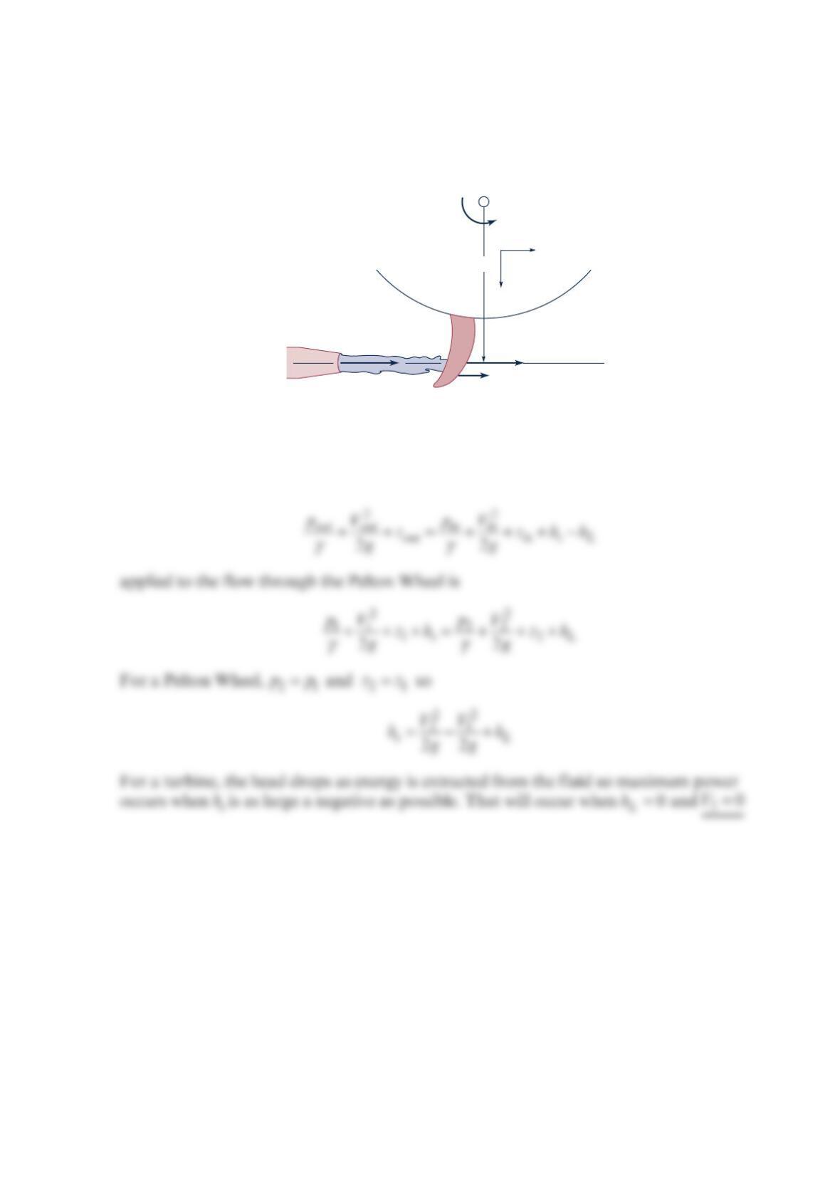
Water flows through the Pelton wheel turbine as shown in the figure below. For simplicity
we assume that the water is turned 180° by the blade. Show, based on the energy equation
[Eq. (5.84)], that the maximum power output occurs when the absolute velocity of the fluid
exiting the turbine is zero.
Solution 12.58
Equation (5.84)
Tangential
V1
V2
Ub
ω
Radial
rm
a
Problem 12.59
A 1-m-diameter Pelton wheel rotates at 300rpm . Which of the following heads (in meters)
would be best suited for this turbine: (a) 2, (b) 5, (c) 40, (d) 70, or (e) 140? Explain.
Solution 12.59
With =1mD and
π
ω
==
rev 1min 2 rad rad
300 31.4 ,
min 60s rev s