PROBLEM 11.68 (Cont.)
[ ]
2
2
,/( ) 0.003 m /(180 W/m K 0.02 m ) 0.042 K/W
t b b hs
R L kW= = ⋅× =
min
3
( )( 1)
8.89 m/s 0.015 m 0.0018 m 10 1.1614 kg/m 1007J/kg K = 2.80 W/K
p wf p
C mc u L S t N c
r
== −−
= × × ×× × ⋅
The NTU is
yielding a heat rate of
The temperature of the air exiting the heat sink is found from
(c) If the air flow velocity is halved,
102
h
D
Gz =
and
2
75.2 W/m Kh= ⋅
COMMENTS: (1) Without accounting for the increase in the air flow temperature, the answer for
Part (a) is (from Problem 3.144) qc = 31.8 W. As expected, the increasing air temperature, as it makes
its way through the heat sink, reduces the heat transfer rate. (2) The heat rate in Part (c) is reduced
PROBLEM 11.69
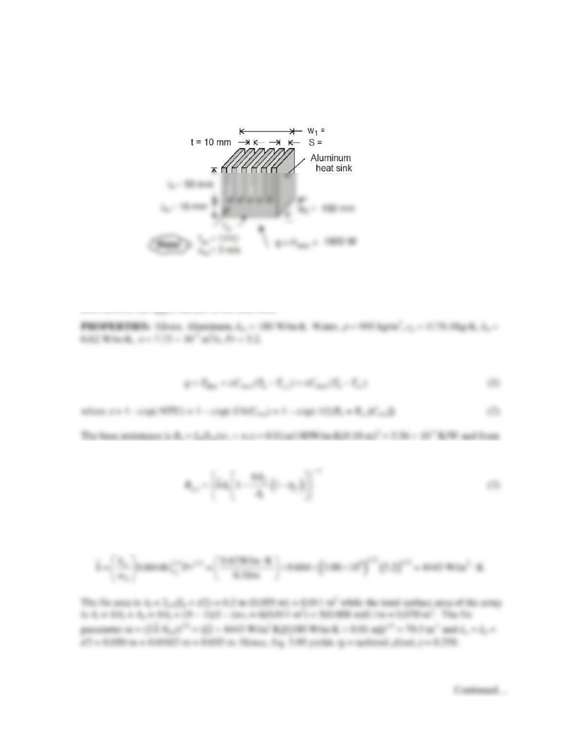
KNOWN: Dimensions of aluminum heat sink. Temperature and velocity of coolant (water) flow
through the heat sink. Power dissipation of electronic package attached to the heat sink.
FIND: Base temperature of heat sink.
SCHEMATIC:
ASSUMPTIONS: (1) Average convection coefficient associated with water flow over fin surfaces
may be approximated as that for a flat plate in parallel flow, (2) All of the electric power is dissipated
by the heat sink, (3) Transition Reynolds number of Rex,c = 5 × 10⁵, (4) Constant properties, (5), Water
does not exit the upper surface of the heat sink.
ANALYSIS: The heat transfer rate is
Eqs. 3.107 and 3.108,
The Reynolds number is Rew2 = u∞w2/
ν
= 3 m/s × 0.10 m/7.73 × 10-7 m2/s = 3.88 × 10⁵, and the flow is
laminar. Hence,
18 mm
100 mm
PROBLEM 11.69 (Cont.)
Hence,
The heat capacity rate is Cmin =
r
(N – 1)Lf(S – t)u∞cp = 995 kg/m3 × (6 – 1) × 0.050 m × (0.018 m –
0.010 m) × 3 m/s × 4178 J/kg⋅K = 24,940.
Equations (1) and (2) can be combined to yield
COMMENTS: (1) The outlet water temperature is Tc,o = Tc,i + Pelec/Cmin = 17°C + 1800 W/24,940
W/K = 17.1°C and the assumption of constant water temperature made in Problem 7.22 is valid. (2)
The hydrodynamic boundary layer thickness at the exit of the heat sink is
δ
= 5w2Rew2
–1/2 = 0.80 mm
PROBLEM 11.70
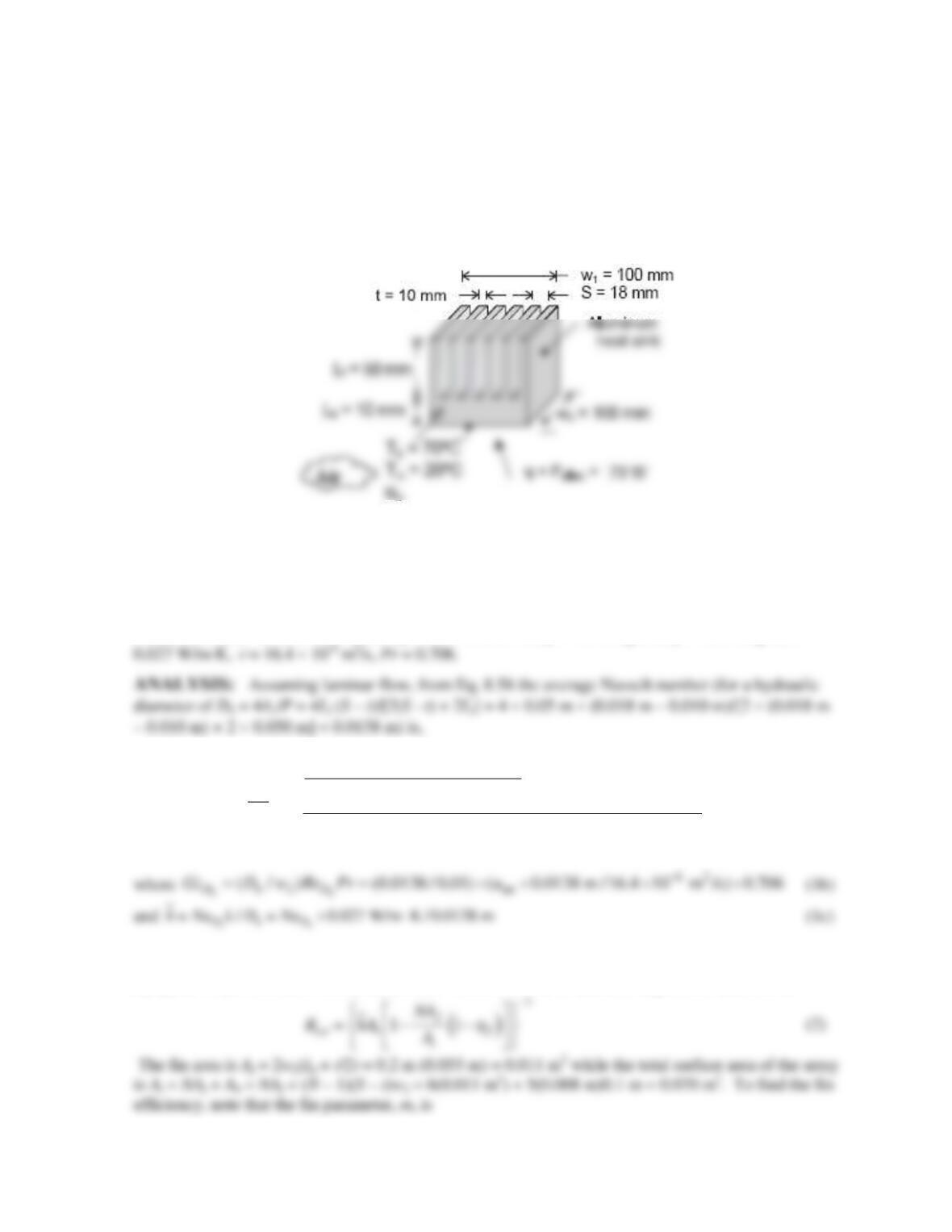
KNOWN: Dimensions of aluminum heat sink. Temperature of air entering the heat sink and specified
base temperature.
FIND: Plot of the allowable power dissipation and air exit temperature as a function of air velocity
over the range 1 m/s ≤ u∞ ≤ 5 m/s.
SCHEMATIC:
ASSUMPTIONS: (1) Average convection coefficient associated with air flow over fin surfaces may
be approximated as that for a channel composed of isothermal parallel plates of width Lf, (2) All of the
electric power is dissipated by the heat sink, (3) Laminar flow, (4) Constant properties, (5), Air does
not exit through the upper surface of the heat sink.
PROPERTIES: Given. Aluminum, khs = 180 W/m⋅K. Air,
r
= 1.145 kg/m3, cp = 1007 J/kg⋅K, k =
()
( )
1
1/3 2/3
1/6 1/6
3.66 0.0499 tanh
tanh 2.264 1.7
tanh 2.432 Pr
hh
h
h
h
h
DD
D
D
D
D
Gz Gz
Gr Gz
Nu
Gz
−
−−
−
+
+
=
(1a)
The total resistance consists of the base and fin resistances in series. The base resistance is Rb =
Lb/khs(w1 × w2) = 0.01m/180W/m⋅K(0.10 m)2 = 5.56 × 10⁻³ K/W and from Eqs. 3.107 and 3.108,
Continued…
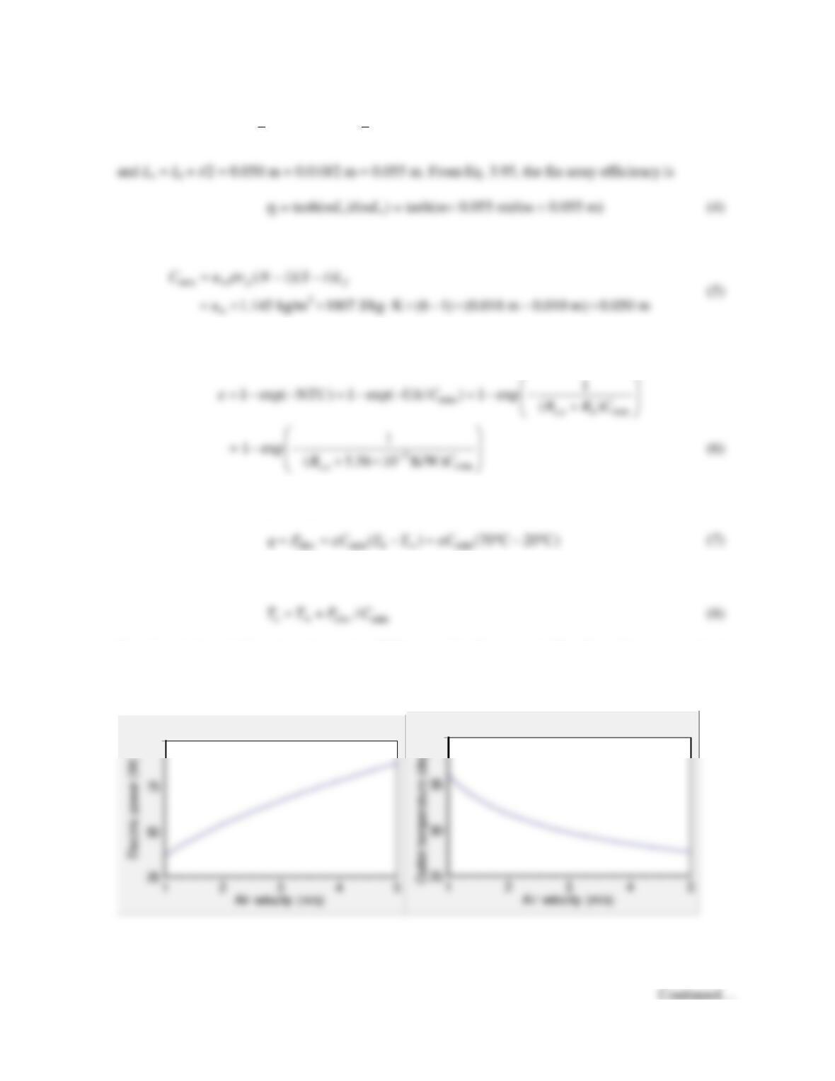
PROBLEM 11.70 (Cont.)
m = (2
h
/khst)1/2 = ([2 ×
h
W/m2⋅K]/[180 W/m⋅K × 0.01 m])1/2 (3)
The minimum heat capacity rate is
and the effectiveness is
The heat transfer rate may be expressed as
and the outlet air temperature is
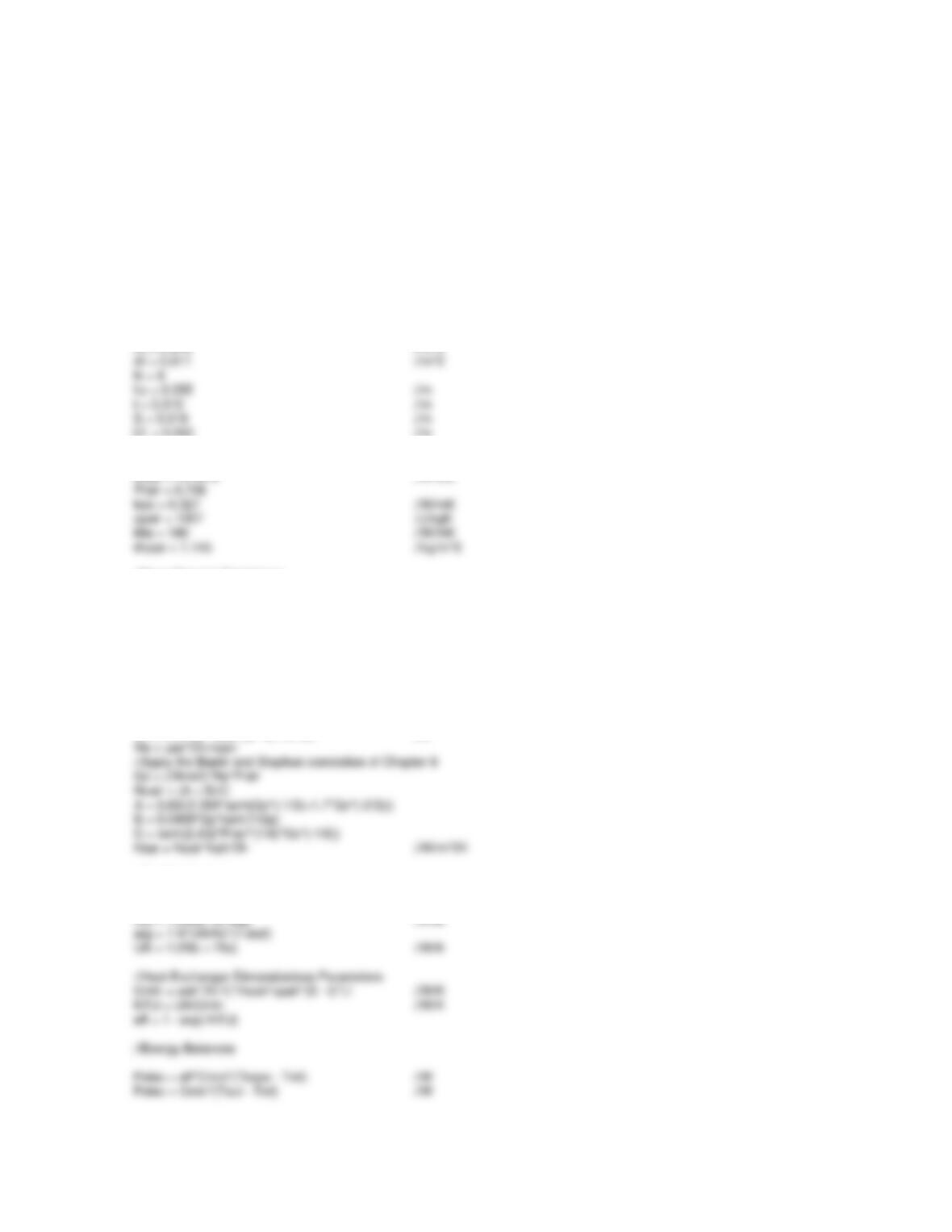
Equations 1 through 7 can be solved using IHT as noted in Comment 1. The allowable power and exit
air temperatures are shown below.
100
40
PROBLEM 11.70 (Cont.)
COMMENTS: (1) The IHT code is shown below. (2) Values of the Reynolds number range from
841 to 4205 for air velocities ranging from 1 m/s to 5 m/s. Hence, the flow will be transitioning to a
turbulent state at velocities greater than approximately 3 m/s. (3) To dissipate Pelec = 70 W, it is
necessary to provide an air velocity of u∞ = 3.3 m/s, corresponding to a Reynolds number of 2775. (4)
Increasing air velocity has two effects, (i) the heat transfer coefficient is increased (from 13 to 28
W/m2⋅K for the range of velocities considered here), and (ii) the average air temperature is reduced, as
evident in the graph above.
//Geometrical Values
w2 = 0.10 //m
Lf = 0.050 //m
//Properties
nuair = 16.4e-6 //m^2/s
//Base Thermal Resistance
Rtb = 5.56*10^-3 //K/W
//Driving Temperatures
Tbase = 70 //C
Tinf = 20 //C
//Begin by Guessing the Air Velocity
uair = 2 //m/s
//Convection Coefficient
Dh = 4*Lf*(S – t)/(2*(S – t) + 2*Lf) //m
//Fin Resistance
m = sqrt(2*hbar/khs/t) //m^-1
etaf = tanh(m*Lc)/(m*Lc)
PROBLEM 11.71
KNOWN: Chip and cooling channel dimensions. Water flow rate and inlet temperature.
Temperature of chip at base of channel. Chip thermal conductivity.
FIND: Water outlet temperature and chip power.
SCHEMATIC:
Ts = 350 K
H = 200 m
m
W
δ
/2
δ
S S
Ts
ASSUMPTIONS: (1)Incompressible liquid with negligible viscous dissipation, (2) Flow may be
approximated as fully developed and channel walls as isothermal for purposes of estimating the
convection coefficient, (3) One-dimensional conduction along channel side walls, (4) Adiabatic
condition at end of side walls, (5) Heat dissipation is exclusively through fluid flow in channels, (6)
Constant properties.
ANALYSIS: Since the heat sink’s bottom surface temperature is spatially uniform, and axial
conduction is neglected, the heat sink’s thermal behavior corresponds to a single stream heat
Once Cmin and Rtot are evaluated, the effectiveness can be found from Equation 2, and the heat rate
may be determined from Equation 1.
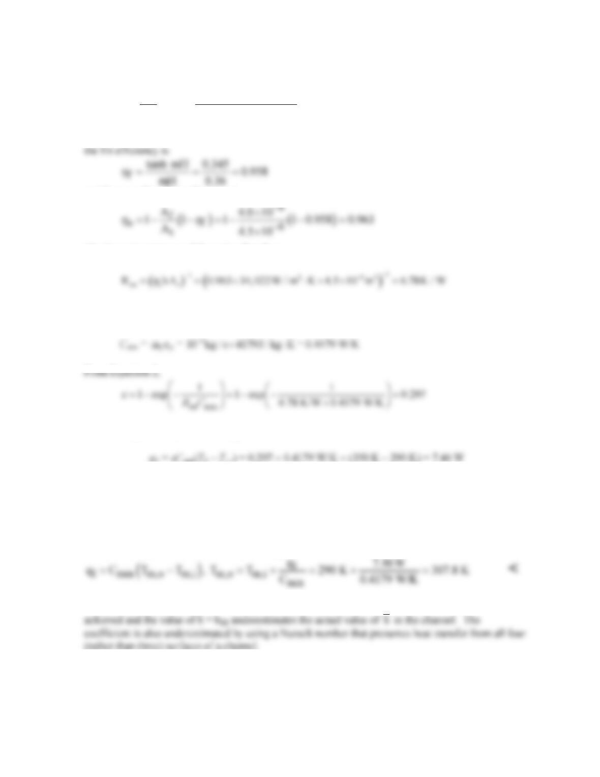
Determination of Rtot. The channel sidewalls act as fins, and a unit channel/sidewall combination is
shown in schematic (a), where the total number of unit cells corresponds to N = L/S. With N = 50
and L = 10 mm, S = 200
m
m and
δ
= S – W = 150
m
m. Alternatively, the unit cell may be represented
in terms of a single fin of thickness
δ
, as shown in schematic (b). The thermal resistance of the unit
PROBLEM 11.71 (Cont.)
2
D5
h
k 0.613W / m K 4.44
h Nu 34,022 W / m K
D8 10 m
−
⋅×
= = = ⋅
×
With m = (2h/kch
δ
)1/2 = (68,044 W/m2⋅K/140 W/m⋅K × 1.5 × 10⁻⁴m)1/2 = 1800 m-1 and mH = 0.36,
and the overall surface efficiency is
The thermal resistance of the unit cell is then
Determination of Cmin. The minimum heat capacity rate is
and from Equation 1, the heat rate per channel is
and the chip power dissipation is
l
q Nq 50 7.46 W 373 W==×=
<
The outlet temperature follows from an energy balance on a channel,
COMMENTS: (1) With L/Dh = 125 and (L/Dh)fd ≈ 0.05 ReD Pr = 273, fully developed flow is not
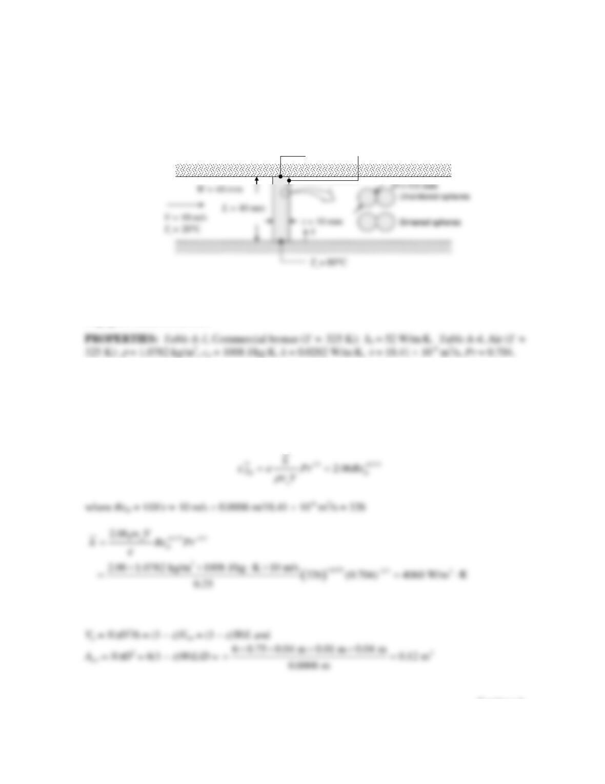
PROBLEM 11.72
KNOWN: Dimensions, particle diameter, and porosity of bronze foam sheet. Temperature of upper
and lower surfaces of foam. Velocity and inlet temperature of air flowing through foam.
FIND: Convection heat transfer rate to air accounting for both the increase in the air temperature as it
flows through the foam and thermal resistance due to conduction in the foam. Whether actual heat
transfer rate would be greater, less, or the same.
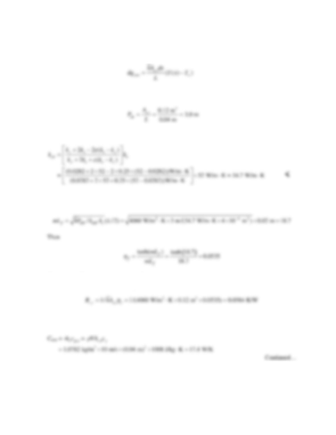
SCHEMATIC:
ASSUMPTIONS: (1) Steady–state conditions, (2) Constant properties, (3) Heat transfer coefficient
between foam and air can be determined from packed bed analysis, (4) Foam behaves as extended
surface, (5) Effective thermal conductivity of foam can be found from Maxwell’s relation, (6)
Negligible radiation transfer.
ANALYSIS: Following Example 11.7, the air flow can be treated as flow through a single stream
heat exchanger, exchanging heat with a surface at Ts through a single fin resistance. Due to symmetry,
the foam sheet can be treated as a fin of length L/2 with an insulated fin tip.
Because the fin is foam and the air flows through it, the heat transfer coefficient can be found from the
packed bed analysis of Equation 7.81:
The surface area of the sintered particles can be found as follows, where N = number of particles:
Continued…
T
s
= 80°C
ε
= 0.25
PROBLEM 11.72 (Cont.)
For a slice of the foam of length dx, the surface area of foam in contact with the air is dAs = Ap,tdx/L.
Thus,
By analogy with
conv ( () )dq hPdx T x T∞
= −
for a solid fin, we find
From Equation 3.25, with ks = kb,
The fin efficiency is given by Equation 11.4, where Ac is the fin cross–sectional area, Ac = Wt = 0.04 m
× 0.01 m = 4 × 10⁻⁴ m2. We first calculate
The fin is inefficient because it is significantly longer than it needs to be to maximize heat transfer
between the air and foam. From Equation 3.93, the fin resistance is
Note that the fin surface area is Ap,t, since this is the area for heat transfer between the foam and air.
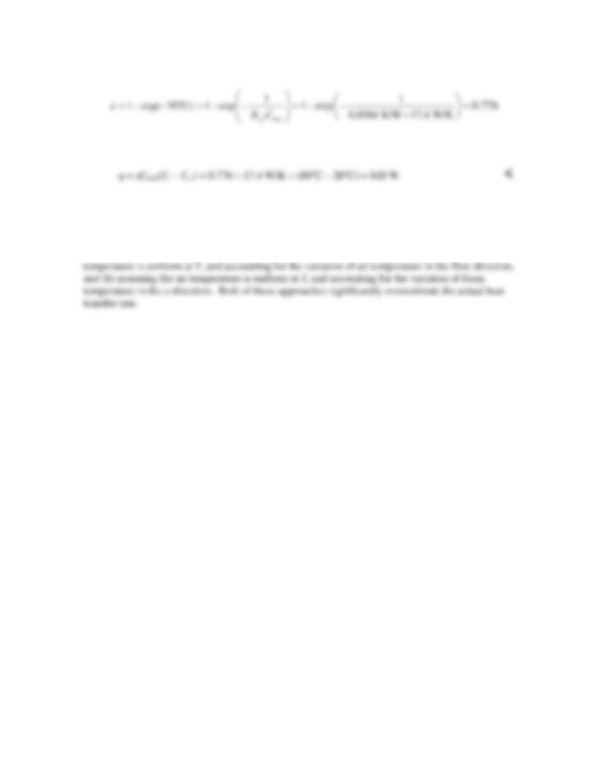
Following the approach in Example 11.7,
PROBLEM 11.72 (Cont.)
Finally,
This is probably close to the correct answer, although temperature gradients in the streamwise
direction in the foam are not accounted for. The actual value would therefore be less than 810 W. <
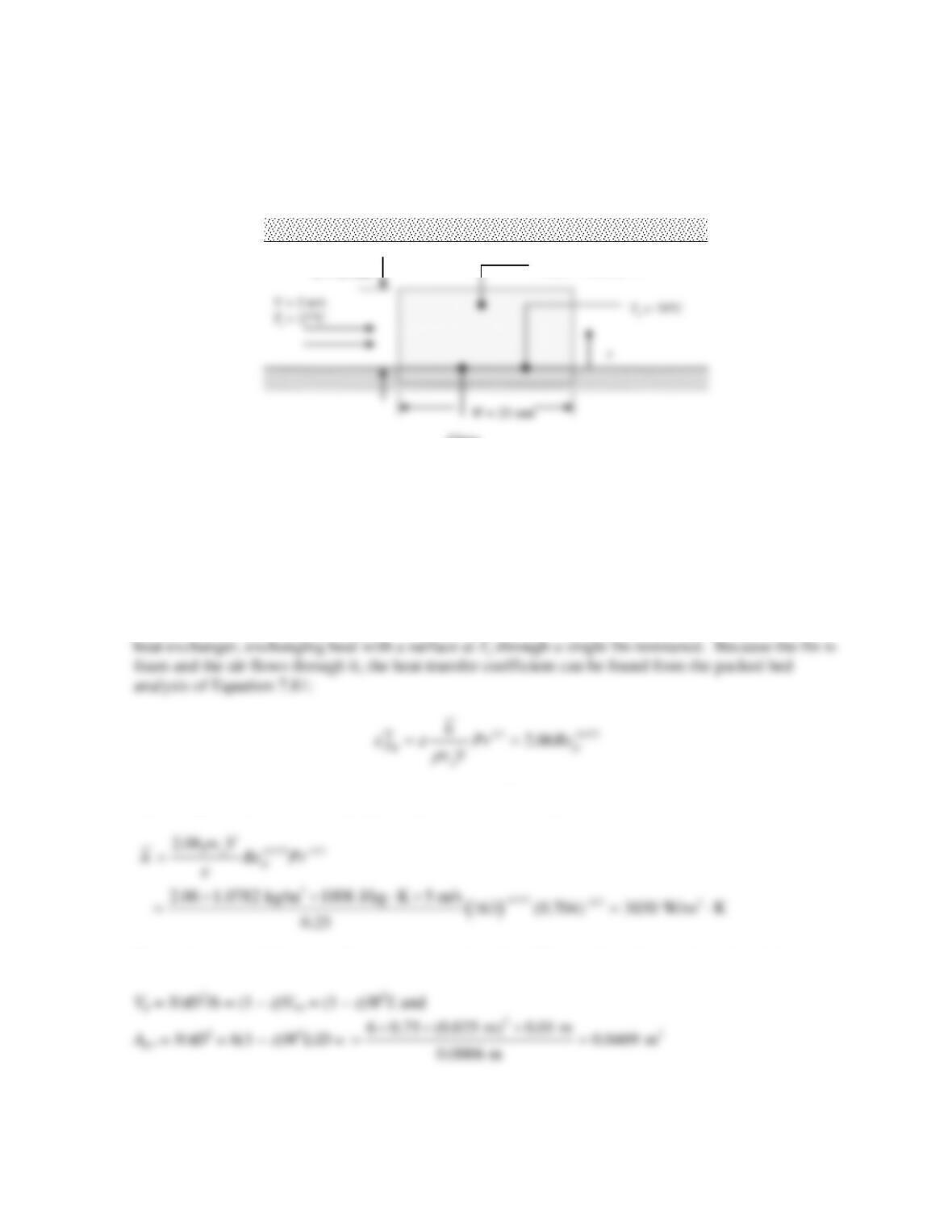
COMMENTS: The solution to Problem 7.90 was achieved in two ways: (a) assuming the foam
PROBLEM 11.73
KNOWN: Dimensions, particle diameter, and porosity of bronze foam heat sink attached to silicon
chip. Chip temperature. Velocity and inlet temperature of air flowing through foam.
FIND: Heat transfer rate from chip.
SCHEMATIC:
L = 10 mm
Chip
Foam heat sink
ASSUMPTIONS: (1) Steady–state, (2) Constant properties, (3) Heat transfer coefficient between
foam and air can be determined from packed bed analysis, (4) Foam behaves as extended surface, (5)
Effective thermal conductivity of foam can be found from Maxwell’s relation, (6) Air flows uniformly
through foam rather than being diverted toward open region above heat sink, (7) Negligible radiation
transfer.
PROPERTIES: Table A-1, Commercial bronze (T
≈
323 K): kb = 52 W/m⋅K. Table A-4, Air (T
≈
325 K):
r
a = 1.0782 kg/m3, cp,a = 1008 J/kg⋅K, ka = 0.0282 W/m⋅K,
ν
a = 18.41 × 10⁻⁶ m2/s, Pr = 0.704.
ANALYSIS: Following Example 11.7, the air flow can be treated as flow through a single stream
where ReD = VD/
ν
= 5 m/s × 0.0006 m/18.41 × 10–6 m2/s = 163
The surface area of the sintered particles can be found as follows, where N = number of particles:
Continued…
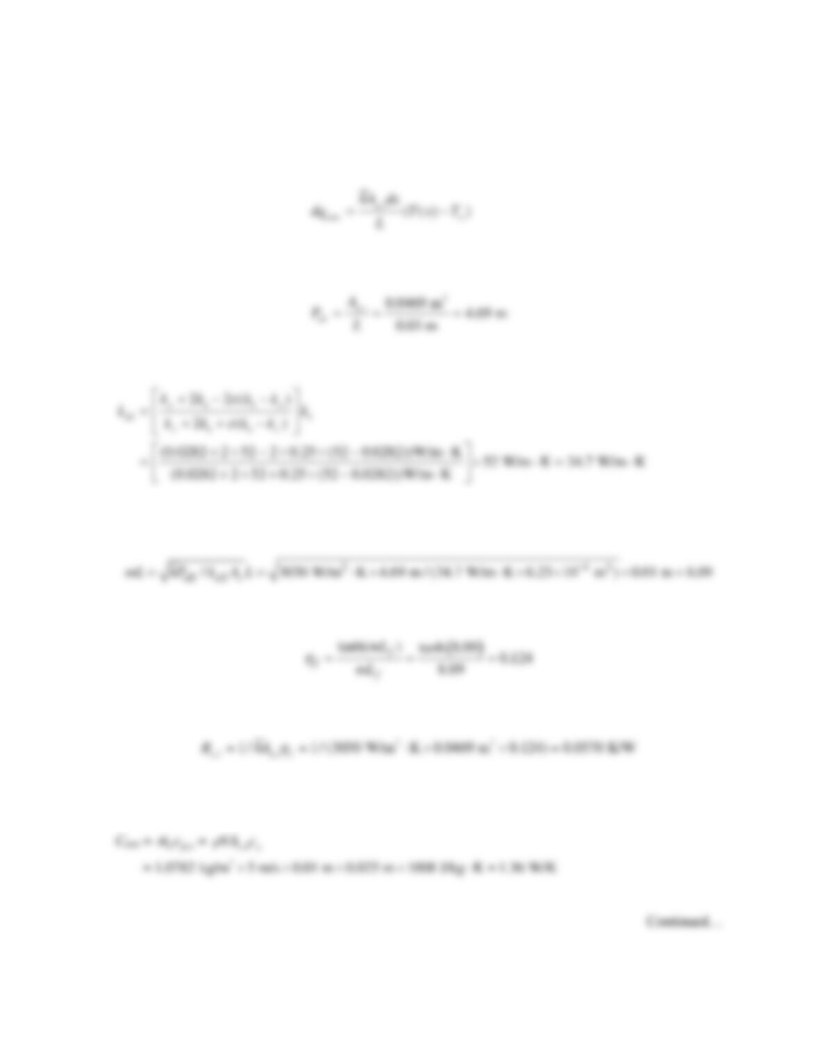
PROBLEM 11.73 (Cont.)
For a slice of the foam of length dx, the surface area of foam in contact with the air is dAs = Ap,tdx/L.
Thus,
By analogy with
conv ( () )dq hPdx T x T∞
= −
for a solid fin, we find
From Equation 3.25, with ks = kb,
The fin efficiency is given by Equation 11.4, where Ac is the fin cross–sectional area, Ac = W2 = (0.025
m)2 = 6.25 × 10⁻⁴ m2. We first calculate
Then
From Equation 3.93, the fin resistance is
Note that the fin surface area is Ap,t, since this is the area for heat transfer between the foam and air.
Following the approach in Example 11.7,
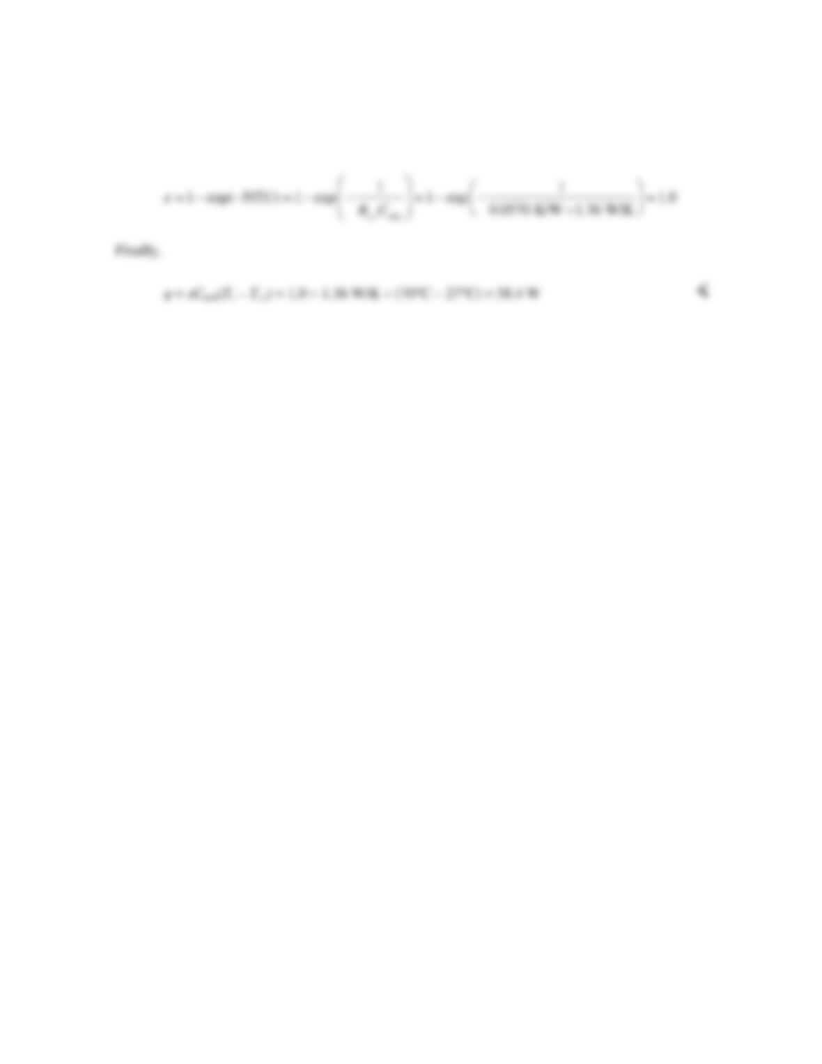
PROBLEM 11.73 (Cont.)
COMMENTS: (1) With a fin efficiency of unity, the foam temperature is essentially uniform at Ts,
and the heat transfer rate is identical to that which would be found from a packed bed analysis that
ignored the conduction resistance in the foam. This is an indication that the heat sink design could be
improved to reduce its weight without significantly sacrificing performance. (2) The heat sink poses a
resistance to air flow, and much of the air would be diverted around the foam block toward the open
area above it, reducing its performance. The design could be altered to inhibit diversion of the air to
the open region.
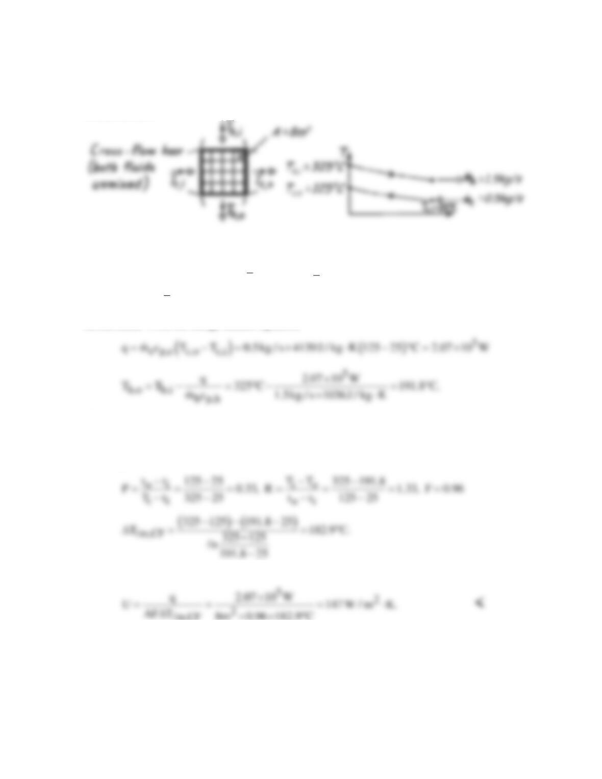
PROBLEM 11S.1
KNOWN: Operating conditions and surface area of a finned-tube, cross-flow exchanger.
FIND: Overall heat transfer coefficient.
SCHEMATIC:
ASSUMPTIONS: (1) Negligible heat loss to surroundings, (2) Constant properties, (3) Exhaust gas
properties are those of air.
PROPERTIES: Table A-6, Water
()
m
T75C:=° p
c 4139 J / kg K;=⋅ Table A-4, Air
()
m
T 255 C :š p
c 1036 J / kg K.=⋅
ANALYSIS: From the energy balance equations
Hence
mmm,CF
Uq/AT where T FT .=∆ ∆=∆
From Fig. 11S.3, with
Hence
m,CF
COMMENTS: From the
ε
– NTU method, Cc = 2069 W/K, Ch = 1554 W/K, (Cmin/Cmax) =0.751,
qmax = 4.66 × 10⁵ W and
ε
= 0.444. Hence, from Eq. 11.32, NTU ≈ 0.79 and U ≈ 150 W/m2⋅K.
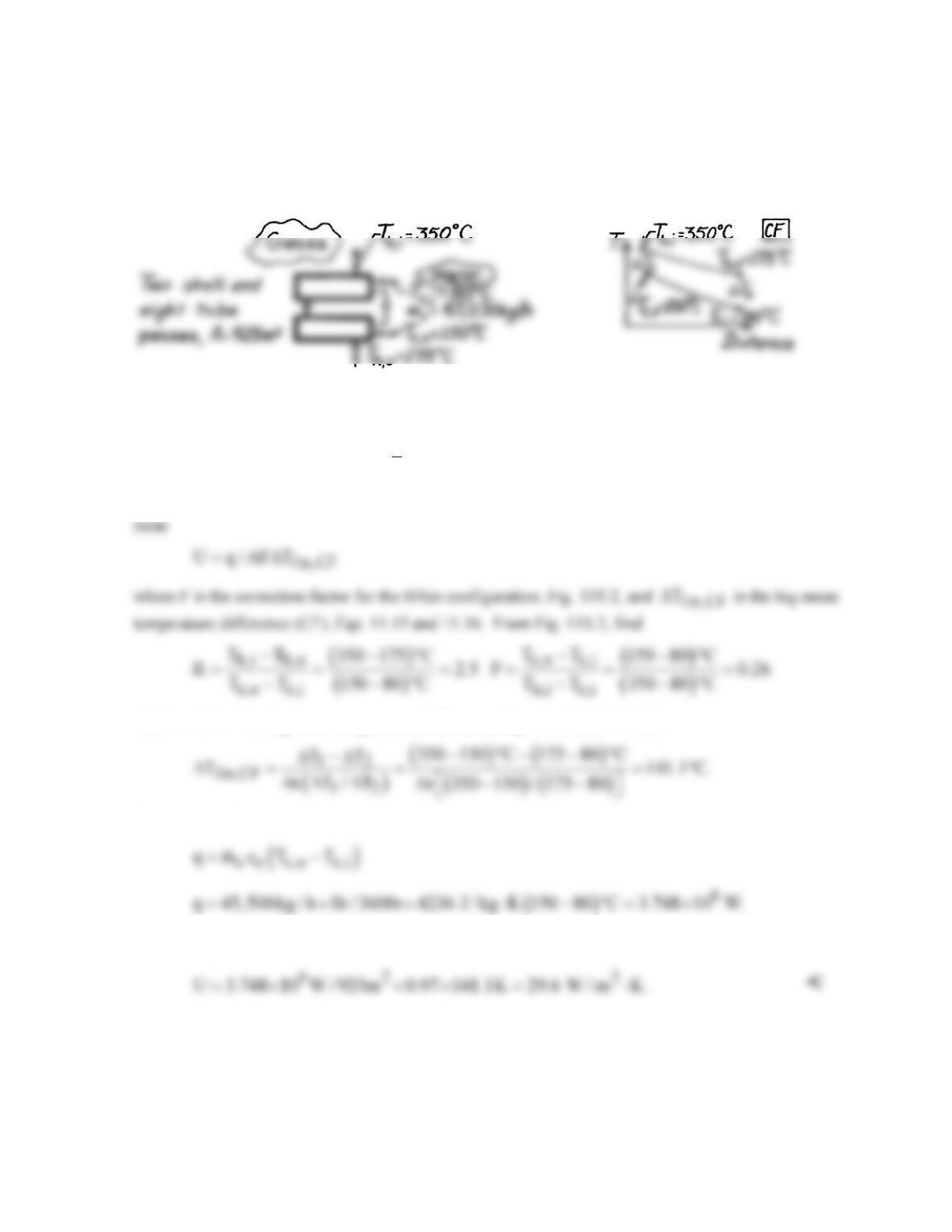
PROBLEM 11S.2
KNOWN: Heat exchanger with two shell passes and eight tube passes having an area 925m2; 45,500
kg/h water is heated from 80°C to 150°C; hot exhaust gases enter at 350°C and exit at 175°C.
FIND: Overall heat transfer coefficient.
SCHEMATIC:
ASSUMPTIONS: (1) Negligible losses to surroundings, (2) Negligible kinetic and potential energy
changes, (3) Constant properties, (4) Exhaust gas properties are approximated as those of atmospheric
air.
PROPERTIES: Table A-6, Water
( )
( )
c
T 80 150 C / 2 388K :=+°=
cc = cp,f = 4236 J/kg⋅K.
ANALYSIS: The overall heat transfer coefficient follows from Eqs. 11.9 and 11S.1 written in the
find F ≈ 0.97. The log-mean temperature difference, Eqs. 11.15 and 11.17, is
From an overall energy balance on the cold fluid (water), the heat rate is
Substituting values with A = 925 m2, find
COMMENTS: Compare the above result with representative values for air–water exchangers, as
given in Table 11.2. Note that in this exchanger, two shells with eight tube passes, the correction
factor effect is very small, since F = 0.97.
PROBLEM 11S.3
KNOWN: A shell and tube Hxer (two shells, four tube passes) heats 10,000 kg/h of pressurized
water from 35°C to 120°C with 5,000 kg/h water entering at 300°C.
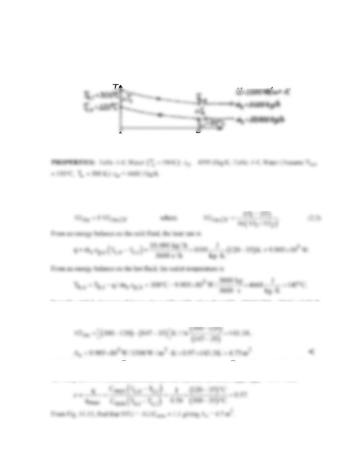
FIND: Required heat transfer area, As.
SCHEMATIC:
ASSUMPTIONS: (1) Negligible heat loss to surroundings, (2) Constant properties.
ANALYSIS: The rate equation, Eq. 11.14, can be written in the form
sm
A q/U T= ∆
(1)
and from Eq. 11S.1,
From Fig. 11S.2, determine F from values of P and R, where P = (120 – 35)°C/(300 – 35)°C = 0.32, R
= (300 – 147)°C/(120-35)°C = 1.8, and F ≈ 0.97. The log-mean temperature difference based upon a
CF arrangement follows from Eq. (3); find
COMMENTS: (1) Check
h
T
≈ 500 K used in property determination;
h
T
= (300 + 147)°C/2 = 497 K.
(2) Using the NTU-
ε
method, determine first the capacity rate ratio, Cmin /Cmax = 0.56. Then
PROBLEM 11S.4
KNOWN: The shell and tube Hxer (two shells, four tube passes) of Problem 11.14, known to have
an area 4.75m2, provides 95°C water at the cold outlet (rather than 120°C) after several years of
operation. Flow rates and inlet temperatures of the fluids remain the same.
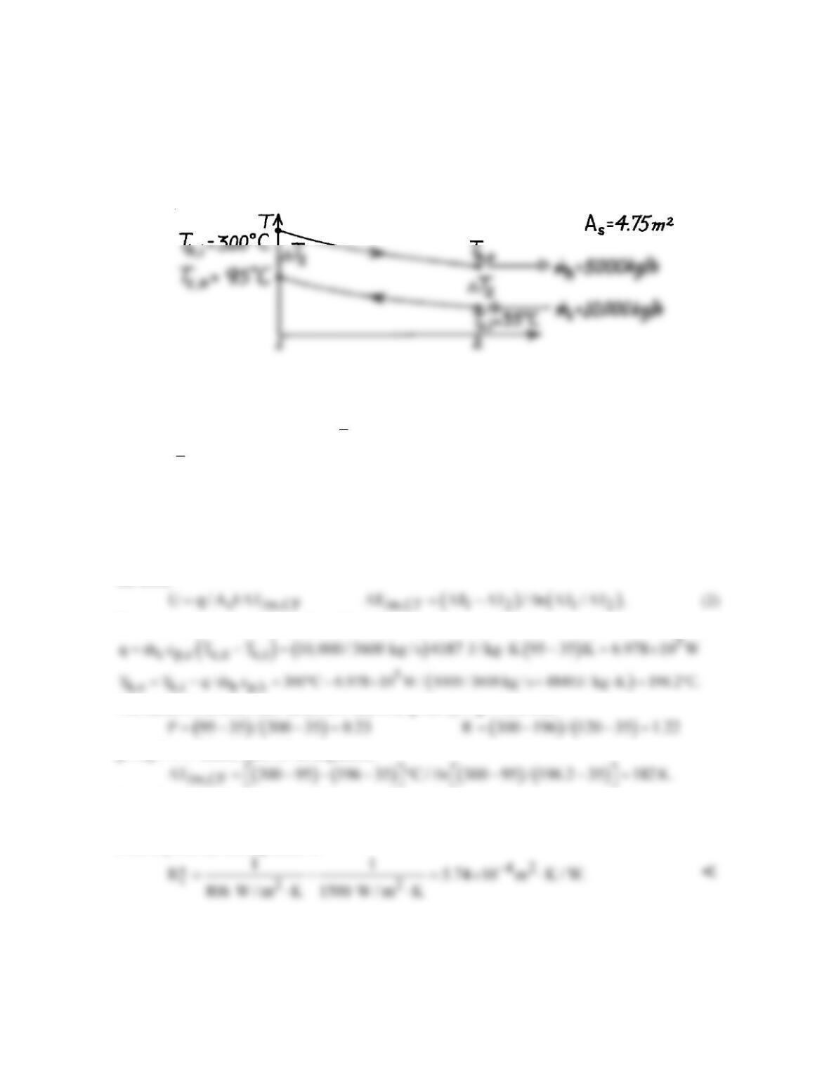
FIND: The fouling factor, Rf.
SCHEMATIC:
ASSUMPTIONS: (1) Negligible heat loss to surroundings, (2) Constant properties, (3) Thermal
resistance for the clean condition is
t
R′′
= (1500 W/m2⋅K)-1.
PROPERTIES: Table A-6, Water (
c
T
≈ 338 K): cp = 4187 J/kg⋅K; Table A-6, Water (Assume Th,o
≈ 190°C,
h
T
≈ 520 K): cp = 4840 J/kg⋅K.
ANALYSIS: The overall heat transfer coefficient can be expressed as
( )
tf f t
U 1/ R R or R 1/ U R
′′ ′′ ′′ ′′
=+=−
(1)
where
t
R′′
is the thermal resistance for the clean condition and
f
R′′
, the fouling factor, represents the
additional resistance due to fouling of the surface. The rate equation, Eq. 11.14 with Eq. 11S.1, has
the form,
From energy balances on the cold and hot fluids, find
The factor, F, follows from values of P and R as given by Fig. 11S.2 with
giving F ≈ 1. Based upon CF arrangement,
Using Eq. (2), find now the overall heat transfer coefficient as
52 2
U 6.978 10 W / 4.75m 1 182 K 806 W / m K.= × ×× = ⋅
From Eq. (1), the fouling factor is
COMMENTS: Note that the effect of fouling is to nearly double (Uclean/Ufouled = 1500/806 ≈ 1.9)
the resistance to heat transfer. Note also the assumption for Th,o used for property evaluation is
satisfactory.
PROBLEM 11S.5
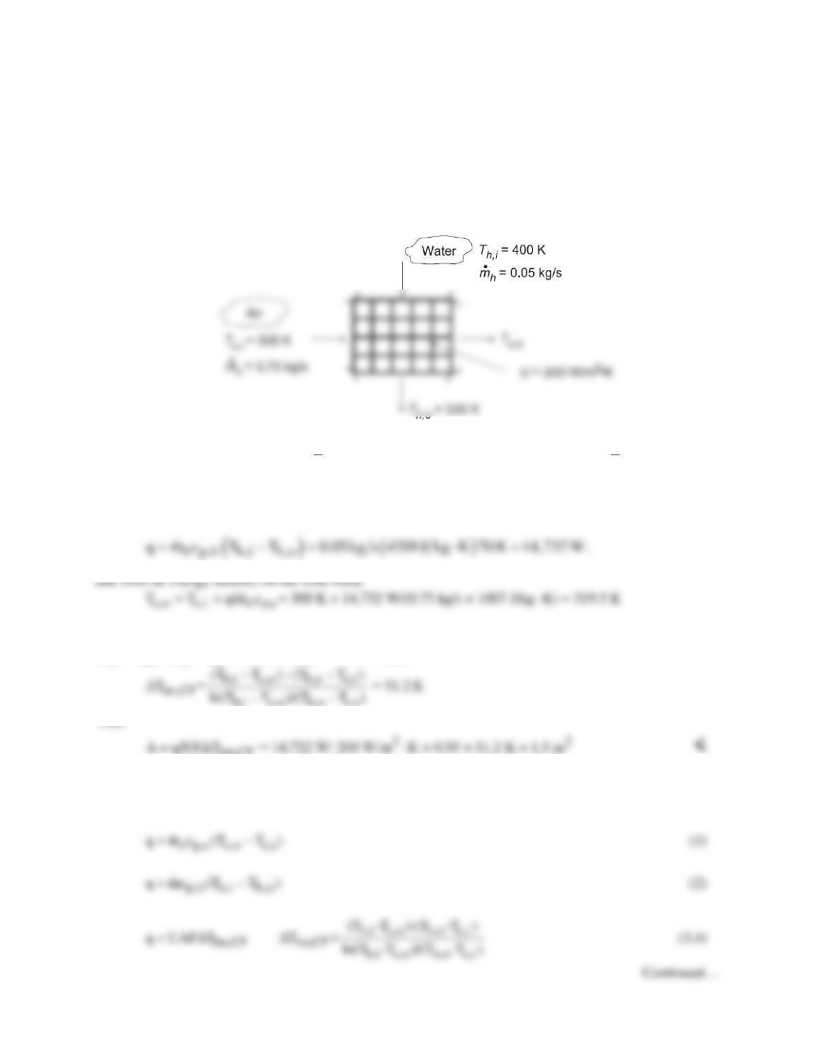
KNOWN: Flow rates and inlet temperatures for automobile radiator configured as a cross–flow heat
exchanger with both fluids unmixed. Overall heat transfer coefficient.
FIND: (a) Area required to achieve hot fluid (water) outlet temperature, Tm,o = 330 K, and (b) Outlet
temperatures, Th,o and Tc,o, as a function of the overall coefficient for the range, 200 ≤ U ≤ 400 W/m2⋅K
with the surface area A found in part (a) with all other heat transfer conditions remaining the same as for
part (a).
SCHEMATIC:
ASSUMPTIONS: (1) Negligible heat loss to surrounding, (2) Constant properties.
PROPERTIES: Table A.6, Water (
h
T
= 365 K): cp,h = 4209 J/kg⋅K; Table A.4, Air
( )
c
T 310 K≈
: cp,c
= 1007 J/kg⋅K.
ANALYSIS: (a) The required heat transfer rate is
We will use Eq. 11.14 with Eq. 11S.1. From Fig. 11S.3, with P = (Tc,o – Tc,i) / (Th,i – Tc,i) = 0.20 and R =
(Th,i – Th,o)/ (Tc,o – Tc,i) = 3.6, we find F ≈ 0.95. Then,
1m,CF
(b) To solve this “performance” problem using the log mean temperature difference method is very
cumbersome. It requires solving the following equations for the two unknown outlet temperatures (and
q), where F is also a function of the two outlet temperatures,
PROBLEM 11S.5 (Cont.)
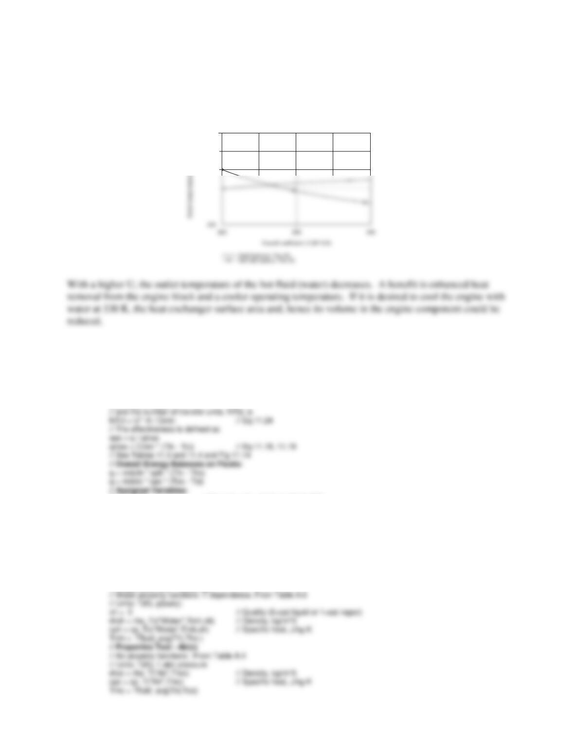
One rational approach is to work backward. For a specified value of q, Eqs. (1) and (2) can be used to
solve for the outlet temperatures. Then F and ∆Tlm,CF can be determined, and U can be found from Eq.
(3). In this way, we can generate the following plot.
350
COMMENT: This problem is much easier to solve using the ε–NTU method, as shown in this IHT
model.
// Heat Exchanger Tool – Cross–flow with both fluids unmixed:
// For the cross–flow, single–pass heat exchanger with both fluids unmixed,
eps = 1 – exp((1 / Cr) * (NTU^0.22) * (exp(–Cr * NTU^0.78) – 1)) // Eq 11.32
// where the heat–capacity ratio is
Cr = Cmin / Cmax
Cmin = Ch // Capacity rate, minimum fluid, W/K
Ch = mdoth * cph // Capacity rate, hot fluid, W/K
mdoth = 0.05 // Flow rate, hot fluid, kg/s
Thi = 400 // Inlet temperature, hot fluid, K
Tho = 330 // Outlet temperature, hot fluid, K; specified for part (a)
Cmax = Cc // Capacity rate, maximum fluid, W/K
Cc = mdotc * cpc // Capacity rate, cold fluid, W/K
mdotc = 0.75 // Flow rate, cold fluid, kg/s
Tci = 300 // Inlet temperature, cold fluid, K
U = 200 // Overall coefficient, W/m^2.K
// Properties Tool – Water (h)