Problem 11.30
The Pitot tube on a supersonic aircraft cruising at an altitude of 30,000 ft senses a
stagnation pressure of 12 psia . If the atmosphere is considered standard, determine the
airspeed and Mach number of the aircraft. A shock wave is present just upstream of the
probe impact hole.
Solution 11.30
At 30,000 ft , we read from the Standard Atmosphere table
Thus,
Thus,
Problem 11.31
An aircraft cruises at a Mach number of 2.0 at an altitude of 15 km. Inlet air is decelerated
to a Mach number of 0.4 at the engine compressor inlet. A normal shock occurs in the inlet
diffuser upstream of the compressor inlet at a section where the Mach number is
1
.2. For
isentropic diffusion, except across the shock, and for standard atmosphere, determine the
stagnation temperature and pressure of the air entering the engine compressor.
Solution 11.31
The deceleration process in the inlet diffuser is assumed to be adiabatic since we are
considering isentropic diffusion except across the shock. Thus,
0
At 15km elevation in standard atmosphere, we find
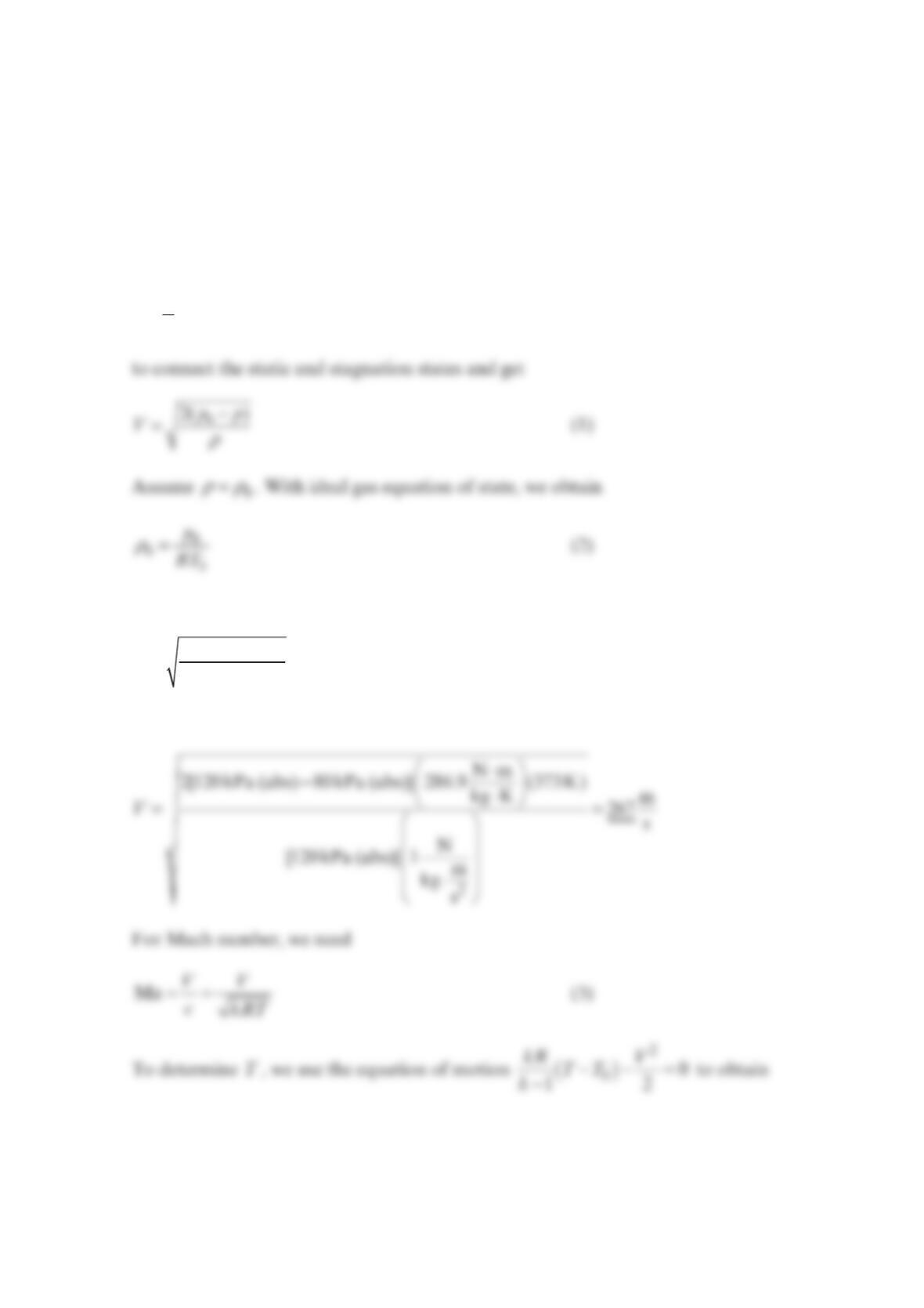
To determine the stagnation pressure at the compressor inlet, we use
Combining Eqs. (4) and (5), we obtain
For =Ma 1.2
x, we read from the Shock Table
Also, since the flow is isentropic except across the shock,
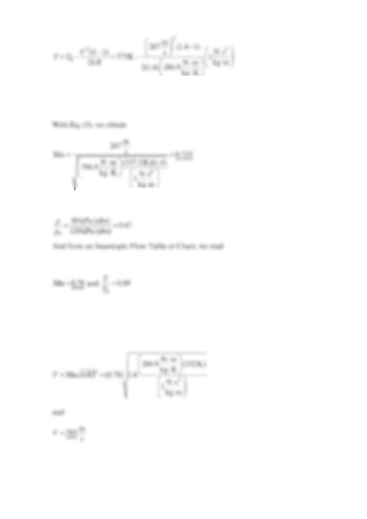
Thus, with Eq. (3), we obtain
To determine the static pressure at the compressor inlet, we use the Isentropic Flow with
Ma 0.4
comp inlet = and find
Problem 11.32
At some point for air flow in a duct, =20 psiap, =500 RT, and =500 ft/sV. Can a
normal shock occur at this point?
Solution 11.32
Flow must be supersonic to admit possibility of a normal shock. The Mach number is
Problem 11.33
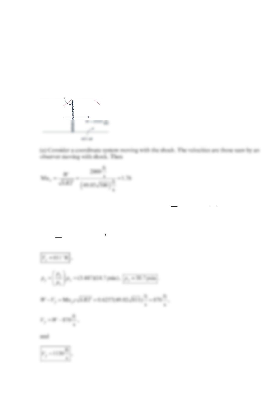
A normal shock propagates at 2000 ft/s into the still air in a tube. The temperature and
pressure of the air are 80 °F and 14.7 psia before “hit” by the shock. Calculate the air
temperature, pressure, and velocity after the shock, the stagnation temperature and
pressure relative to the shock ahead of and behind the shock, and the stagnation
temperature and pressure relative to the tube ahead of and behind the shock.
Solution 11.33
For =Ma 1.76
y, the Shock Table gives
M
a0.625
7
y=, =1.502
y
x
T
T, and 3.447
y
x
p
p=. (Then
(y) is to the left or behind the shock)
==
(1.502)(540 R)
y
yx
x
T
TT
T,
shock
T
y
,
P
y
,
Ma
y
T
x
,
P
x
,
Ma
x
(b) For
M
a1.76
x=, the Isentropic Flow Table gives =
0
0.185
p
p and
0
0.6175
T
T=.
Then
Problem 11.34
Air at =
1800 m/sV, =
1100 kPap, and =
1300 KT passes through a normal shock. Calculate
the velocity 2
V
, temperature 2
T
, and pressure 2
p
after the shock. What would be the values
of 2
T and 2
p
if the same velocity change were accomplished isentropically?
Solution 11.34
Use Normal Shock and Isentropic Flow Tables or Charts
Then
and
The energy equation for isentropic flow of an ideal gas gives
or =586 K
y
T
Since the flow is isentropic
Problem 11.35
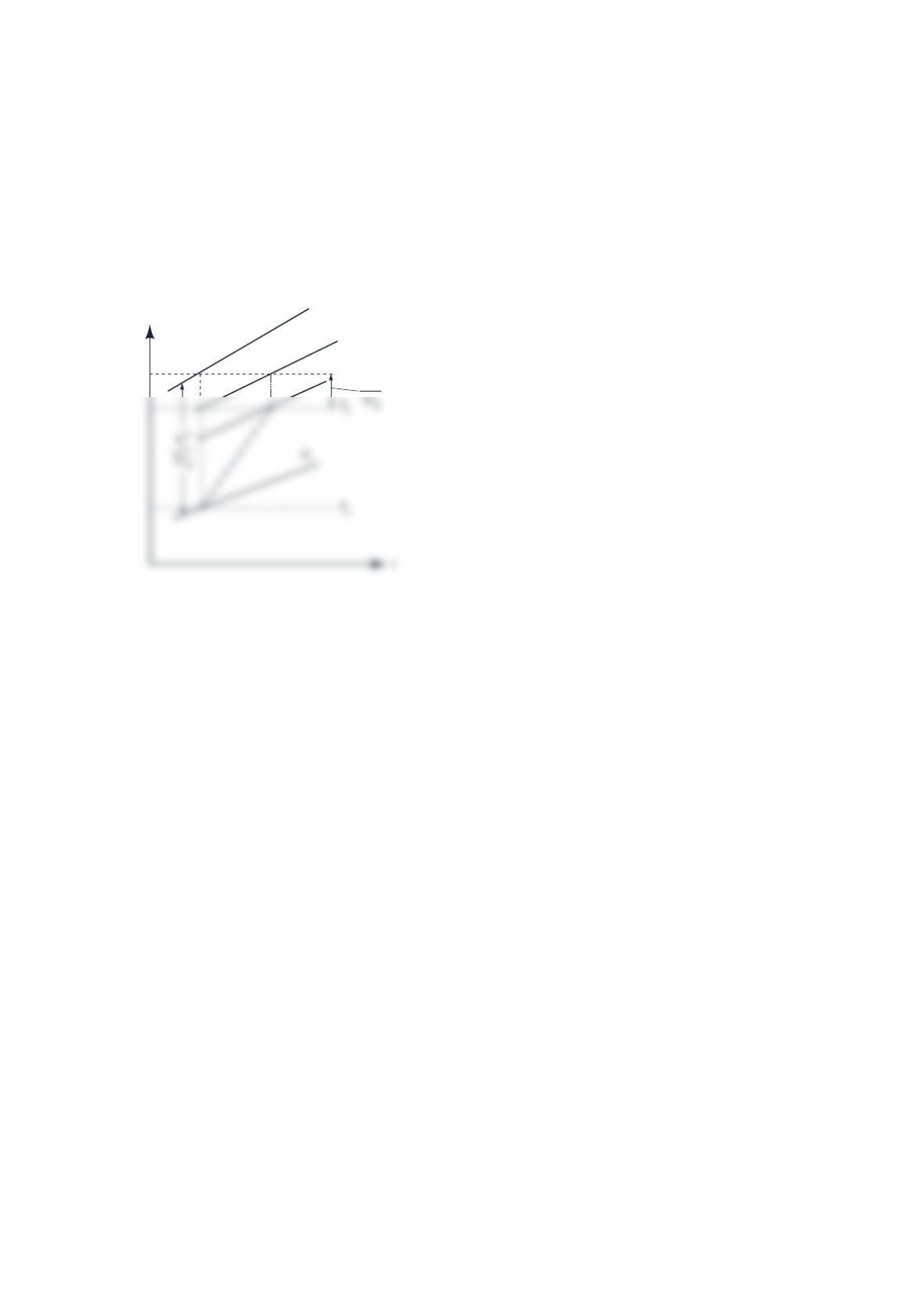
A normal shock occurs in a perfect gas. Sketch a Temperature–Entropy (T–s) diagram of
the process and show the following: Static and stagnation pressure and temperature before
and after the shock and gas velocity before and after the shock.
Solution 11.35
T
p
0
x
T
0
p
0
y
p
y
V
y
2
Problem 11.36
The stagnation pressure and temperature of air flowing past a probe are 120 kPa (abs) and
100 °C, respectively. The air pressure is 80 kPa (abs) . Determine the airspeed and the Mach
number considering the flow to be (a) incompressible and (b) compressible.
Solution 11.36
(a) Assuming incompressible flow, we use Bernoulli’s equation
ργ
++=
2
1constant along streamline
2
pVz
and combining Eqs. (1) and (2), we obtain
−
=00
0
2( )
p
pRT
Vp
or
p
or
=337.5KT
(b) For compressible flow,
and thus
=(0.89)(373K)=332KT
Thus,
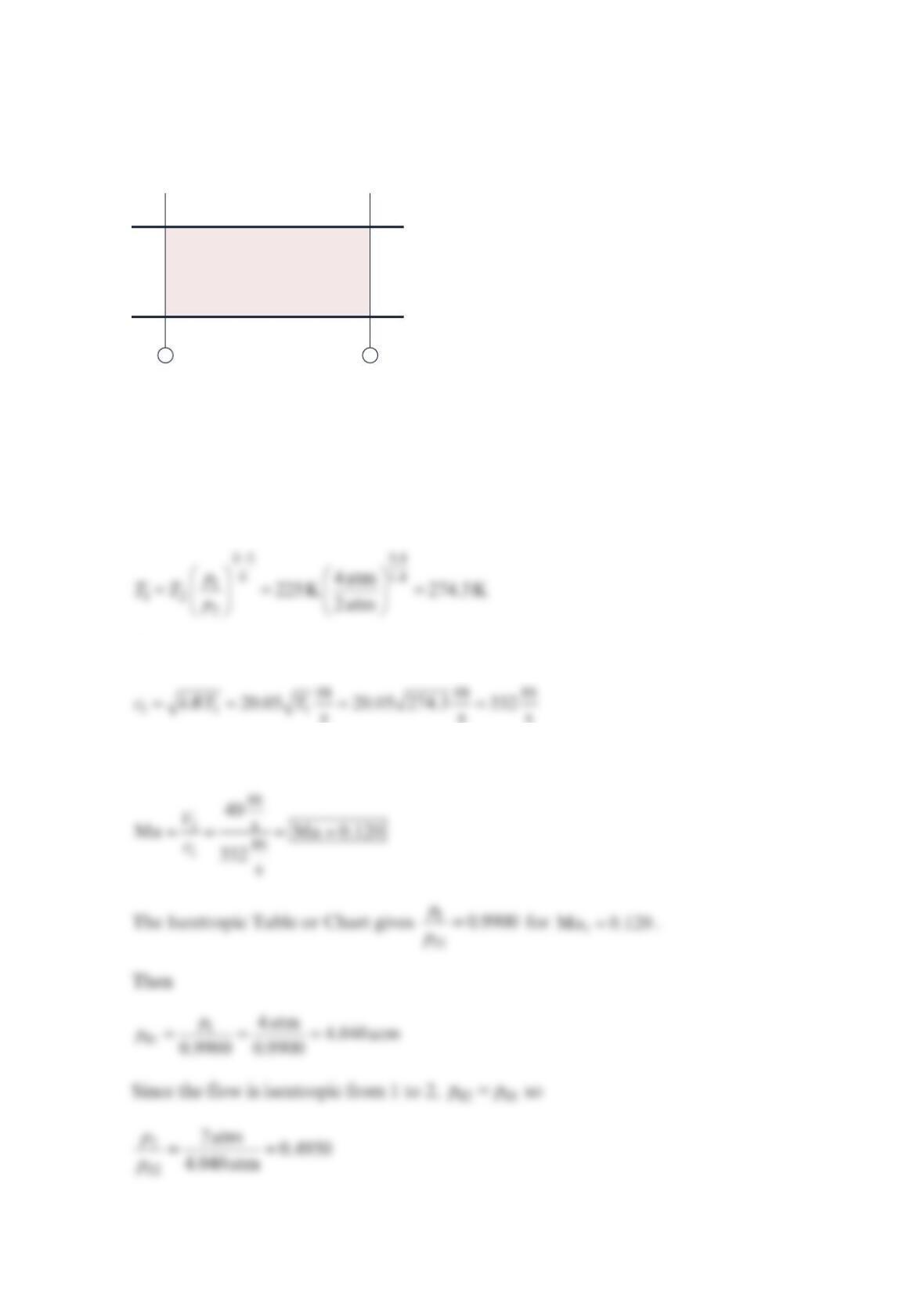
Problem 11.37
Air flows isentropically through a duct as shown in the figure below. For the conditions
shown, find the Mach number at both stations 1 and 2 and the flowrate. The diameter is
not necessarily constant.
Solution 11.37
The temperature 1
T is found from
Then
sss
and
D1
= 0.15 m
V1
= 40 m/s
p
1
= 4 atm abs.
T2
= 225 K
p2
= 2 atm abs.
12
Ma
1
Ma
2
The Isentropic Table or Chart gives =
2
Ma 1.055
The ideal gas law gives
Problem 11.38
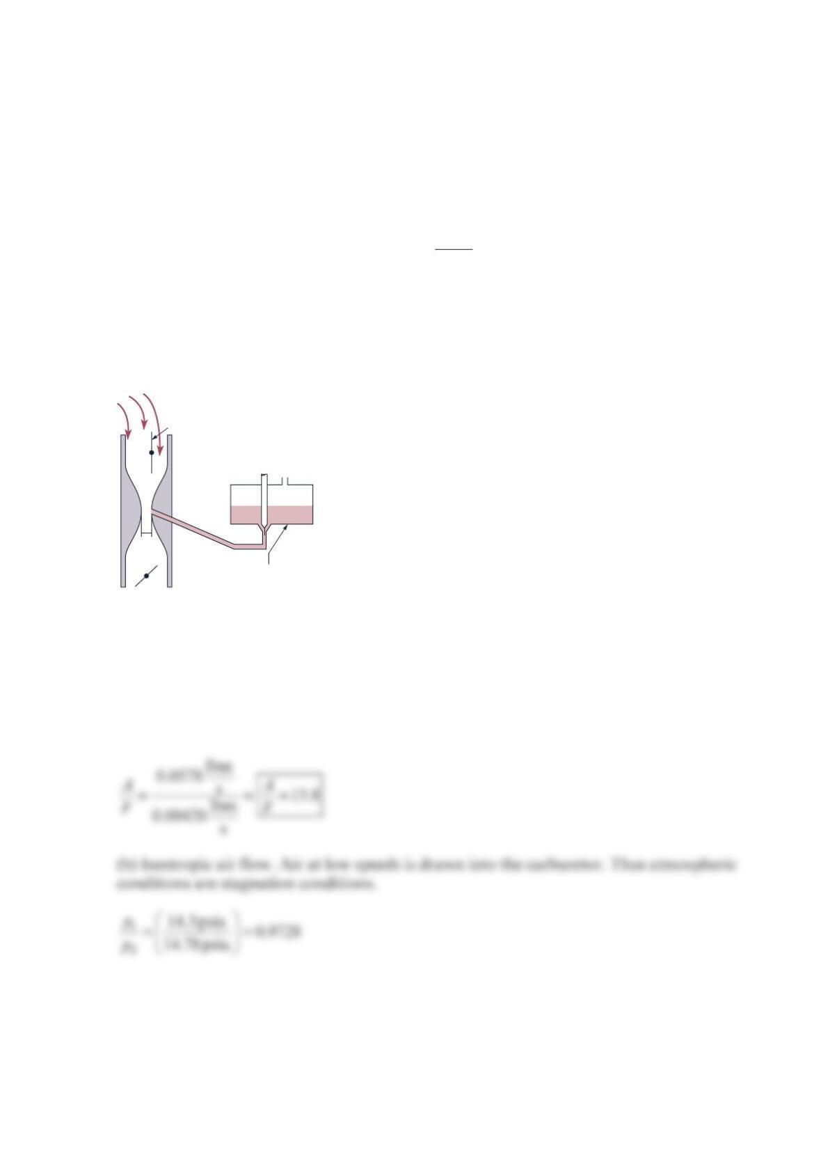
A simplified schematic diagram of a carburetor of a gasoline engine is shown in the figure
below. The throat area is 2
0.5 in. . The engine draws air downward through the carburetor
Venturi and maintains a throat pressure of 14.3 psia . This low throat pressure draws fuel
from the float chamber and into the air stream. The energy losses in the 0.06-in.I.D. fuel
line and valve are given by
=
2
2
L
KV
hg,
with =6.0K. The fuel specific gravity is 0.75 . Assume an atmospheric pressure of
14.7 psia . Find the air–fuel ratio (i.e., the ratio of the air mass flowrate to the fuel mass
flowrate) based on an (a) ideal (constant density and inviscid) air flow and (b) an isentropic
air flow.
Solution 11.38
(a) The case of the constant density and inviscid air flow wad solved as Problem 5.96. The
air flowrate was calculated to be 0.0578lbm/s and the fuel flowrate was calculated to be
0.00420 lbm/s . The air/fuel ratio is
Air
vent
Choke
Air
0.5
in2
Throttle
Float chamber
Fuel
The Isentropic Table or Chart gives =Ma 0.1989
t and =
0
0.9922
t
T
T so
and
=lbm
0.0575 s
air
m.
Assume that the fuel is incompressible. The incompressible energy equation for the fuel line
becomes
or
γρ
−−
==
++
2( ) 2( )
(1 ) (1 )
ch t ch t
t
f
f
gp p p p
Vkk
.
The numerical values give
The air/flowratio is
==
lbm
0.0575 s
lbm
0.00420 s
air
fuel
m
A
Fm or =13.70
A
F
Problem 11.39
An engineering student wants to satisfy her curiosity about the compressibility of air in
motion. She has set up a converging nozzle in which air discharges into the atmosphere.
The figure below shows the nozzle with the necessary information. For these conditions,
find the velocity at the exit by using the incompressible Bernoulli’s equation, a compressible
isothermal process, and a compressible isentropic process. Comment on your results.
Solution 11.39
(a) Incompressible Bernoulli equation, for zero elevation changes,
Using the stagnation density in the tank,
(b) For a compressible, isothermal process, using themomentum equation and ideal gas law
gives
p
0 = 175 kPa
T
0 = 300 K
V
0 ≈ 0
0 = 2.04 kg/m3
V
1
T
b = 300 K
p
b = 100 kPa
b = 1.16 kg/m3
ρ
ρ
Since =
00V,
(c) For a compressible, isentropic process ,
==
1
0
100 kPa 0.5714
175kPa
p
p
Comment:
Bernoulli Lowest estimate
Compressible,
Medium estimate
Problem 11.40
A nozzle for a supersonic wind tunnel is designed to achieve a Mach number of
3
.0, with a
velocity of 2000 m/s, and a density of 1.0 kg/m3 in the test section. Find the temperature and
pressure in the test section and the upstream stagnation conditions. The fluid is helium.
Solution 11.40
==
Ma
e
ee
e
V
ckRT ,
=
2
Ma
e
e
e
V
TkR ,
The exit pressure is found using the ideal gas law.
test section
pressure
Using
Using
Problem 11.41
Air flows isentropically through a duct to a section where =
125kPap, =
1300 KT, and
=
1900 m sV. For these conditions:
(a) Determine the stagnation conditions for the flow.
(b) What is the Mach number at station 1? Show a −Ts
diagram displaying
stagnation and static conditions.
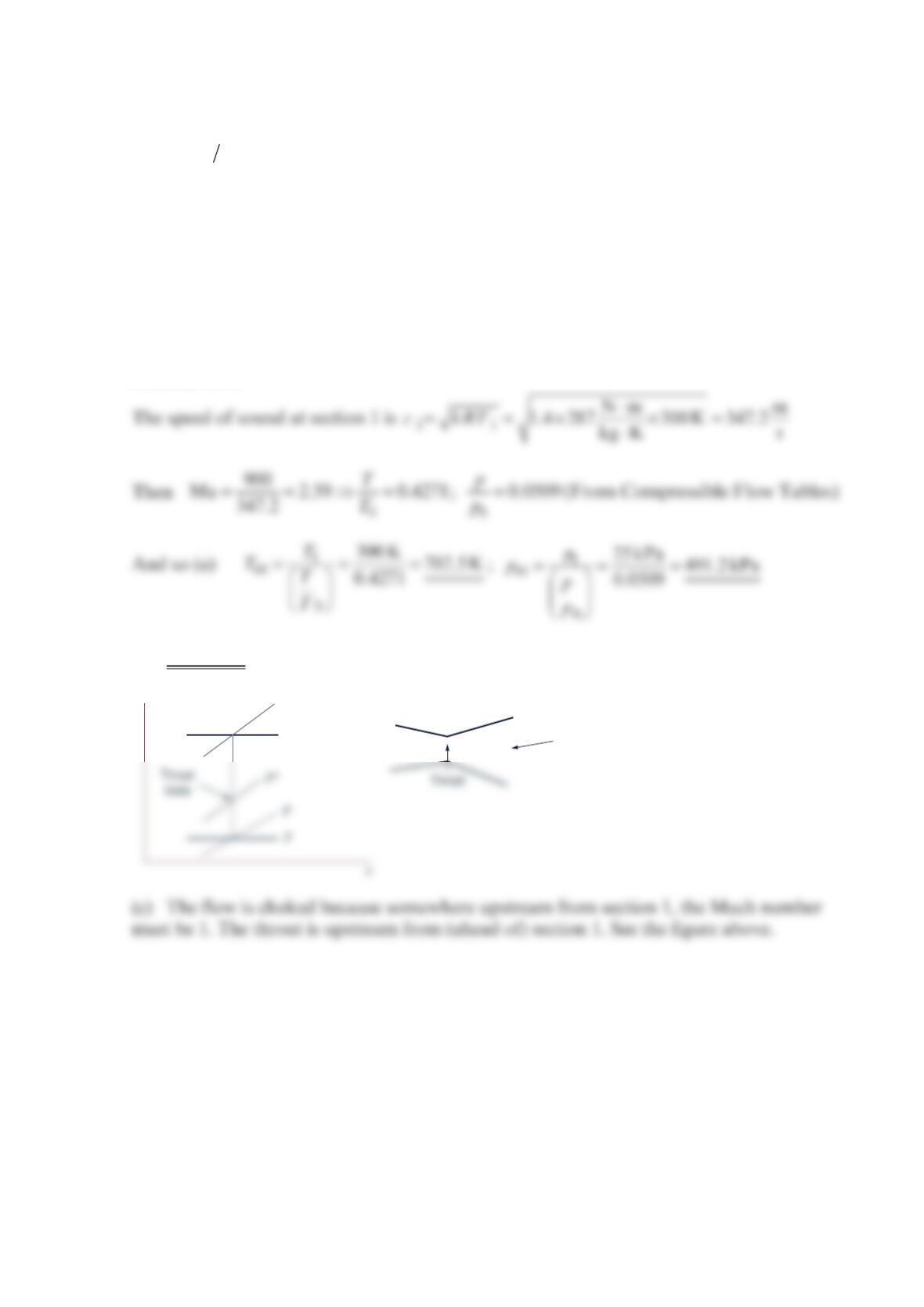
(c) Is the flow choked? Is the throat behind or ahead of section 1? Label this
state on the −Ts
diagram.
Solution 11.41
(b) =Ma 2.59
Section 1
p
0
T
0
T