PROBLEM 11.23
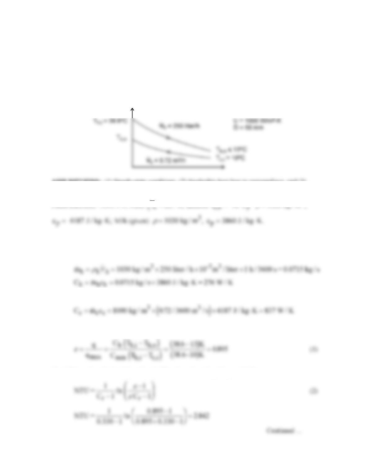
KNOWN: Cooling milk from a dairy operation to a safe-to–store temperature, Th,o ≤ 13°C, using
ground water in a counterflow concentric tube heat exchanger with a 50-mm diameter inner pipe and
overall heat transfer coefficient of 1000 W/m2⋅K.
FIND: (a) The UA product required for the chilling process and the length L of the exchanger, (b)
The outlet temperature of the ground water, and (c) the milk outlet temperatures for the cases when
the water flow rate is halved and doubled, using the UA product found in part (a)
SCHEMATIC:
T
ASSUMPTIONS: (1) Steady-state conditions, (2) Negligible heat loss to surroundings, and (3)
Constant properties.
PROPERTIES: Table A-6, Water
T K, assume T 18 C
= =287 a
ρ
=1000 kg / m
3
,
ANALYSIS: (a) Using the effectiveness–NTU method, determine the capacity rates and the
minimum fluid.
Hot fluid, milk:
Cold fluid, water:
It follows that Cmin = Ch. The effectiveness of the exchanger from Eq. 11.20 is
The NTU can be calculated from Eq. 11.29b, where Cr = Cmin/Cmax = 0.330,
PROBLEM 11.23 (Cont.)
From Eq. 11.24, find UA
and the exchanger tube length with A = π DL is
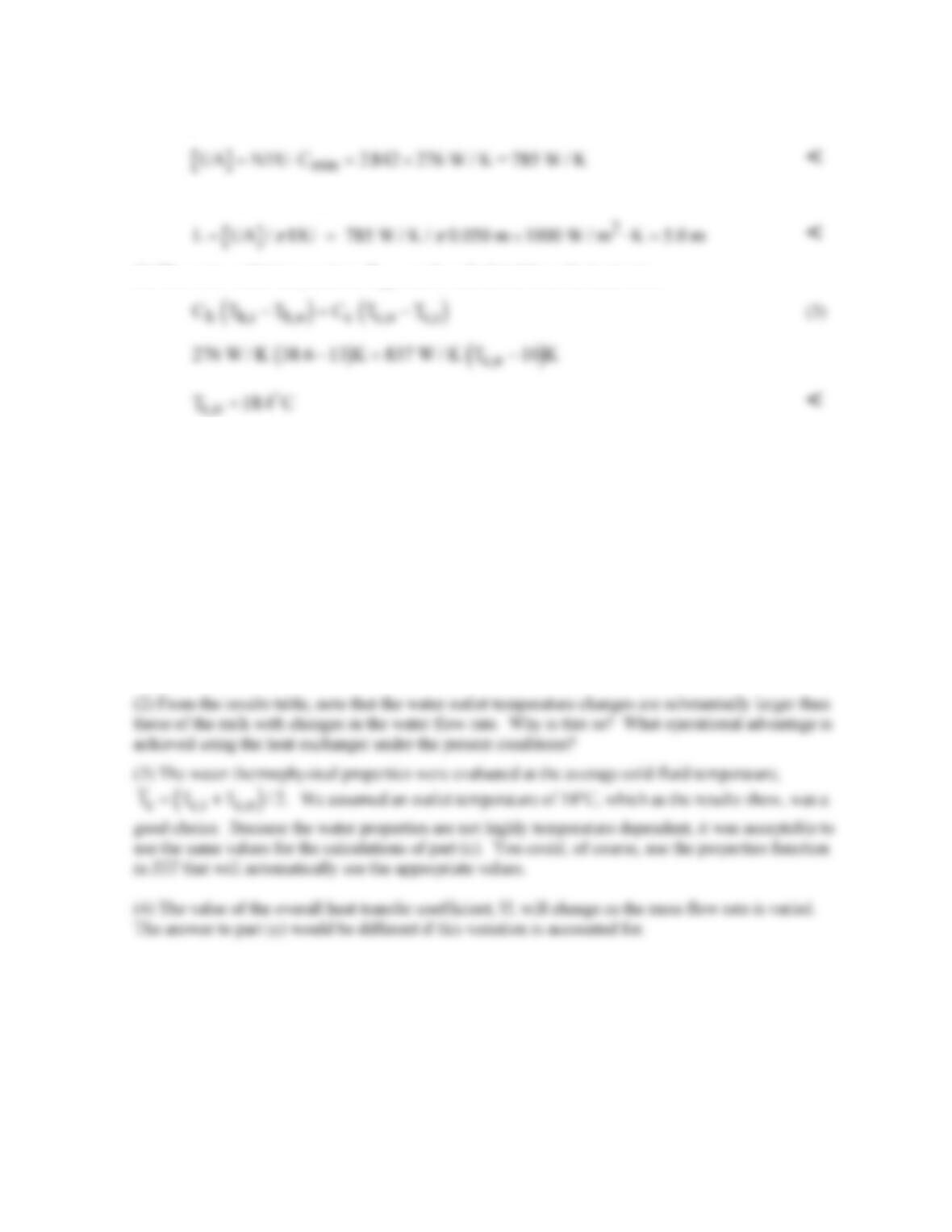
(b) The water outlet temperature, Tc,o, can be calculated from the heat rates,
(c) Using the foregoing Eqs. (1 – 3) in the IHT workspace, the hot fluid (milk) outlet temperatures are
evaluated with UA = 785 W/K for different water flow rates. The results, including the hot fluid
outlet temperatures, are compared to the base case, part (a).
Case Cc (W/K) Tc,o (
°
C) Th,o (
°
C)
1, halved flow rate 419 14.9 25.6
Base, part (a) 837 13 18.4
2, doubled flow rate 1675 12.3 14.3
COMMENTS: (1) From the results table in part (c), note that if the water flow rate is halved, the
milk will not be properly chilled, since Tc,o = 14.9°C > 13°C. Doubling the water flow rate reduces
the outlet milk temperature by less than 1°C.
PROBLEM 11.24
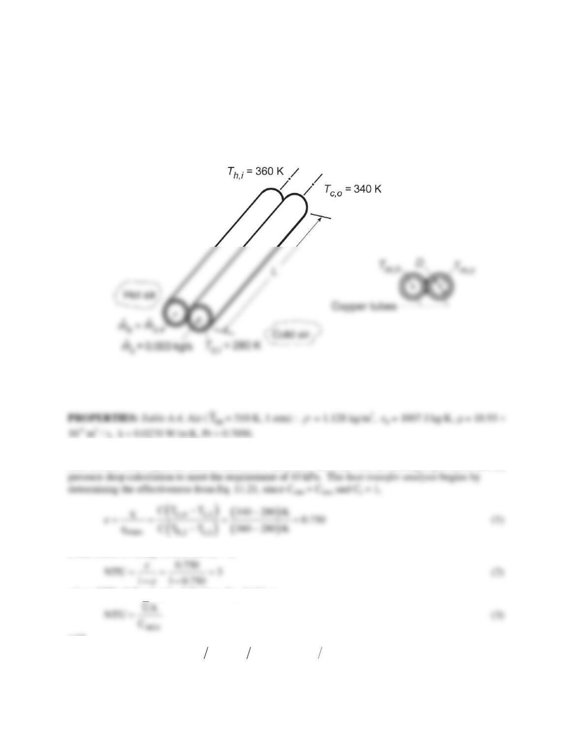
KNOWN: Twin-tube counterflow heat exchanger with balanced flow rates,
m
= 0.003 kg/s. Cold
airstream enters at 280 K and must be heated to 340 K. Maximum allowable pressure drop of cold
airstream is 10 kPa.
FIND: (a) Tube diameter D and length L which satisfies the heat transfer and pressure drop
requirements, and (b) Compute and plot the cold stream outlet temperature Tc,o, the heat rate q, and
pressure drop Dp as a function of the balanced flow rate from 0.002 to 0.004 kg/s.
SCHEMATIC:
ASSUMPTIONS: (1) Steady-state conditions, (2) Negligible heat loss to surroundings, (3) Average
pressure of the airstreams is 1 atm, (4) Tube walls act as fins with 100% efficiency, (4) Fully developed
flow.
ANALYSIS: (a) The heat exchanger diameter D and length L can be specified through two analyses: (1)
heat transfer based upon the effectiveness–NTU method to meet the cold air heating requirement and (2)
From Table 11.4, Eq. 11.29b for Cr = 1,
where NTU, following its definition, Eq. 11.24, is
with
min p
C mc 0.003kg s 1007 J kg K 3.021K W= = × ⋅=
(4)
Continued…
PROBLEM 11.24 (Cont.)
and 1 UA represents the thermal resistance between the two fluids at Tm,h and Tm,c as illustrated in the
above-right schematic. Since the tube walls are isothermal, it follows that
ch
1 UA 1 h A 1 h A= +
(5)
and since the flow conditions are nearly identical
ch
hh
= so that
where the heat transfer area is
This is a consequence of the assumption that the walls act as fins with 100% efficiency. Hence, Eq. (3)
can now be expressed as
Assuming an average mean temperature
m,c
T 310 K=
, characterize the flow with
and assuming the flow is both turbulent and fully developed using the Dittus–Boelter, Eq. 8.60,
Note that the heating condition has been selected (n = 0.4) for both streams, as an estimate.
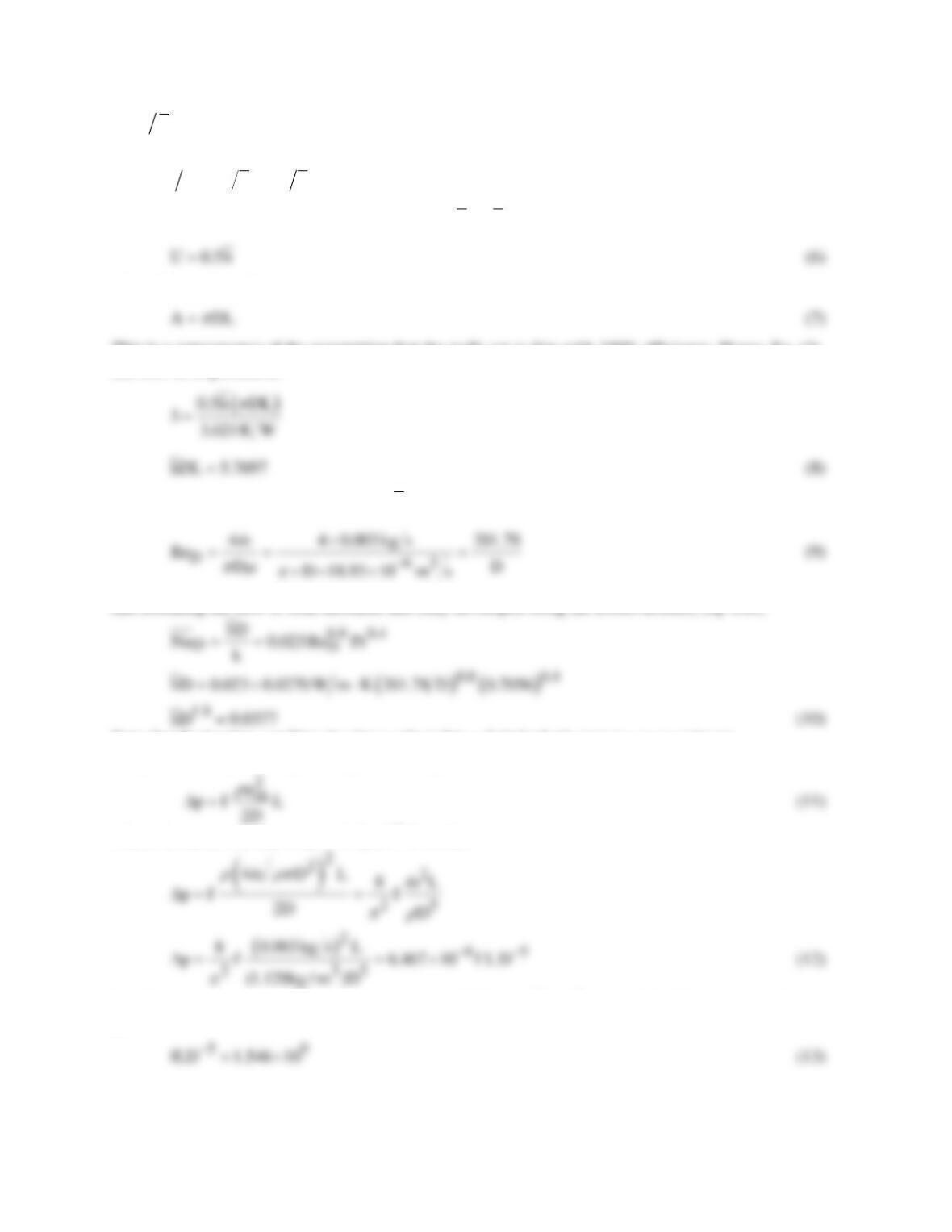
The pressure drop for fully developed flow, Eq. 8.22a, is
where the mean velocity is um =
m
/(ρπD2/4) so that
Recall that the pressure drop requirement is Dp = 10 kPa = 104 N/m2 , so that Eq. (12) can be rewritten
as
Continued…
PROBLEM 11.24 (Cont.)
For the Reynolds number range, 3000 ≤ ReD ≤ 5 ×10⁶ , Eq. 8.21 provides an estimate for the friction
factor,
In the foregoing analysis, there are 4 unknowns (D, L, f,
h
) and 4 equations (8, 10, 13, 14). Using the
IHT workspace, find
For this configuration, ReD = 22,500 so the flow is turbulent and since L/D = 3.5/0.0090 = 390 >> 10, the
fully developed assumption is reasonable.
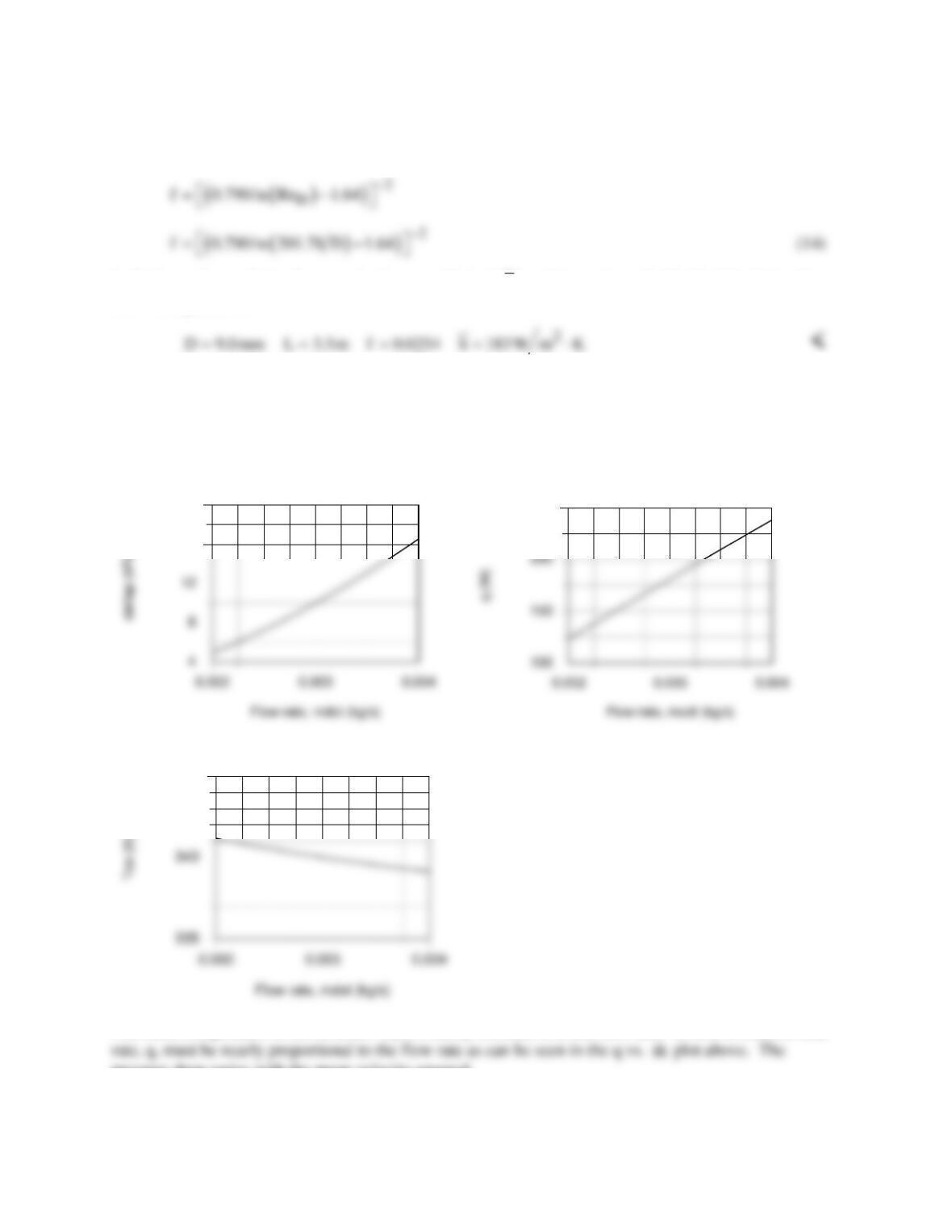
(b) The foregoing analysis entered into the IHT workspace was used to determine Tc,o , q and Dp as a
function of the balanced flow rate,
m
.
16
20
250
345
The outlet temperature of the cold air, Tc,o , is nearly insensitive to the flow rate. It follows that the heat
pressure drop varies with the mean velocity squared.
PROBLEM 11.25
KNOWN: Single pass, cross–flow heat exchanger with hot exhaust gases (mixed) to heat water
(unmixed)
FIND: Required surface area.
SCHEMATIC:
ASSUMPTIONS: (1) Negligible heat loss to surroundings, (2) Exhaust gas properties assumed to be
those of air.
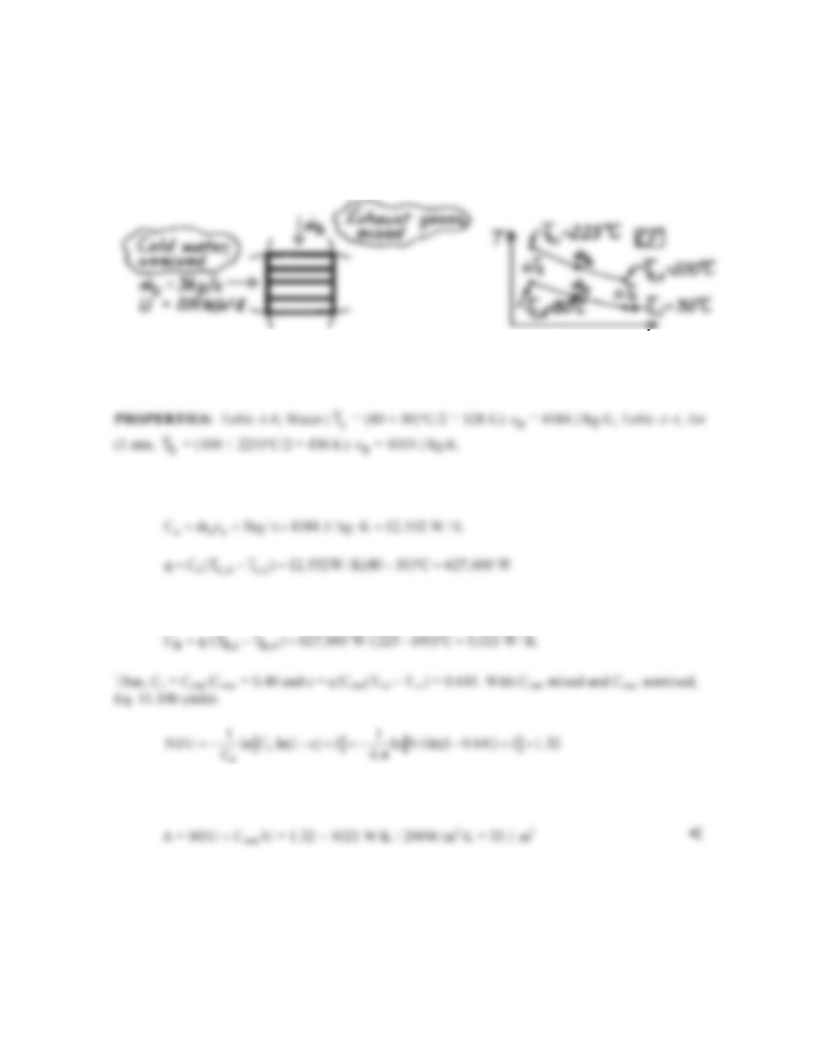
ANALYSIS: Using the e-NTU method,
From an energy balance on the hot fluid,
Thus,
PROBLEM 11.26
KNOWN: Heat exchanger in car operating between warm radiator fluid and cooler outside air.
Effectiveness of heater is
0.25
air
~m
e
−
since water flow rate is large compared to that of the air. For
low-speed fan condition, heater warms outdoor air from –10°C to 30°C.
FIND: (a) Increase in heat added to car for high-speed fan condition causing
air
m
to be doubled
while inlet temperatures remain the same, and (b) Air outlet temperature for medium–speed fan
condition where air flow rate increases 50%.
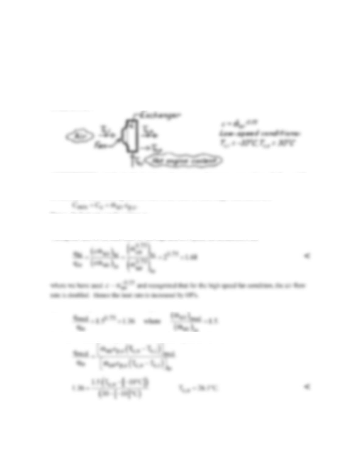
SCHEMATIC:
ASSUMPTIONS: (1) Negligible heat losses from heat exchanger to surroundings, (2) Th,i and Tc,i
remain fixed for all fan–speed conditions, (3) Water flow rate is much larger than that of air.
ANALYSIS: (a) Assuming the flow rate of the water is much larger than that of air,
Hence, the heat rate can be written as
( ) ( )
max min h,i c,i air p,air h,i c,i
qq C TT mc TT.
ee e
= = −=⋅ −
Taking the ratio of the heat rates for the high and low speed fan conditions, find
(b) Considering the medium and low speed conditions, it was observed that,
To find the outlet air temperature for the medium speed condition,
PROBLEM 11.27
KNOWN: Counterflow heat exchanger formed by two brazed tubes with prescribed hot and cold
fluid inlet temperatures and flow rates.
FIND: Outlet temperature of the air.
ASSUMPTIONS: (1) Negligible loss/gain from tubes to surroundings, (2) Flow in tubes is fully
developed since L/Dh = 40 m/0.030m = 1333.
PROPERTIES: Table A-6, Water (
h
T
= 335 K): ch = cp,h = 4186 J/kg⋅K, µ = 453 × 10-6 N⋅s/m2, k
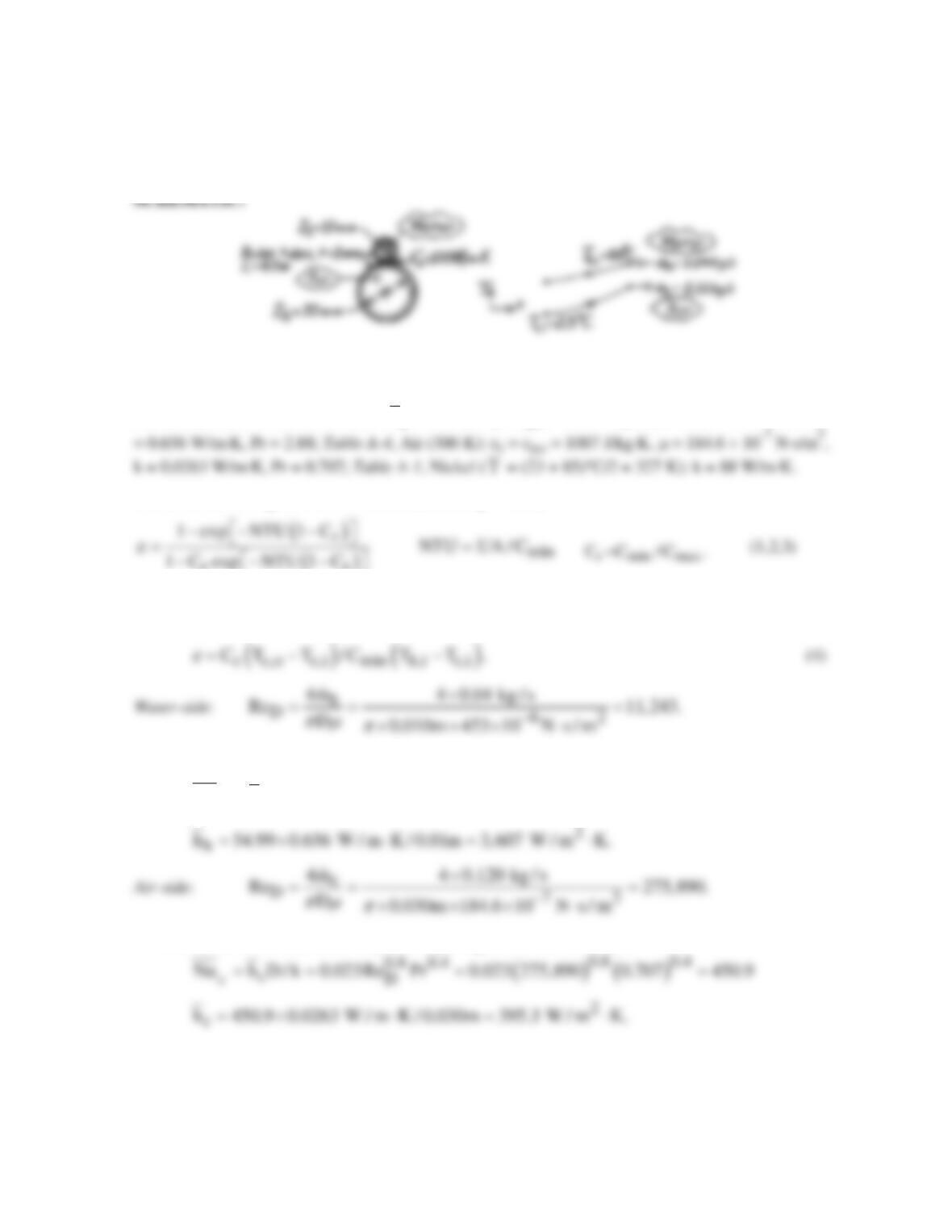
ANALYSIS: Using the NTU – e method, from Eq. 11.29a,
rr
Estimate UA from a model of the tubes and flows, and determine the outlet temperature from the
expression
The flow is turbulent and since fully developed, use the Dittus-Boelter correlation,
( ) ( )
h
0.8 0.3
0.8 0.3
hD
Nu h D / k 0.023Re Pr 0.023 11, 243 2.88 54.99= = = =
The flow is turbulent and since fully developed, again use the correlation
Overall coefficient: From Eq. 11.1, considering the temperature effectiveness of the tube walls and
the thermal conductance across the brazed region,
Continued …
PROBLEM 11.27 (Cont.)
hc
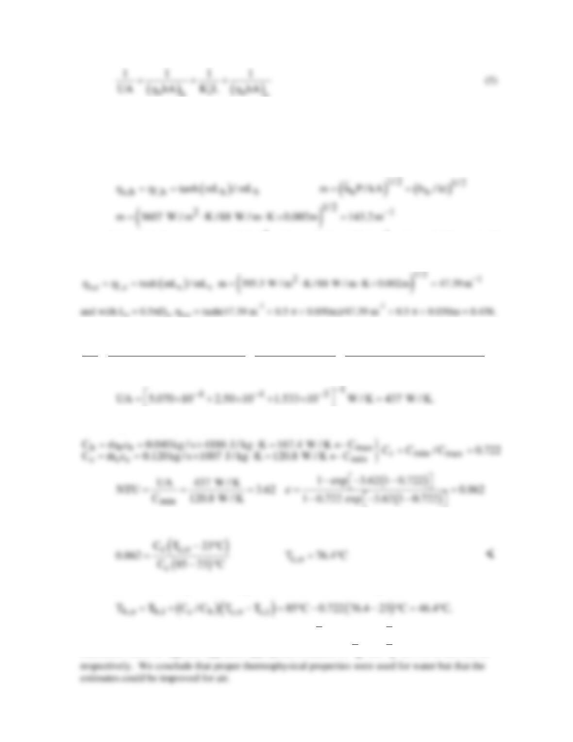
where ho needs to be evaluated for each of the tubes. Note that each tube can be viewed as two fins of
length πD/2. However, since the fins exchange heat on only one side, they can be combined into a
single fin of length πD/2 and thickness 2t, exchanging heat on both sides.
Water–side temperature effectiveness:
( )
2
hh
A D L 0.010m 40m 1.257 m
ππ
= = =
and with Lh = 0.5 πDh, ho,h = tanh(143.2 m-1 × 0.5 π × 0.010m)/143.2 m-1 × 0.5 π × 0.010 m = 0.435.
Air–side temperature effectiveness: Ac = πDcL = π(0.030m)40m = 3.770 m2
Hence, the overall heat transfer coefficient using Eq. (5) is
( )
22 22
11 1 1
UA 100 W / m K 40m
0.435 3607 W / m K 1.257 m 0.438 395.3 W / m K 3.770 m
= ++
⋅
× ⋅× × ⋅×
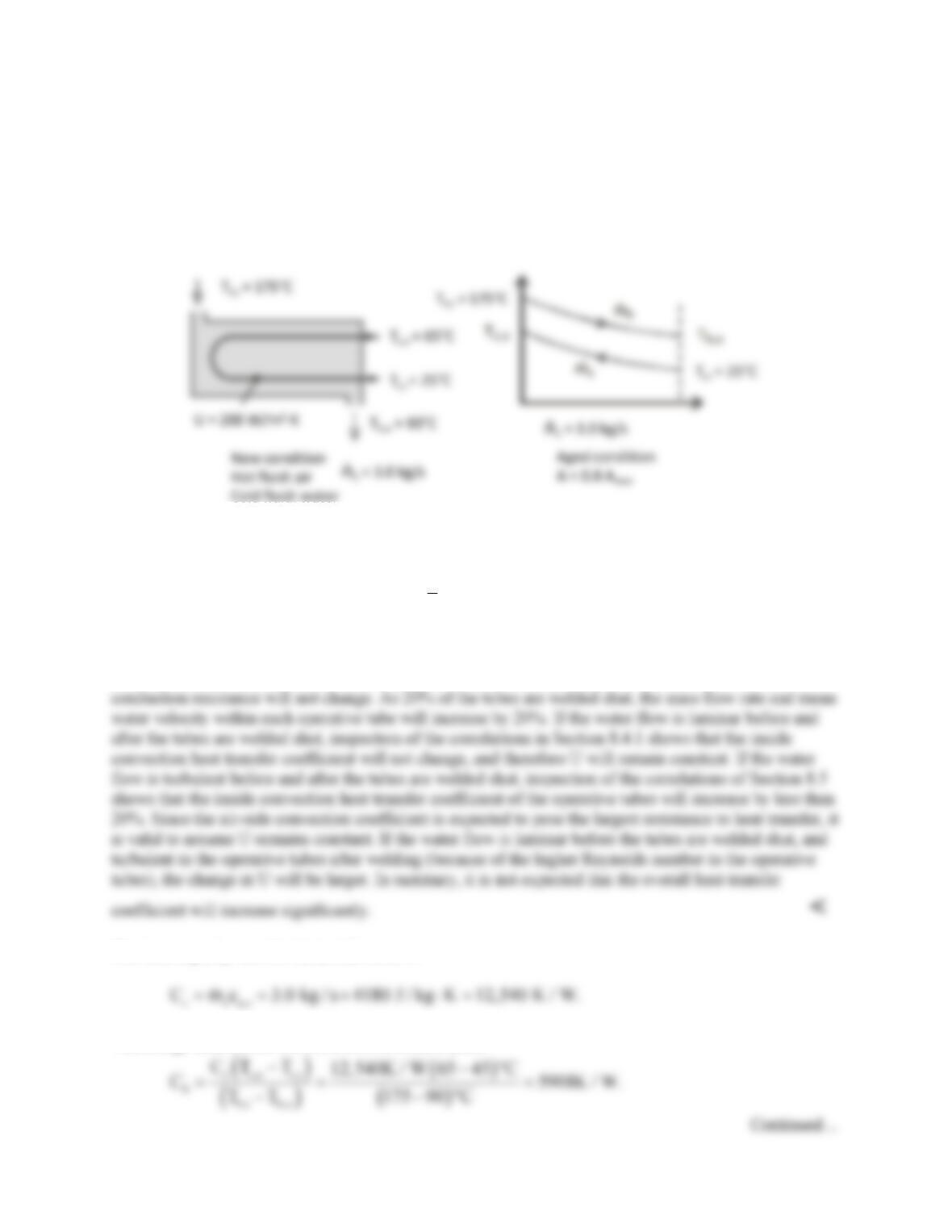
Evaluating now the heat exchanger effectiveness from Eq. (1) with
and finally from Eq. (4) with Cmin = Cc,
COMMENTS: (1) Using overall energy balances, the water outlet temperature is
(2) To initially evaluate the properties, we assumed that
h
T
≈ 335 K and
c
T
≈ 300 K. From the
calculated values of Th,o and Tc,o, more appropriate estimates of
T
and
T
are 338 K and 322 K,
PROBLEM 11.28
KNOWN: Shell-and-tube heat exchanger with one shell and two tube passes. Liquid water flow rate,
inlet and outlet design conditions. Air inlet temperature and air outlet temperature when new. Initial
(new) value of the overall heat transfer coefficient. Percentage of tubes taken out of operation over time.
FIND: Would overall heat transfer coefficient change significantly as tubes are taken out of service?
Exit water temperature after 20% of tubes are taken out of service.
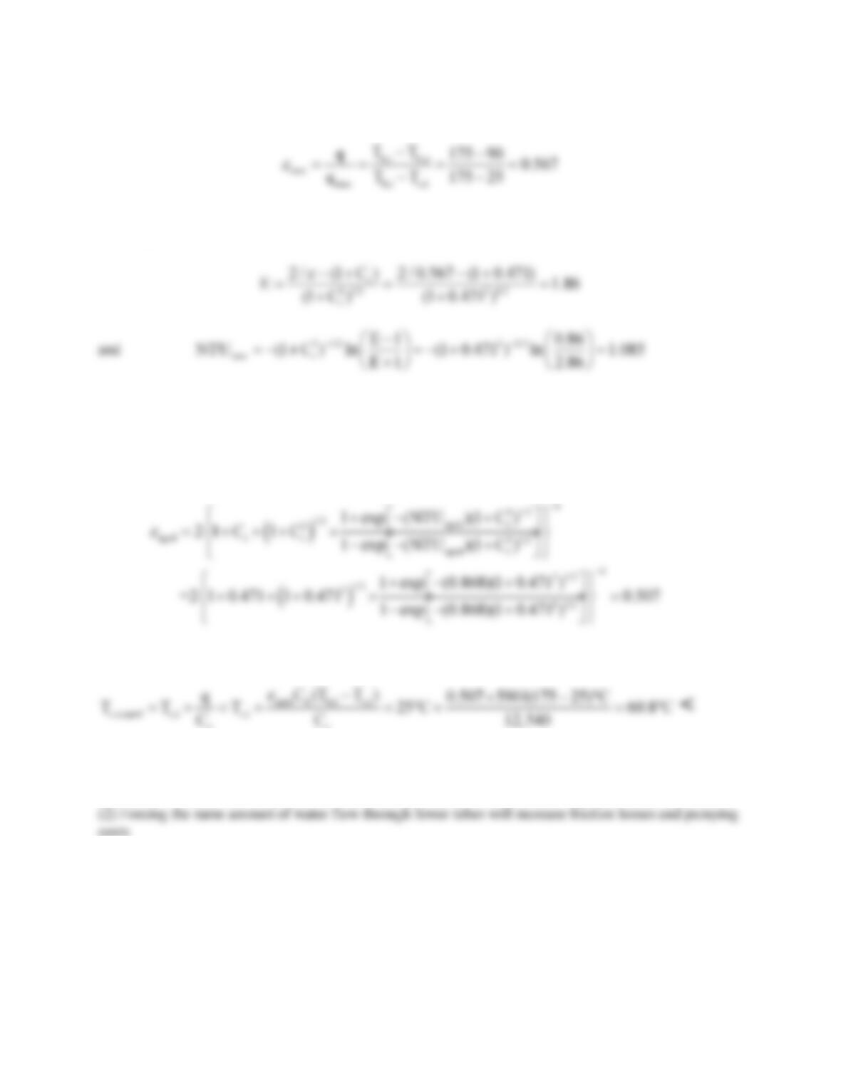
SCHEMATIC:
ASSUMPTIONS: (1) No heat losses from heat exchanger. (2) Constant properties. (3) No fouling over
time. (4) Fully–developed flow inside tubes.
PROPERTIES: Table A-6, Water (Assume
c
T
= 45°C ≈ 320 K): cp = 4180 J/kg⋅K.
ANALYSIS: The overall heat transfer coefficient consists of resistances associated with (1) air flow
over the tubes, (2) conduction through the tube walls, and (2) liquid water flow inside the tubes. Since
the properties are assumed to be constant, the air-side convection coefficient and the tube wall
The heat capacity rate for the (cold) water is
The energy balances on the hot and cold streams yield
PROBLEM 11.28 (Cont.)
When new, the effectiveness is
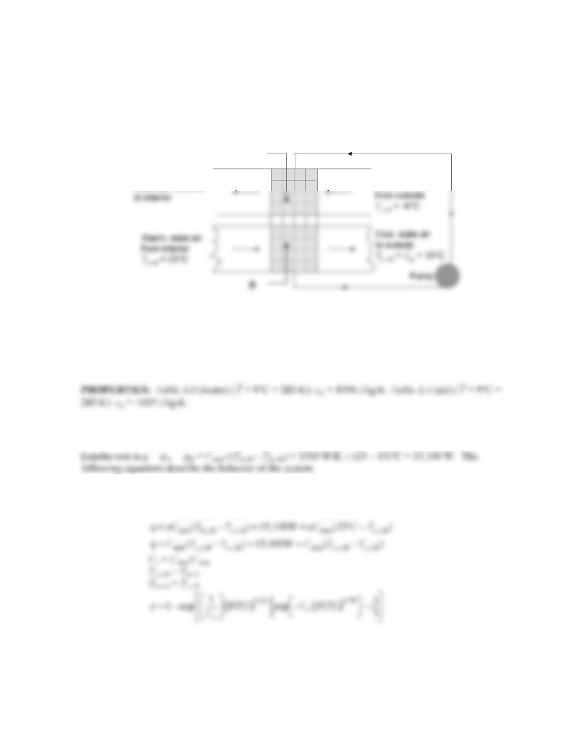
With Cr = Ch/Cc = 5901/12,540 = 0.471, the NTU under new conditions is calculated from Equation
11.30b,c,
Assuming the overall heat transfer coefficient is unchanged, the value of NTU after 20% of the tubes are
welded shut is 80% of the value of NTU under new conditions, or NTUaged = 0.8×1.085 = 0.868. The
value of Cr is unchanged.
From Equation 11.30a,
The outlet temperature of the water under the aged condition is
cc
COMMENTS: (1) The value of the overall heat transfer coefficient was assumed to be constant.
Without any fouling over time, the value of U will increase slightly over time due to the higher Reynolds
number flow in each of the operative tubes, yielding better performance after aging than predicted here.
PROBLEM 11.29
KNOWN: Air flow rate, cold outside temperature, warm indoor temperature, dew point temperature,
UA product.
FIND: (a) Required water flow rate.
SCHEMATIC:
Cold, fresh air
Warmed, fresh air
Water
A
ASSUMPTIONS: (1) Negligible heat transfer between heat exchangers and surroundings, negligible
heat transfer between two heat exchangers, (2) Constant properties, (3) Negligible energy added to the
system by the pump, (4) Cmax is associated with the air, (5) Properties of water with anti-freeze agent
are the same as properties of water.
ANALYSIS: (a) Note that
max air 1.50kg / s 1007J/kg K 1510 W/K
p
C C mc= = = × ⋅=
. The heat
( )
min min
NTU / 2500W/K /UA C C= =
min , ,A , ,A min , ,A
( ) 15,100W ( ( 4 ))
hi ci hi
qCT T CT C
ee
= − = = −−°
A trial-and-error solution yields
( )
min ,
/ 776K/W / 4194J/kg K 0.185kg/s
w pw
mC c= = ⋅=
<
Continued…
PROBLEM 11.29 (Cont.)
COMMENTS: (1) Note that the maximum allowable water flow rate to justify the assumption that
Cmax is associated with the air flow is
m
max = Cmax /cp,w = 1510 W/K/4194 J/kg⋅K = 0.36 kg/s. The
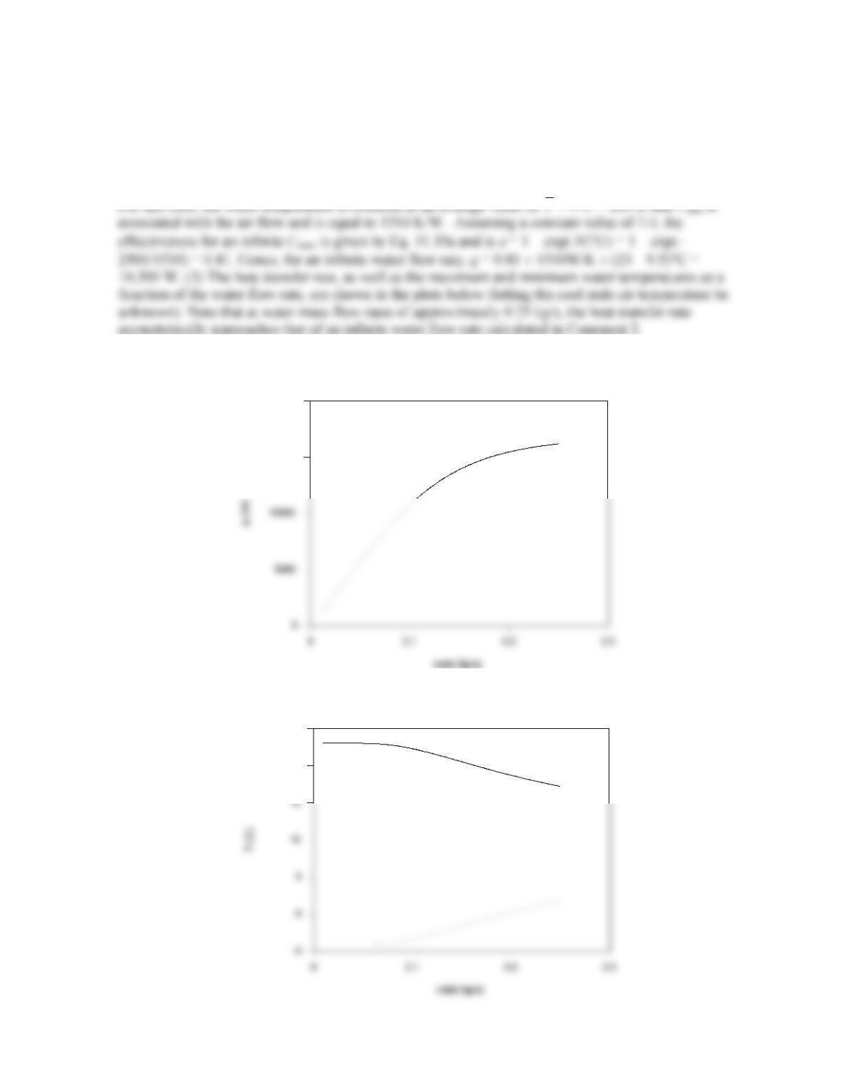
assumption is valid. (2) The maximum heat transfer rate is associated with an infinite water flow rate.
Heat Transfer Rate vs. Water Flow Rate
15000
20000
Min. & M ax. Water Temperatur es vs. Water Flow Rate
20
25
PROBLEM 11.30
KNOWN: Cross-flow heat exchanger (both fluids unmixed) cools blood to induce body hypothermia
using ice-water as the coolant.
FIND: (a) Heat transfer rate from the blood, (b) Water flow rate,
c
(liter/min), (c) Surface area of
the exchanger, and (d) Calculate and plot the blood and water outlet temperatures as a function of the
water flow rate for the range,
2 ≤ ≤
4 liter/min, assuming all other parameters remain
unchanged.
SCHEMATIC:
ASSUMPTIONS: (1) Steady-state conditions, (2) Negligible losses to the surroundings, (3) Overall
heat transfer coefficient remains constant with water flow rate changes, and (4) Constant properties.
ANALYSIS: (a) The heat transfer rate from the blood is calculated from an energy balance on the
hot fluid,
(b) From an energy balance on the cold fluid, find the coolant water flow rate,
(c) The surface area can be determined using the effectiveness–NTU method. The capacity rates for
the exchanger are
Continued …..
PROBLEM 11.30 (Cont.)
For the cross flow exchanger, with both fluids unmixed, substitute numerical values into Eq. 11.32 to
find the number of transfer units, NTU, where
C C C
rmin max
=/ .
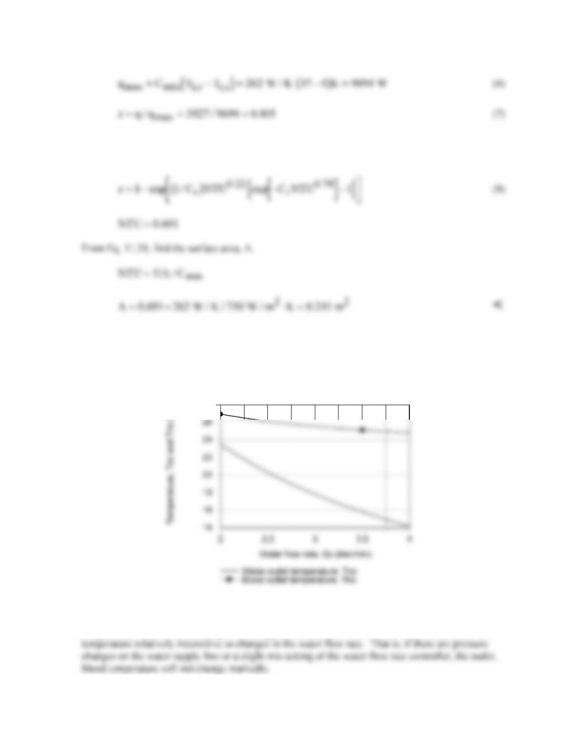
(d) Using the foregoing equations in the IHT workspace, the blood and water outlet temperatures, Th,o
and Tc,o, respectively, are calculated and plotted as a function of the water flow rate, all other
parameters remaining unchanged.
Outlet temperatures for blood flow rate 5 liter/min
28
From the graph, note that with increasing water flow rate, both the blood and water outlet
temperatures decrease. However, the effect of the water flow rate is greater on the water outlet
temperature. This is an advantage for this application, since it is desirable to have the blood outlet
PROBLEM 11.31
KNOWN: Shell-and-tube (one shell, two tube passes) heat exchanger design. Water flow rate and inlet
temperature. Steam pressure and convection coefficient.
FIND: (a) Water outlet temperature, Tc,o; (b) Tc,o as a function of flow rate,
m
, for the range, 5 ≤
m
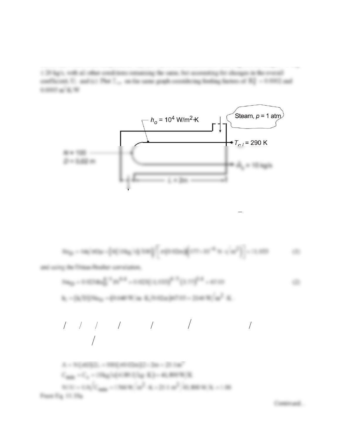
SCHEMATIC:
ASSUMPTIONS: (1) Negligible heat loss to surroundings, (2) Negligible wall conduction and fouling
resistances, (3) Constant properties.
PROPERTIES: Table A-6, Sat. water (p = 1.0133 bar): Tsat = T = 373.1 K; (
c
T≈
320 K): cp = 4180
J/kg⋅K, µ = 577 × 10-6 N⋅s/m2 , k = 0.640 W/m⋅K, Pr = 3.77.
ANALYSIS: Using the NTU–effectiveness method, calculate U by finding hi . With
From Eq. 11.5
( ) ( )
[ ]
2 42
io
1 U 1 h 1 h 1 10, 000 1 2146 m K W 5.66 10 m K W
−
=+= + ⋅ =× ⋅
(3)
2
U 1766 W m K= ⋅
.
The heat transfer surface area, capacity rates and NTU are
PROBLEM 11.31 (Cont.)
( ) ( )
1 exp NTU 1 exp 1.06 0.654
e
=−− =−− =
. (4)
(b,c) Using the IHT Heat Exchanger Tool, All Exchangers, Cr
=
0, the Properties Tool for Water and the
Correlation Tool, Forced Convection, Internal Flow, for Turbulent, fully developed conditions, a model
was developed following the foregoing analysis to compute and plot the outlet temperature Tc,o as a
function of the cold fluid flow rate,
c
m
. The expression for the overall coefficient, Eq.(1), was modified
to include the fouling factor,
if o
1U 1h R 1h
′′
= ++
.
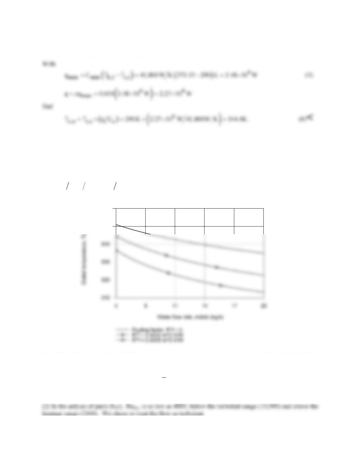
350
360
The effect of increasing the cold flow rate is to decrease the outlet temperature. The effect of the fouling
resistance is to decrease the outlet temperature as well.
COMMENTS: (1) For the part (a) analysis,
c
T
= 317 K and the initial guess of 320 K was reasonably
good.
PROBLEM 11.32
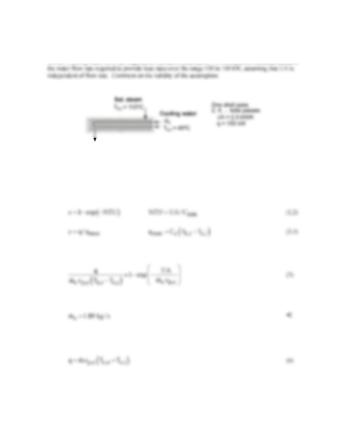
KNOWN: Saturated steam at 110°C condensing in a shell and tube heat exchanger (one shell pass, 2,
4, tube passes) with a UA value of 2.5 kW/K; cooling water enters at 40°C.
FIND: Cooling water flow rate required to maintain a heat rate of 150 kW; and (b) Calculate and plot
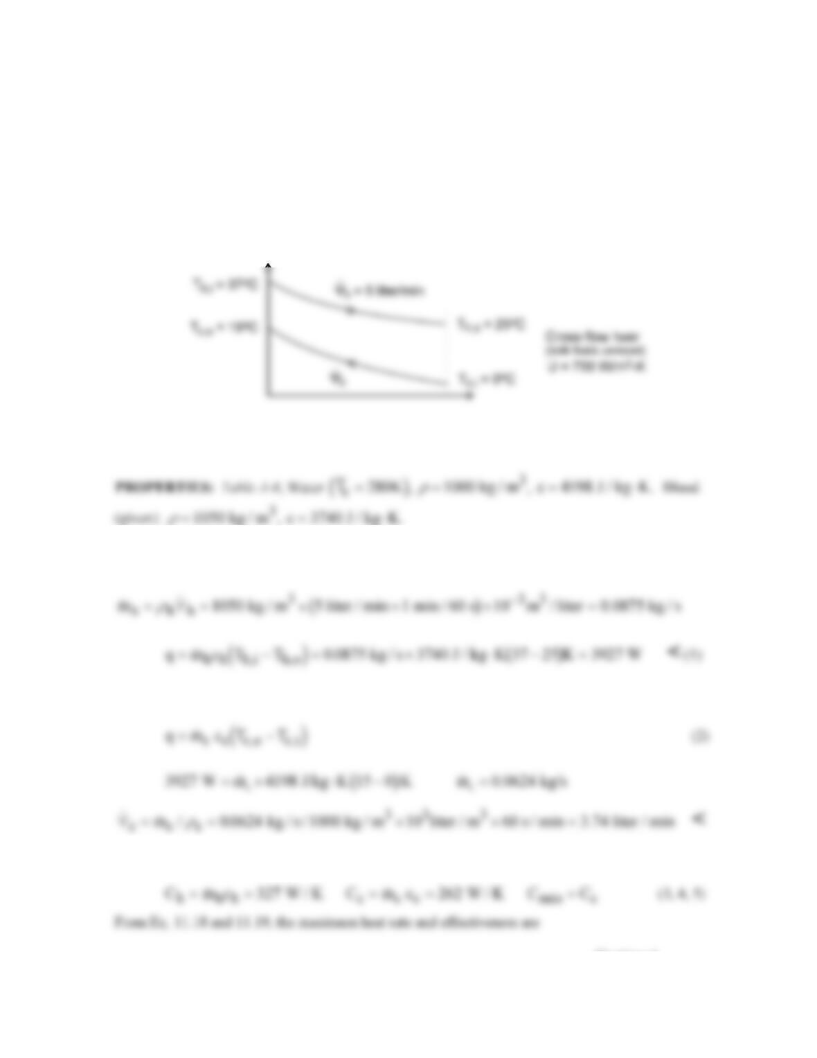
SCHEMATIC:
ASSUMPTIONS: (1) Negligible heat loss to surroundings, (2) UA independent of flow rate, and (3)
Constant properties.
PROPERTIES: Table A-6, Water (Tm,c = (Tc,i + Tc,o)/2 = 49.5°C = 322.5 K): cp,c = 4181 J/kg⋅K.
ANALYSIS: (a) For the shell-tube heat exchanger with any multiple of two-tube passes, from Eq.
11.35a with Cr = 0, using Eqs. 11.19 and 11.22,
By combining the equations with
min c c p,c
C C mc ,= =
Substituting numerical values, and solving using IHT find
The specific heat of the cold fluid, cp,c, is evaluated at the average of the mean inlet and outlet
temperatures, Tm,c = (Tc,i + Tc,o)/2, with Tc,o determined from the energy balance equation,
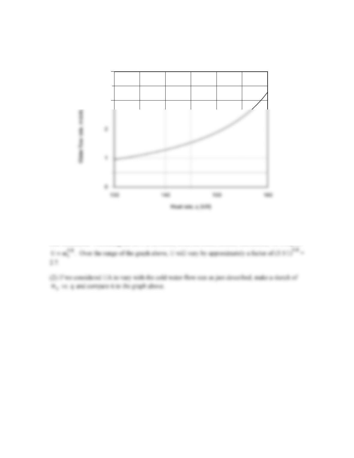
(b) Solving the above system of equations in the IHT workspace, the graph below illustrates the water
flow rate required to provide a range of heat rates.
Continued …
PROBLEM 11.32 (Cont.)
COMMENTS: (1) The assumption that UA is constant with flow rate is a poor one. Because the
heat transfer coefficient for condensation is so high, the overall coefficient is controlled by the water–
side coefficient. Presuming the flow is turbulent, from the Dittus-Boelter correlation, we’d expect
Water flow rate required for specified heat rate
3
4
PROBLEM 11.33
KNOWN: Temperature, convection coefficient and condensation rate of saturated steam. Tube
diameter for shell–and-tube heat exchanger with one shell pass and two tube passes. Velocity and
inlet and maximum allowable exit temperatures of cooling water.
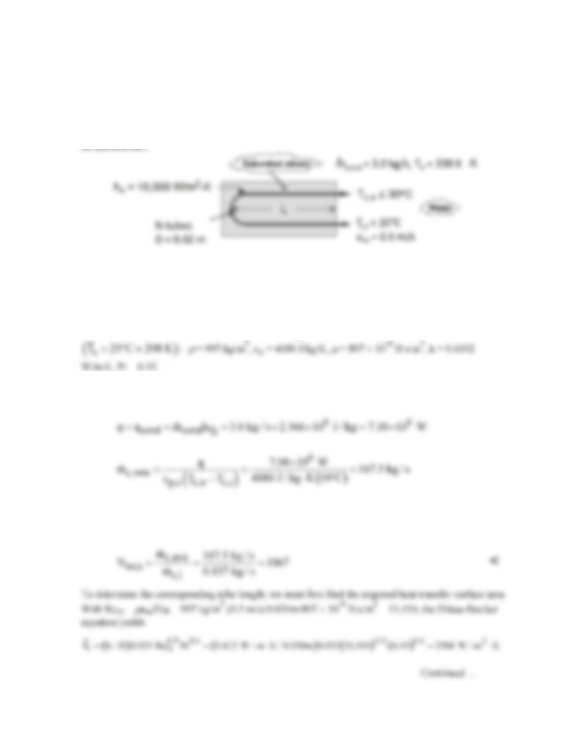
FIND: (a) Minimum number of tubes and tube length per pass, (b) Effect of tube-side heat transfer
enhancement on tube length.
ASSUMPTIONS: (1) Negligible heat exchange with surroundings, (2) Negligible tube wall
conduction and fouling resistance, (3) Constant properties, (4) Fully developed internal flow
throughout.
PROPERTIES: Table A-6, Sat. water (330 K): hfg = 2.366 × 10⁶ J/kg; Sat. water
ANALYSIS: (a) The required heat rate and the maximum allowable temperature rise of the water
determine the minimum allowable flow rate. That is, with
With a specified flow rate per tube of
c,1
m
=
ρ
umπ D2/4 = 997 kg/m3 × 0.5 m/s × π (0.02m)2/4 =
0.157 kg/s, the minimum number of tubes is