Mohr Circle and Strength Testing Chapter 11
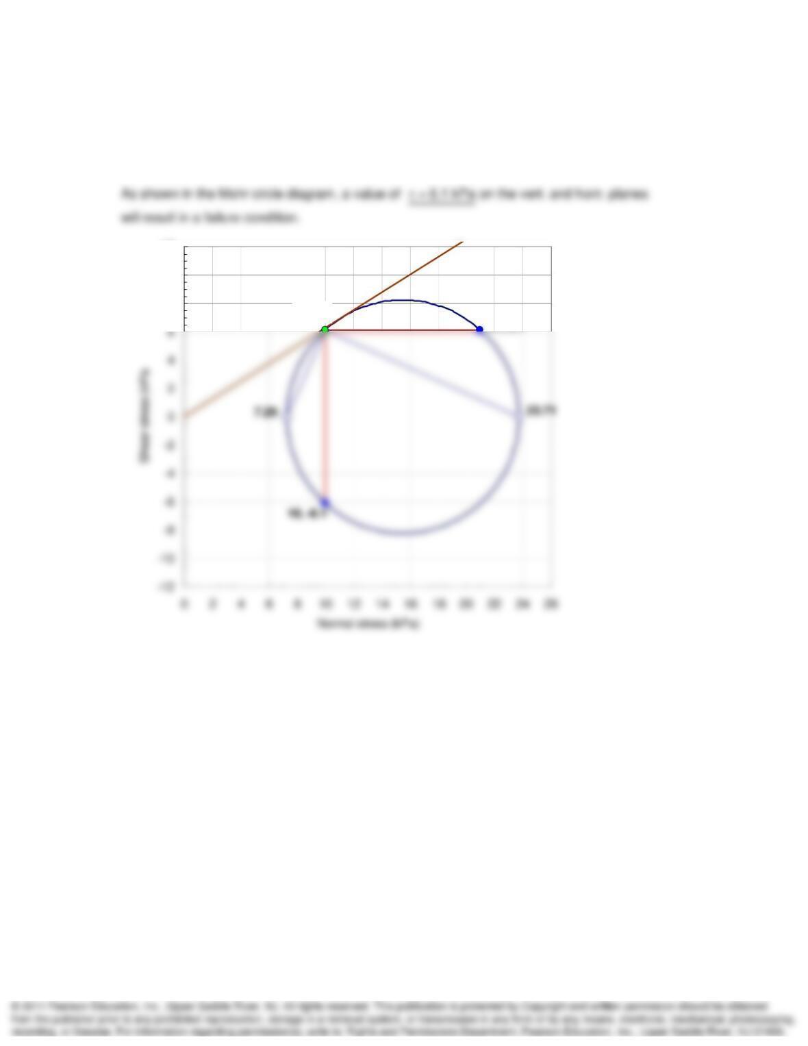
11-13. Given the vertical and horizontal normal stresses of Problem 11.12. Find the maximum
values of shear stress on the horizontal and vertical planes to cause failure in a medium dense
sand. Assume the angle of internal friction for the sand is 32°.
SOLUTION:
21, 6.1
10, 6.1
8
10
12
Mohr Circle and Strength Testing Chapter 11
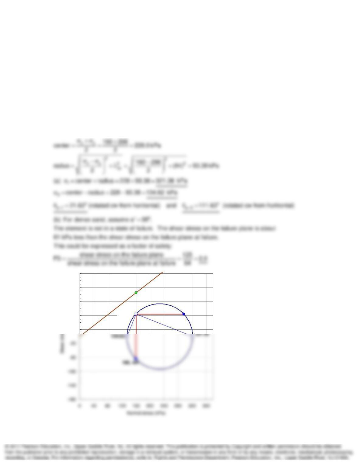
11-14. The state plane stress in a mass of dense cohesionless sand is described by the following
stresses:
Normal stress on horizontal plane = 296 kPa
Normal stress on vertical plane = 160 kPa
Shear stress on horizontal and vertical planes = +/- 64 KPa
Determine by means of the Mohr circle the magnitude and direction of the principal stresses. Is
this state of stress safe against failure? (After A. Casagrande.)
SOLUTION:
xyxy
Solve using Mohr‘s circle and the pole method (see plot below).
160 kPa, 296 kPa, 64 kPa
296, 64
160, 64
20
60
100
140
180
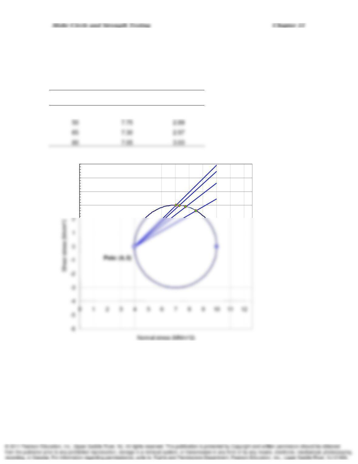
11-15. At a given point within a sand deposit the major, intermediate, and minor principal
stresses are 10, 6, and 4 Mn/m2, respectively. Construct the Mohr diagram, and from it scale the
normal and shearing stresses and the obliquity angles on planes at 35°, 50°, 65°, and 80° from
the major principal plane. (After Taylor, 1948.)
SOLUTION:
Angle (deg)
Normal stress
(MN/m2)
Shear Stress
(MN/m2)
35 8.5 2.60
35 deg
50 deg
65 deg
80 deg
3
4
5
6
Mohr Circle and Strength Testing Chapter 11
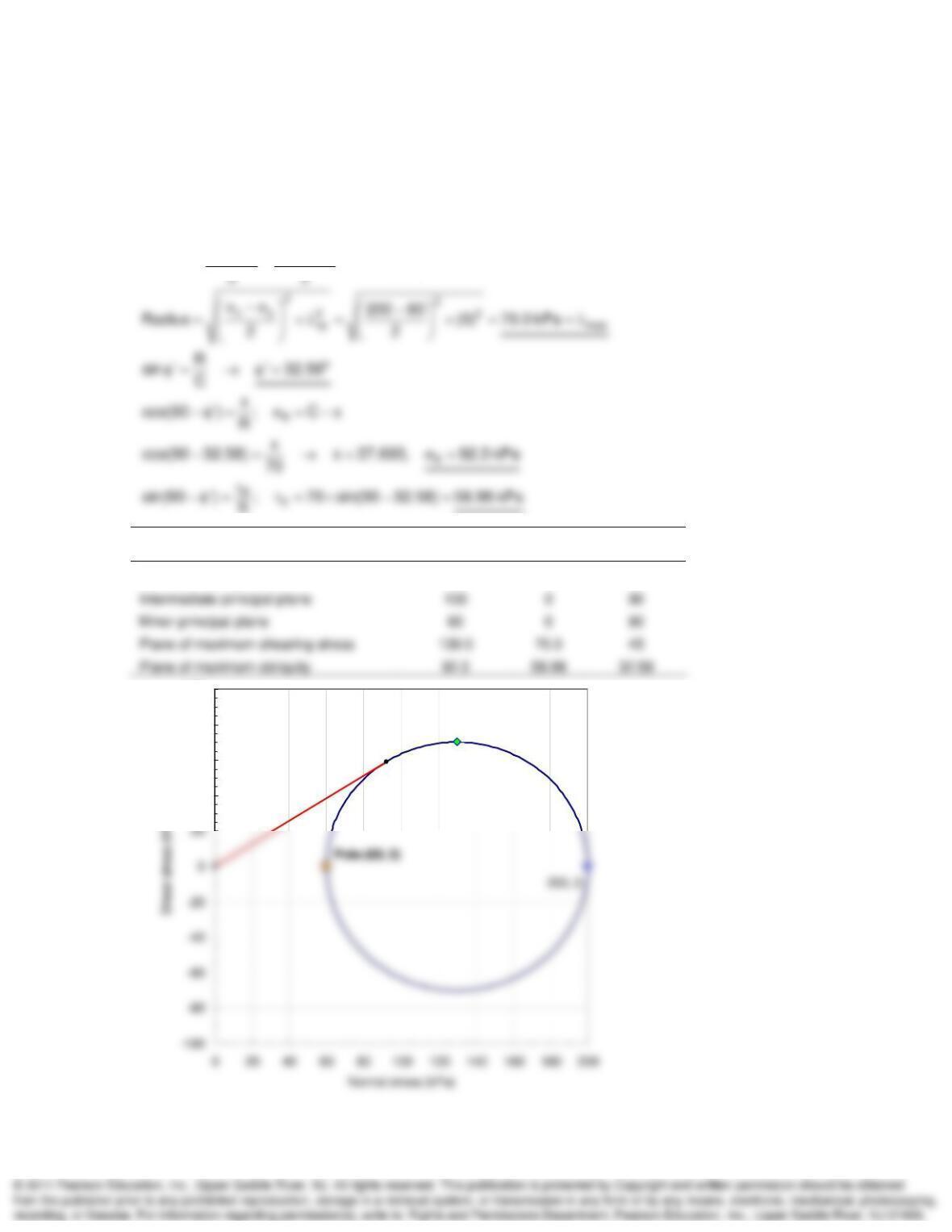
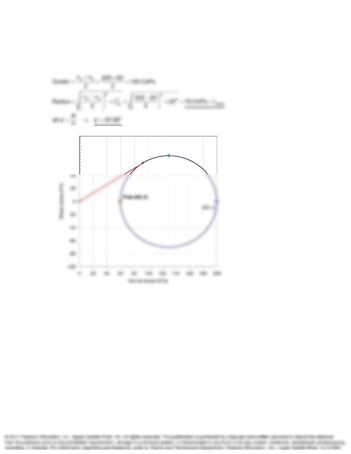
11-16. A 1-m cube within a mass of stressed soil has a stress of 200 kPa on its top and bottom
faces, 100 kPa on one pair of vertical faces, and 60 kPa on the other pair of vertical faces. There
is no shear stress on any face. Fill in the following table. (After Taylor, 1948.)
SOLUTION:
123
xy
200 kPa, 100 kPa, 60 kPa
200 60
Center 130.0 kPa
R
(kPa)
(kPa)
(deg)
Major principal plane 200 0 0
130, 70
92.3, 58.98
40
60
80
100
Mohr Circle and Strength Testing Chapter 11
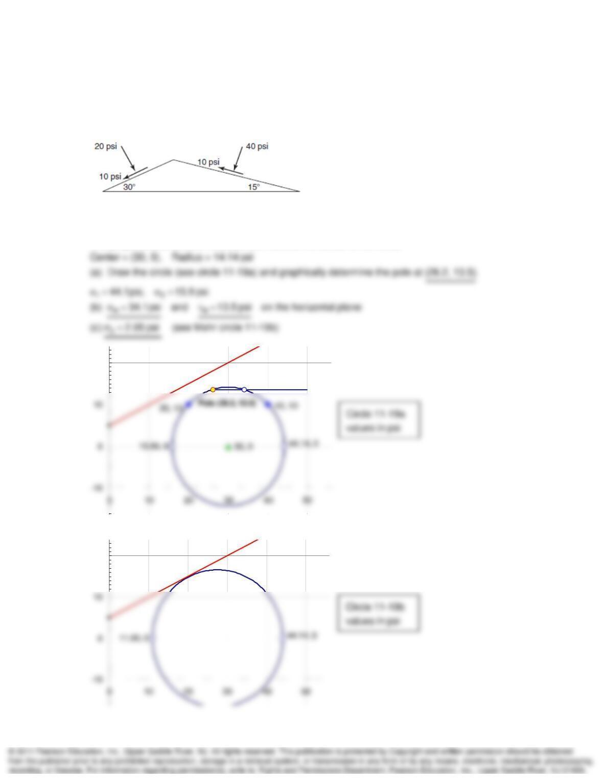
11-17. In Problem 11.16 what is
, assuming c = 0?
SOLUTION:
123
200 kPa, 100 kPa, 60 kPa
C
130, 70
92.3, 58.98
60
80
100
Mohr Circle and Strength Testing Chapter 11
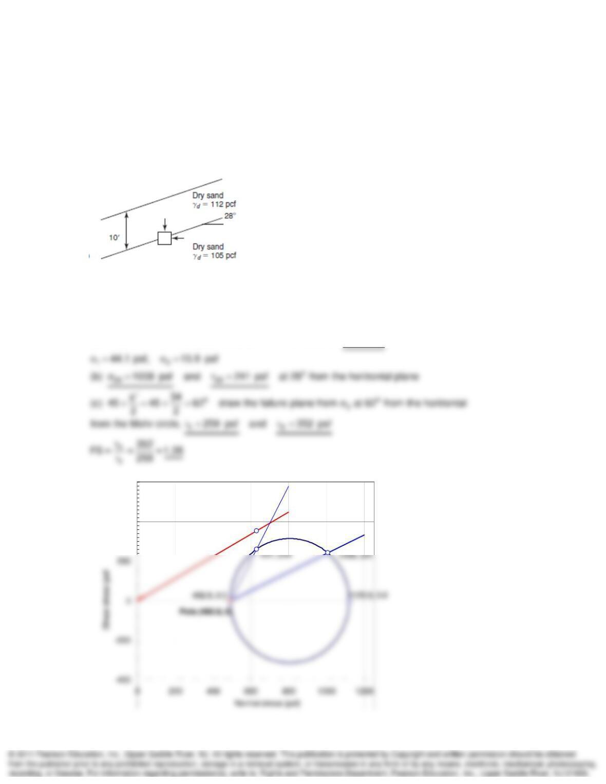
11-19. (a) Draw the Mohr circle for this point, showing the pole location. (b) What are the
stresses acting on a horizontal plane passing through this point? (c) The cohesion intercept for
this soil is and the friction angle is If the major principal stress remains the same, what would the
minor principal stress have to be to cause failure?
SOLUTION:
Plot (40, 10) and (20, 10), and construct a perpendicular bisector.
The perpendicular bisector crosses the x-axis at the center of the circle.
34.1, 13.5
20
20
Mohr Circle and Strength Testing Chapter 11
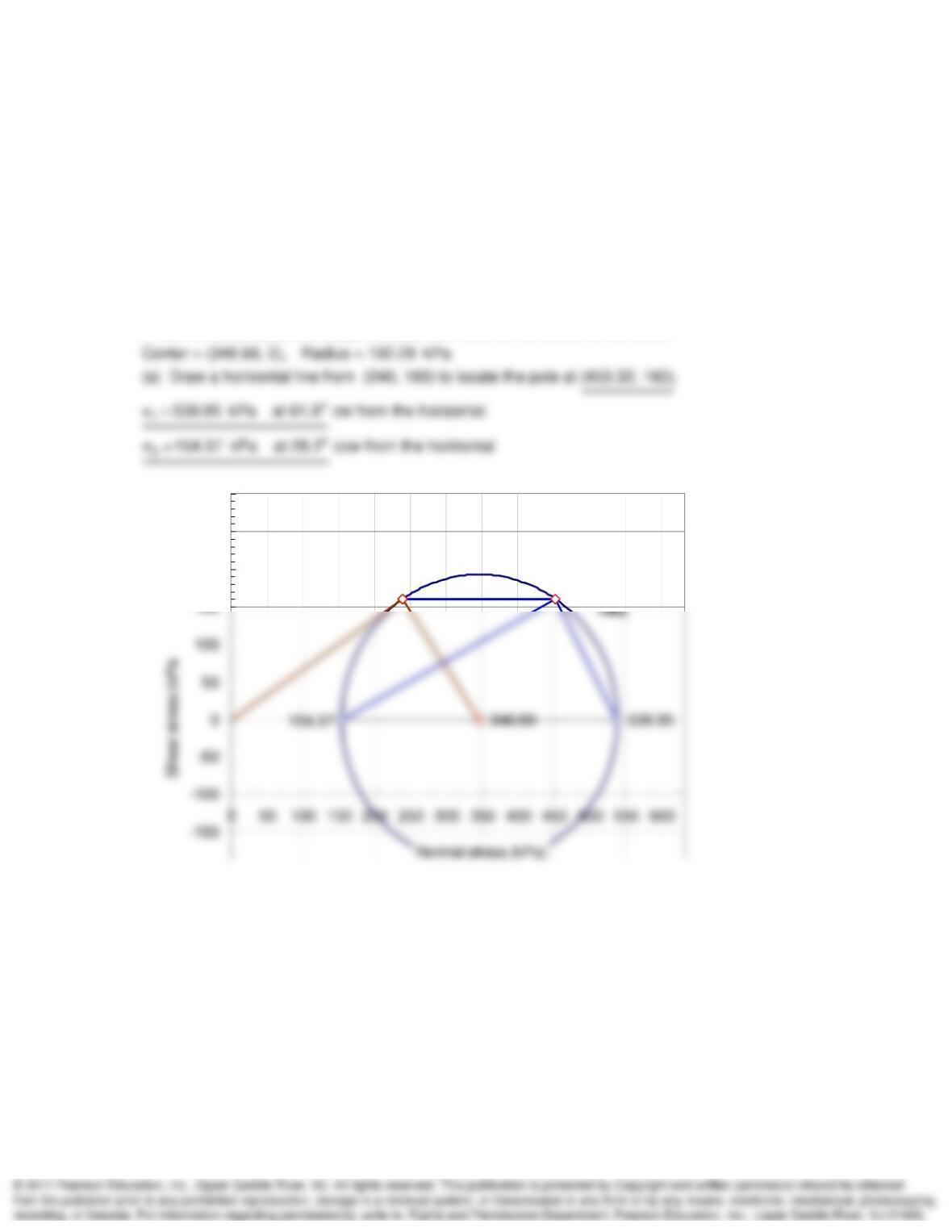
11-20. The figure shows an element of soil at the interface between two dry sand layers on a 28°
slope. The interface is 10 ft below the ground surface, and for both sand layers the friction angle
is 34° and Ko = 0.44. Assume that the shear stress is zero on both the vertical and horizontal
planes. (a) Draw the Mohr circle for this point, and determine the pole location. (b) Determine
the normal and shear stresses on the soil interface (i.e., on the 28° plane). (c) What is the shear
stress on the failure plane (
f) and what is the shear stress on the failure plane at failure (
ff)?
Use these values to determine the factor of safety.
SOLUTION:
vhov
‘ (112 pcf)(10 ft) 1120 psf, ‘ K ‘ (0.44)(1120) 492.8 psf
Plot (1120, 0) and (492.8, 0), and draw the Mohr circle (see below).
Center = (806.4, 0), Radius = 313.6 psf
(a) Draw the circle and graphically
determine the pole at (492.8, 0).
631, 352
400
600
Mohr Circle and Strength Testing Chapter 11
11-26. In a direct shear test on a specimen of cohesionless sand, the vertical normal stress on
the specimen is 240 kN/m2 and the horizontal shear stress at failure is 160 kN/m2. (a) Assuming
uniform stress distribution within the failure zone and a straight line failure envelope which goes
through the origin, determine by means of the Mohr circle the magnitude and direction of the
principal stresses at failure.
SOLUTION
o
Plot (240, 160) and (0, 0). This defines the failure envelope at 33.69 .
A normal to the failure envelope crosses the x-axis at the center of the circle.
240, 160 Pole (453.32,
200
250
300
Mohr Circle and Strength Testing Chapter 11
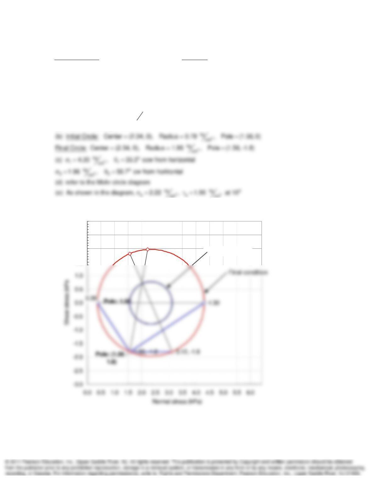
11-27. A specimen of sand is tested in direct simple shear. The stress conditions are shown.
Initial conditions:
v = 3.12 kg/cm2, Ko = 0.5 At failure:
v = 3.12 kg/cm2,
hv = 1.80 kg/cm2
(a) Draw the Mohr circles for both initial and final stress conditions. (b) Show clearly the locations
of the poles of these circles. (c) Determine the magnitude and orientation of the principal
stresses at failure. (d) What is the orientation of the failure plane? (e) If the shear strain at failure
is 10° as shown in the figure, what are the stresses and on the sides of the specimen at failure?
SOLUTION:
2
kg
hov cm
K (0.5)(3.12) 1.56
(a) See Mohr circle plot below.
1.56, 1.8
2.22, 1.96
1.5
2.0
2.5
3.0
Initial condition
Mohr Circle and Strength Testing Chapter 11
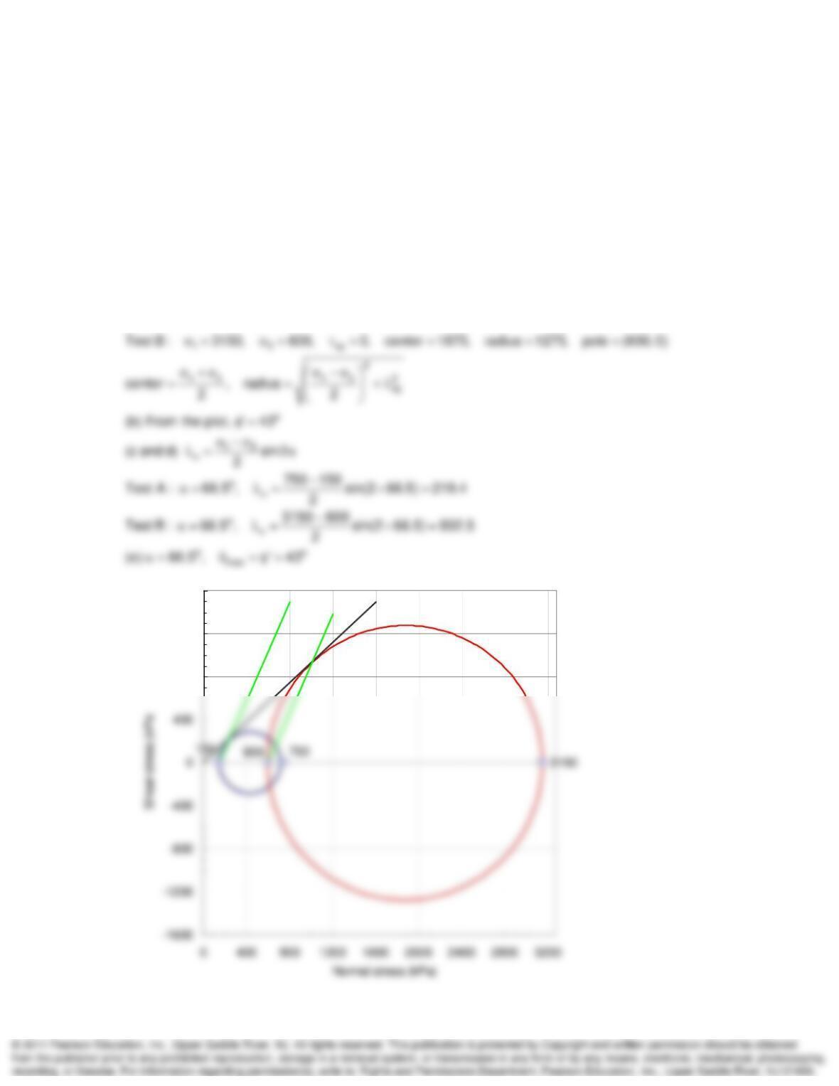
11-28. Two conventional CD triaxial compression tests were conducted on a dense angular dry
sand at the same void ratio. Test A had a confining pressure of 150 kPa, while in test B the
confining pressure was 600 kPa; these stresses were held constant throughout the test. At
failure, tests A and B had maximum principal stress differences of 600 and 2550 kPa,
respectively. (a) Plot the Mohr circles for both tests at initial conditions and at failure. (b)
Assuming c = 0, determine
. (c) What is the shear stress on the failure plane at failure for both
tests? (d) Determine the theoretical orientation of the failure plane in each specimen. (e) What is
the orientation of the plane of maximum obliquity?
SOLUTION:
13xy
(a) Solve using Mohr‘s circle and the pole method (see plot).
Test A : 750, 150, 0, center 435, radius 285, pole (150, 0)
800
1200
1600
Mohr Circle and Strength Testing Chapter 11
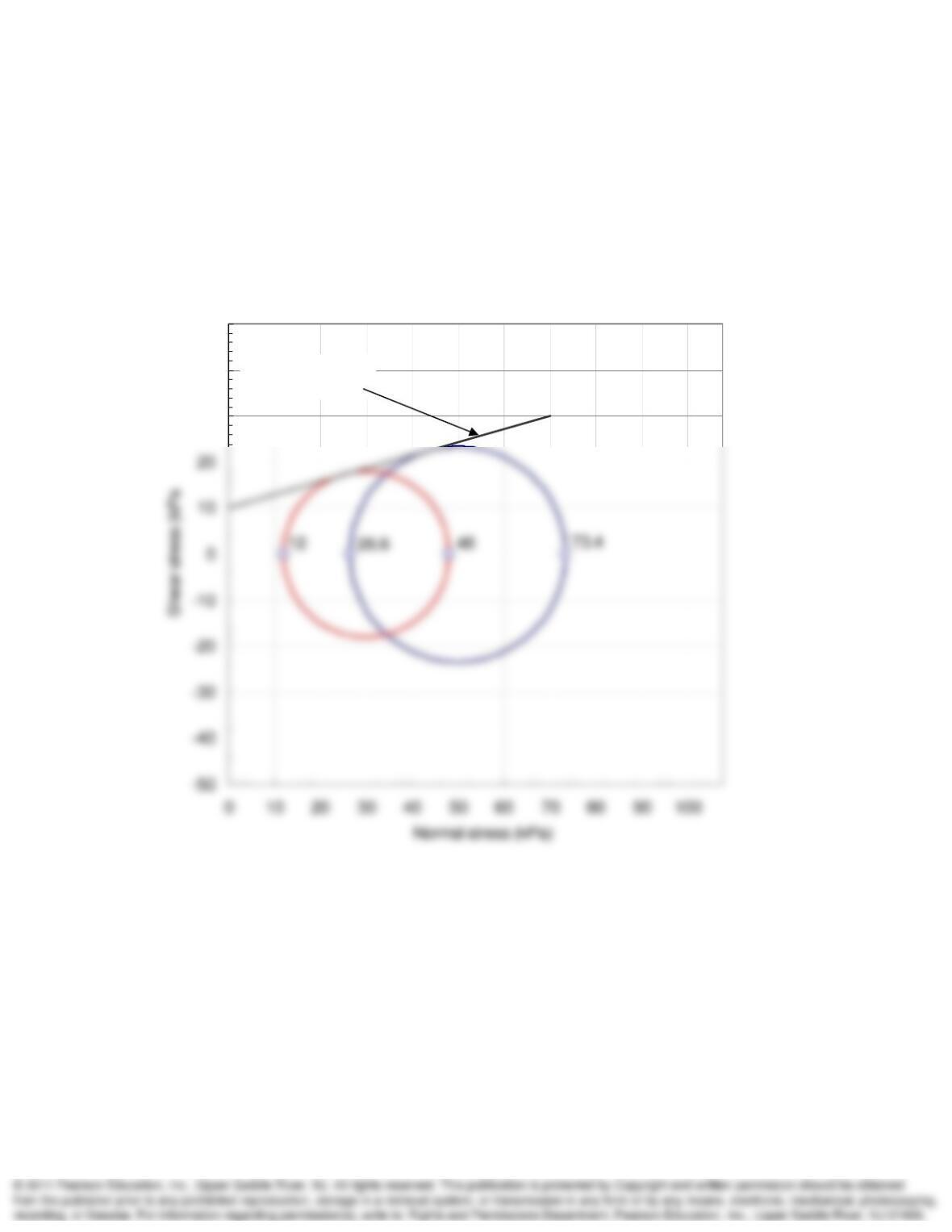
11-29. Two consolidated–drained triaxial tests were performed on specimens of the same clay,
with the following results at failure:
Test 1:
’1 = 73.4 psi,
’3 = 26.6 psi
Test 2:
’1 = 48.0 psi,
’3 = 12.0 psi
Determine the effective Mohr–Coulomb failure envelope (
’ and c) based on these test results.
SOLUTION:
o
From the M-C plot shown below: 17 and c 10 psi.
30
40
50
Mohr-Coulomb
failure envelo
p
e
Mohr Circle and Strength Testing Chapter 11
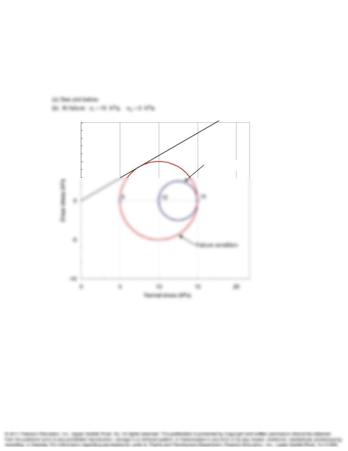
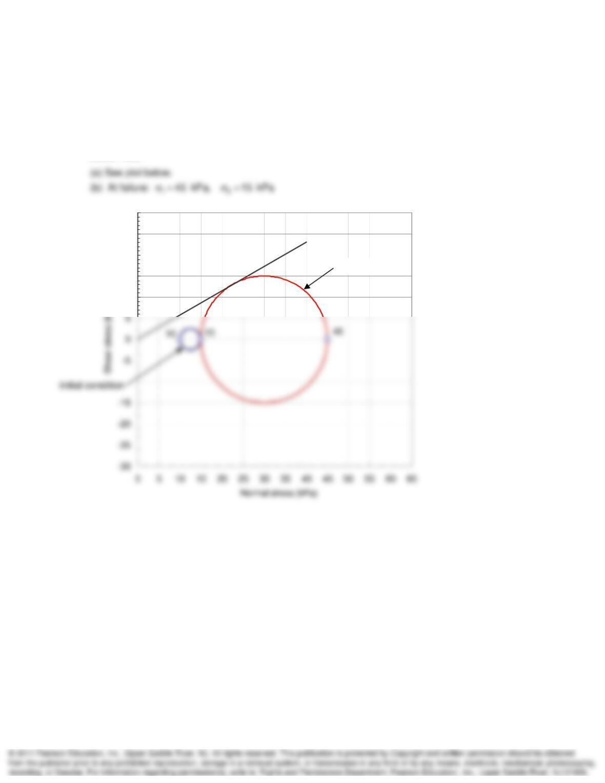
11-30. A triaxial specimen of loose sand is first consolidated nonhydrostatically, with
1 = 15 kPa
and
3 = 10 kPa. The sample is then failed by holding the vertical stress constant and decreasing
the horizontal stress (this is a lateral extension test). The angle of internal friction is 30° (c = 0).
(a) Draw the Mohr circles for both initial and “at failure” conditions. (b) What will be the major and
minor principal stresses at failure?
SOLUTION:
5
10
Initial condition
Mohr Circle and Strength Testing Chapter 11
11-31. Another sample of the same sand tested in Problem 11.30 (consolidated
nonhydrostatically, with
1 = 15 kPa and
3 = 10 kPa) is tested by holding the vertical stress
constant and increasing the horizontal stress (this is a lateral compression test). The angle of
internal friction is 30° (c = 0). (a) Draw the Mohr circles for both initial and “at failure” conditions.
(b) What will be the major and minor principal stresses at failure?
SOLUTION:
10
15
20
25
30
Fin
a
l
co
n
d
i
t
i
o
n