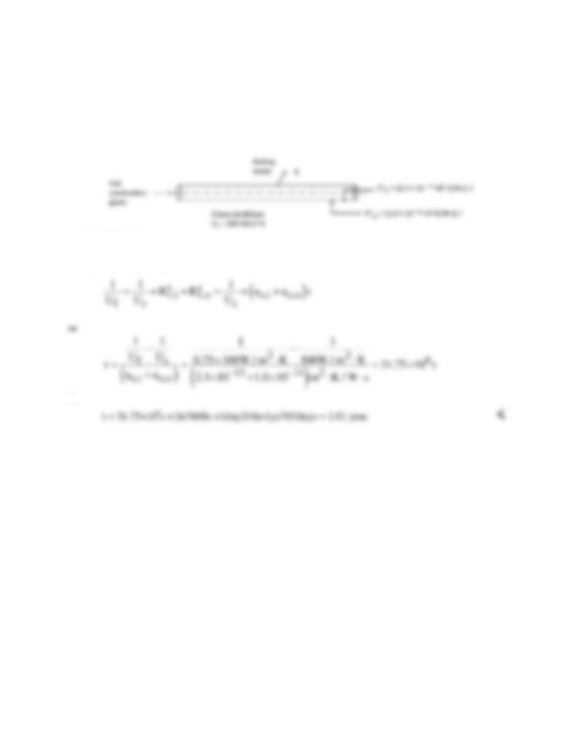
PROBLEM 11.1
KNOWN: Overall heat transfer coefficient of clean boiler. Rate at which fouling factors on inner and
outer tube surfaces increase with time. Percent reduction in overall heat transfer coefficient that
corresponds to need for cleaning.
FIND: Time after first installation of clean boiler corresponding to the first cleaning.
SCHEMATIC:
ASSUMPTIONS: (1) Continuous operation between cleanings.
ANALYSIS: From Equation 11.5:
or
COMMENTS: Fouling rates may be affected by changes in the chemical compositions of the fuel and/or
water.
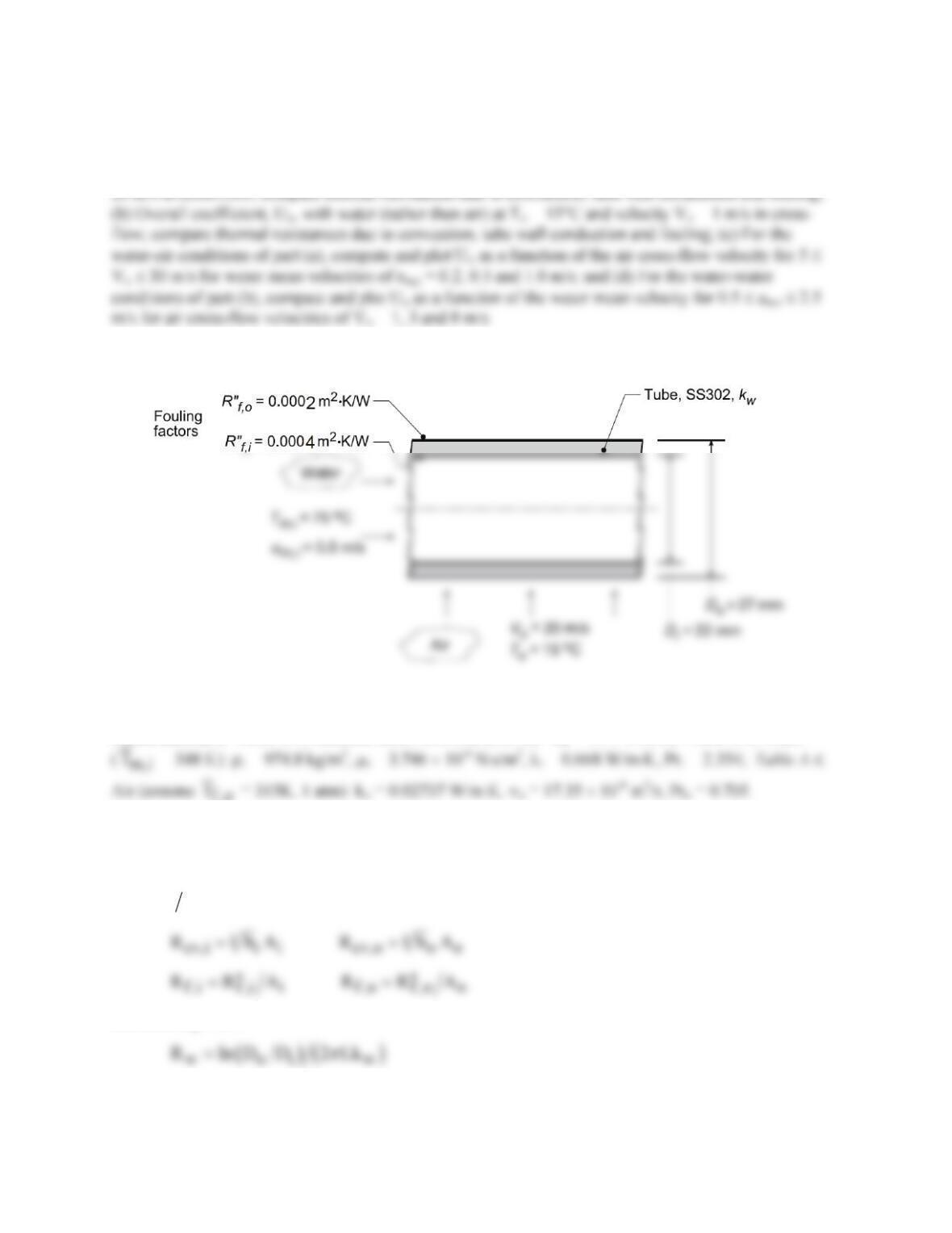
PROBLEM 11.2
KNOWN: Type–302 stainless tube with prescribed inner and outer diameters used in a cross–flow heat
exchanger. Prescribed fouling factors and internal water flow conditions.
FIND: (a) Overall coefficient based upon the outer surface, Uo, with air at To =15°C and velocity Vo =
SCHEMATIC:
ASSUMPTIONS: (1) Steady-state conditions, (2) Fully developed internal flow.
PROPERTIES: Table A.1, Stainless steel, AISI 302 (300 K): kw = 15.1 W/m⋅K; Table A.6, Water
f ,o
ANALYSIS: (a) For the water-air condition, the overall coefficient, Eq. 11.1, based upon the outer area
can be expressed as the sum of the thermal resistances due to convection (cv), tube wall conduction (w)
and fouling (f):
o o tot cv,i f ,i w f ,o cv,o
1U A R R R R R R= = + ++ +
and from Eq. 3.33,
The convection coefficients can be estimated from appropriate correlations.
Continued…
PROBLEM 11.2 (Cont.)
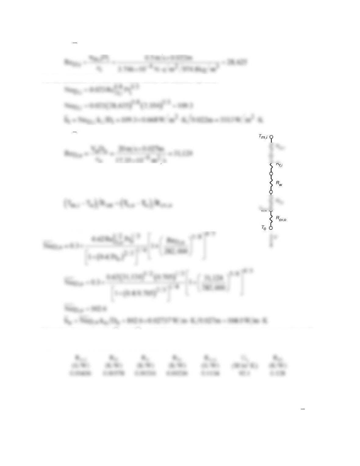
Estimating
i
h
: For internal flow, characterize the flow evaluating thermophysical properties at Tm,i with
For the turbulent flow, use the Dittus-Boelter correlation, Eq. 8.60,
Estimating
h
o
: For external flow, characterize the flow with
evaluating thermophysical properties at Tf,o = (Ts,o + To)/2 when the
surface temperature is determined from the thermal circuit analysis
result,
Assume Tf,o = 315 K, and check later. Using the Churchill-Bernstein
correlation, Eq. 7.54, find
Using the above values for
i
h
, and
o
h
, and other prescribed values, the thermal resistances and overall
coefficient can be evaluated and are tabulated below. <
The major thermal resistance is due to outside (air) convection, accounting for 89% of the total
resistance. The other thermal resistances are of similar magnitude, nearly 50 times smaller than Rcv,o .
(b) For the water–water condition, the method of analysis follows that of part (a). For the internal flow,
the estimated convection coefficient is the same as part (a). For an assumed outer film coefficient,
f ,o
T
=
292 K, the convection correlation for the outer water flow condition Vo = 1 m/s and To = 15°C,find
Continued…
PROBLEM 11.2 (Cont.)
The thermal resistances and overall coefficient are tabulated below. <
Note that the thermal resistances are of similar magnitude. In contrast with the results for the water–air
condition of part (a), the thermal resistance of the outside convection process, Rcv,o , is nearly 50 times
smaller. The overall coefficient for the water–water condition is 7.5 times greater than that for the water–
air condition.
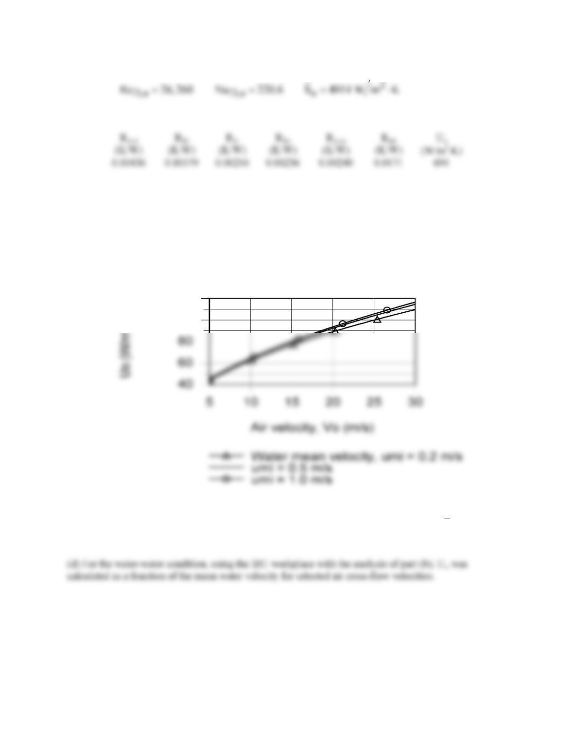
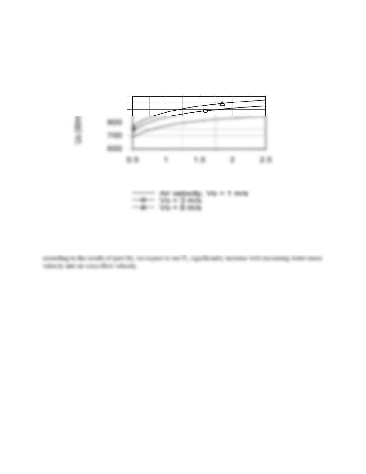
(c) For the water–air condition, using the IHT workspace with the analysis of part (a), Uo was calculated
as a function of the air cross–flow velocity for selected mean water velocities.
Water (i) – air (o) condition
100
120
The effect of increasing the cross–flow air velocity is to increase Uo since the Rcv,o is the dominant
thermal resistance for the system. While increasing the water mean velocity will increase
i
h
, because
Rcv,i << Rcv,o , this increase has only a small effect on Uo.
Continued…
PROBLEM 11.2 (Cont.)
Water (i) – water (o) condition
Water mean velocity, umi (m/s)
900
1000
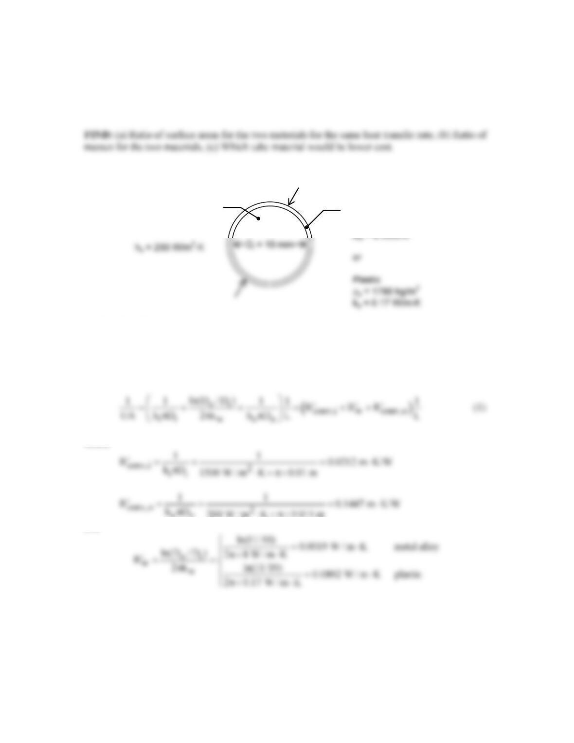
Because the thermal resistances for the convection processes, Rcv,i and Rcv,o , are of similar magnitude
PROBLEM 11.3
KNOWN: Inner and outer diameters of tubes in shell-and-tube heat exchanger. Inner and outer
heat transfer coefficients. Properties of plastic and metal candidate wall materials.
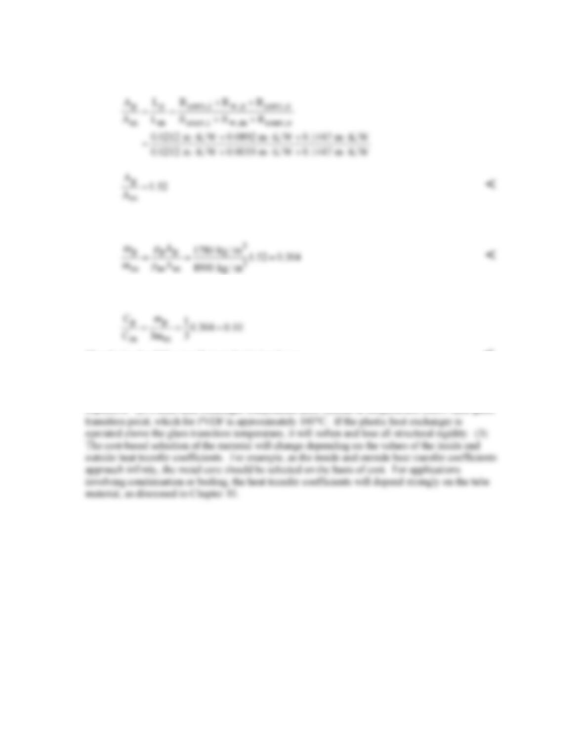
SCHEMATIC:
ASSUMPTIONS: (1) Steady–state conditions, (2) Negligible fouling.
ANALYSIS: (a) From Eq. 11.14, the heat transfer rates will be the same for the two wall
materials when UA is the same for both. From Eq. 11.1, with no fouling or fins, and with the
wall resistance given by Eq. 3.33,
where
oo
and
Thus, from Eq. (1), (UA)m = (UA)p implies the following ratio of areas,
Continued…
Do = 11 mm
h
i
= 1500 W/m2⋅K
Metal alloy
ρm = 8900 kg/m3
PROBLEM 11.3 (Cont.)
(b) The mass ratio is found as follows,
(c) The cost ratio is
The plastic should be specified on the basis of cost. <
COMMENTS: (1) Because of its lower thermal conductivity, the plastic heat exchanger wall
requires 50% more surface area than the metal wall. Nonetheless, it is 70% lighter and 90% less
expensive. (2) Plastic heat exchanger components must operate at temperatures below their glass
PROBLEM 11.4
KNOWN: Geometry of finned, annular heat exchanger. Gas-side temperature and convection
coefficient. Water–side flowrate and temperature.
FIND: Heat rate per unit length.
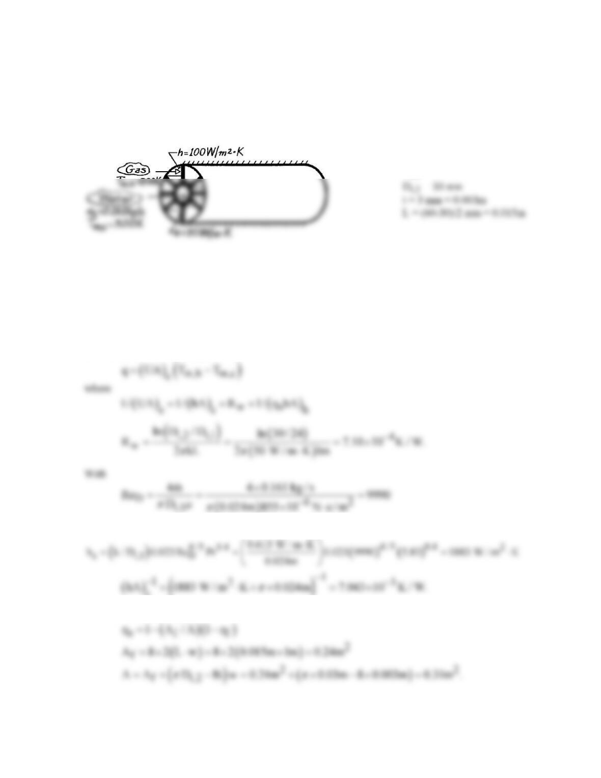
SCHEMATIC:
Do = 60 mm
Di,1 = 24 mm
ASSUMPTIONS: (1) Steady-state conditions, (2) Constant properties, (3) One-dimensional
conduction in strut, (4) Adiabatic outer surface conditions, (5) Negligible gas-side radiation, (6) Fully-
developed internal flow, (7) Negligible fouling.
PROPERTIES: Table A-6, Water (300 K): k = 0.613 W/m⋅K, Pr = 5.83,
m
= 855 × 10-6 N⋅s/m2.
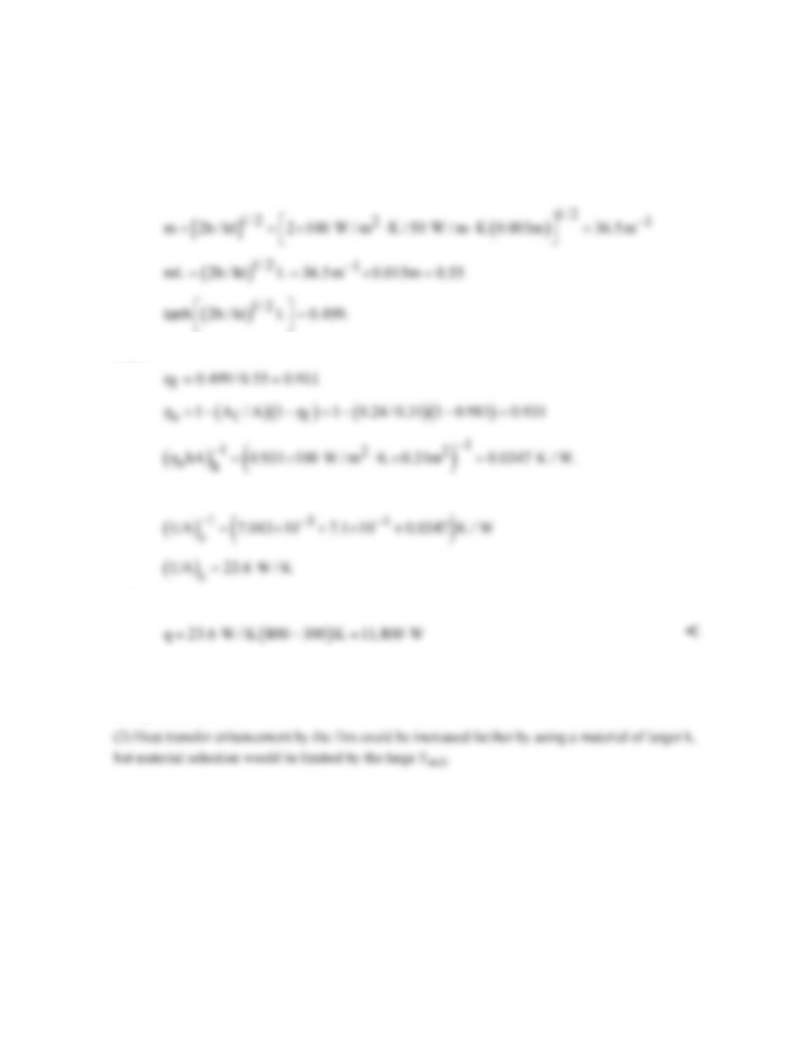
ANALYSIS: The heat rate is
internal flow is turbulent and the Dittus–Boelter correlation gives
c
Find the fin efficiency as
Continued…
PROBLEM 11.4 (Cont.)
From Eq. 11.4,
( )
f
tanh mL
mL
h
=
where
Hence
Hence
and
for a 1m long section.
COMMENTS: (1) The gas-side resistance is substantially decreased by using the fins (Af >>
π
Di,2)
and q is increased.
PROBLEM 11.5
KNOWN: Number, inner and outer diameters, and thermal conductivity of condenser tubes.
Convection coefficient at outer surface. Overall flow rate, inlet temperature and properties of water
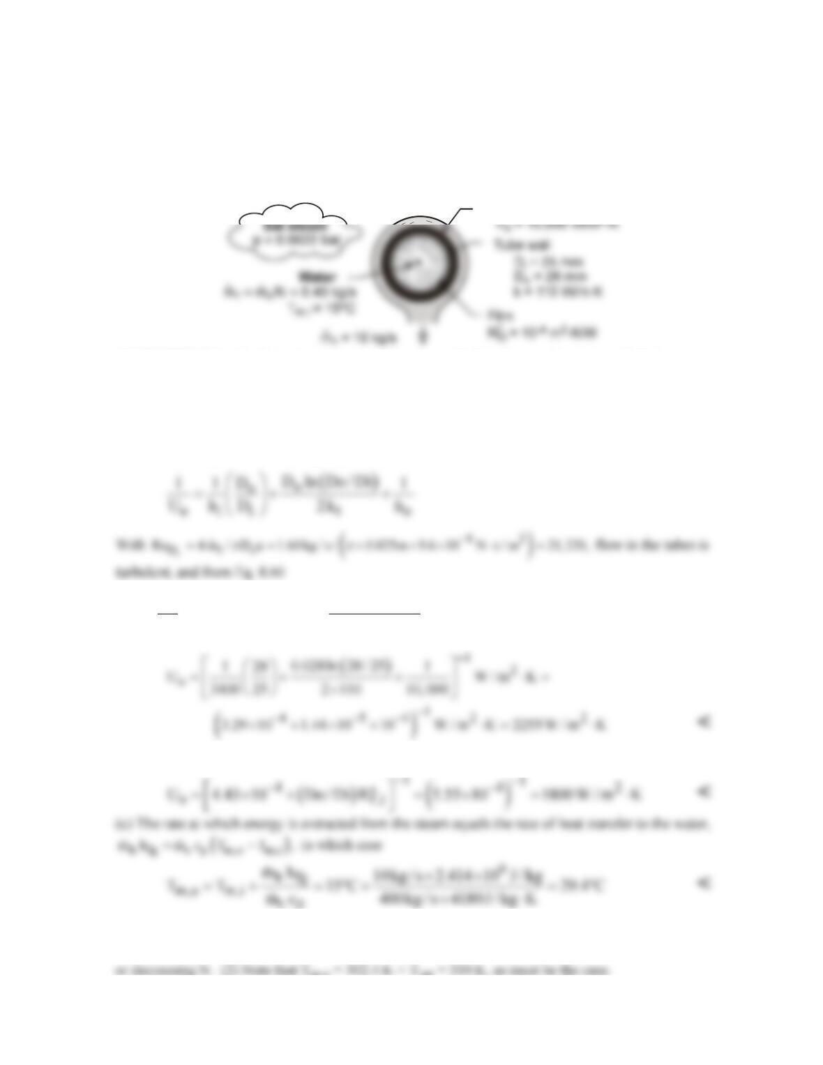
flow through the tubes. Flow rate and pressure of condensing steam. Fouling factor for inner surface.
FIND: (a) Overall coefficient based on outer surface area, Uo, without fouling, (b) Overall
coefficient with fouling, (c) Temperature of water leaving the condenser.
SCHEMATIC:
Condensate
ASSUMPTIONS: (1) Water is incompressible with negligible viscous dissipation, (2) Fully-
developed flow in tubes, (3) Negligible effect of fouling on Di.
PROPERTIES: Water (Given): cp = 4180 J/kg⋅K,
m
= 9.6 × 10⁻⁴ N⋅s/m2, k = 0.60 W/m⋅K, Pr = 6.6.
Table A-6, Water, saturated vapor (p = 0.0622 bars): Tsat = 310 K, hfg = 2.414 × 10⁶ J/kg.
ANALYSIS: (a) Without fouling, Eq. 11.5 yields
( ) ( )
i
4 / 5 0.4
4 / 5 0.4 2
iD
i
k 0.60 W / m K
h 0.023Re Pr 0.023 21, 200 6.6 3400 W / m K
D 0.025m
⋅
= = = ⋅
(b) With fouling, Eq. 11.5 yields
COMMENTS: (1) The largest contribution to the thermal resistance is due to convection at the
interior of the tube. To increase Uo, hi could be increased by increasing
1
m,
either by increasing
c
m
PROBLEM 11.6
KNOWN: Diameter and inner and outer convection coefficients of a condenser tube. Thickness, outer
diameter, and pitch of aluminum fins.
FIND: (a) Overall heat transfer coefficient without fins, (b) Effect of fin thickness and pitch on overall
heat transfer coefficient with fins.
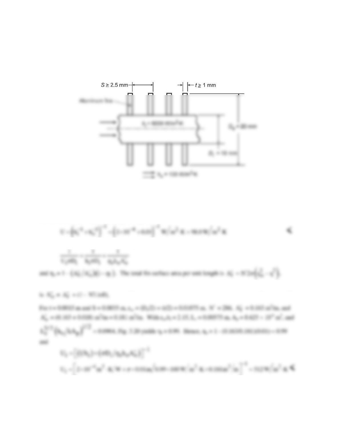
SCHEMATIC:
ASSUMPTIONS: (1) Negligible tube wall conduction resistance, (2) Negligible fouling and fin contact
resistance, (3) One-dimensional conduction in fin.
PROPERTIES: Table A.1, Aluminum (T = 300 K): k = 237 W/m⋅K.
ANALYSIS: (a) With no fins, Eq. 11.1 yields
(b) With fins and a unit tube length, Eqs. 11.1 and 11.3 yield
where the number of fins per unit length is
N 1m / S(m)
′=
. The total outside surface area per unit length
We may use the IHT Extended Surface Model (Performance Calculations for a Circular Rectangular Fin
Array) to consider the effect of varying t and S. To maximize
N′
, the minimum allowable value of
Continued…
PROBLEM 11.6 (Cont.)
S – t = 1.5 mm should be selected. It is then a matter of choosing between a large number of thin fins or a
smaller number of thicker fins. Calculations were performed for the following options.
t (mm)
S (mm)
¢
N
Ui (W/m2⋅K)
1
2.5
400
640
Since heat transfer increases with Ui, the best configuration corresponds to t = 1 mm and S = 2.5 mm,
which provides the largest airside surface area.
2
3.5
286
512
3
4.5
222
460
4
5.5
182
420
PROBLEM 11.7
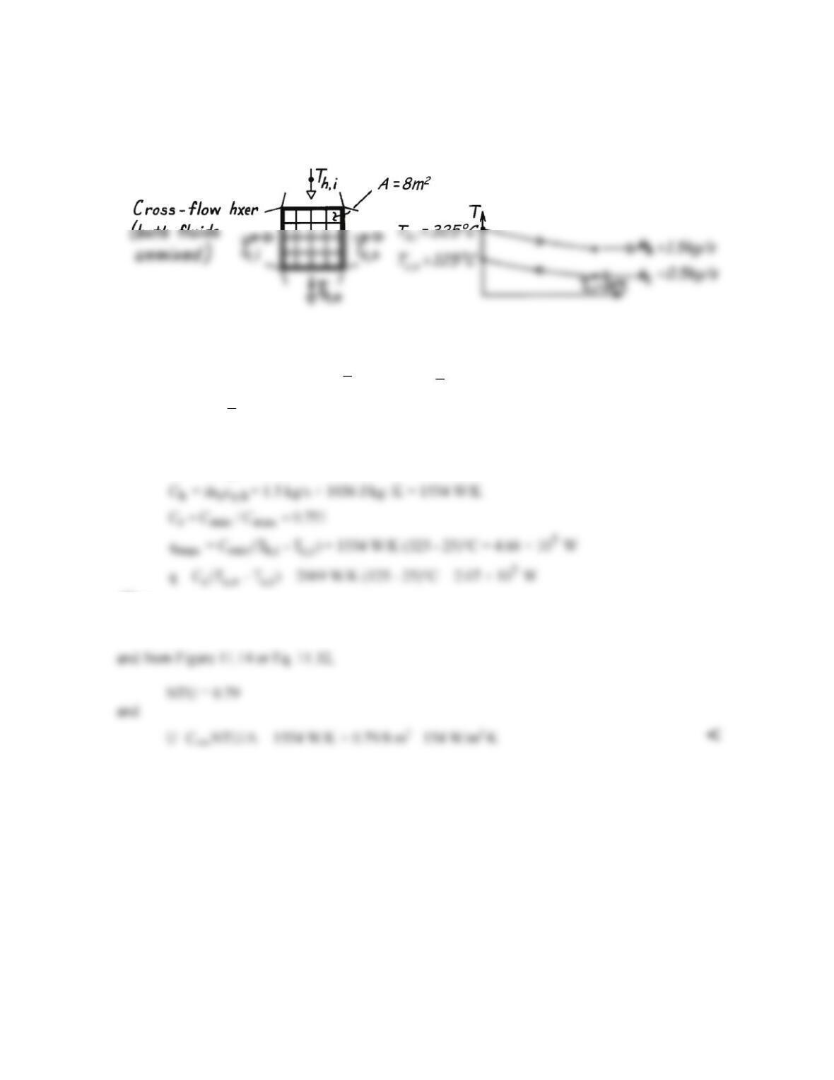
KNOWN: Operating conditions and surface area of a finned–tube, cross-flow exchanger.
FIND: Overall heat transfer coefficient.
SCHEMATIC:
ASSUMPTIONS: (1) Negligible heat loss to surroundings, (2) Constant properties, (3) Exhaust gas
properties are those of air.
PROPERTIES: Table A-6, Water
( )
m
T 75 C := °
p
c 4139 J / kg K;= ⋅
Table A-4, Air
( )
m
T 225 C :š
p
c 1036 J / kg K.= ⋅
ANALYSIS: Since this is a cross-flow heat exchanger, we will use the ε – NTU method, for which
c c p,c
C = m c = 0.5 kg/s × 4139 J/kg K = 2069 W/K⋅
C = m c = 1.5 kg/s × 1036 J/kg K = 1554 W/K⋅
Thus
max
q / q 0.444ε= =
COMMENTS: The hot outlet temperature is found from q = Ch (Th,i – Th,o) to be 192°C, thus
properties of the hot fluid should be evaluated at 259°C. Evaluation of cp for air at 255°C is
satisfactory since the specific heat does not vary significantly over this small temperature range.
PROBLEM 11.8
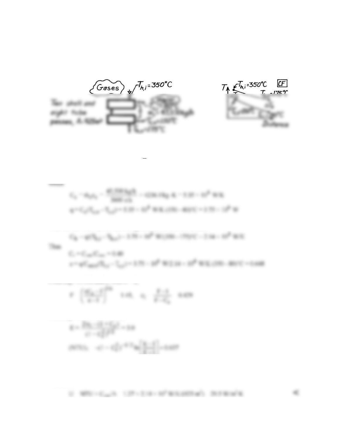
KNOWN: Heat exchanger with two shell passes and eight tube passes having an area 925m2; 45,500
kg/h water is heated from 80°C to 150°C; hot exhaust gases enter at 350°C and exit at 175°C.
FIND: Overall heat transfer coefficient.
SCHEMATIC:
ASSUMPTIONS: (1) Negligible losses to surroundings, (2) Constant properties, (3) Exhaust gas
properties are approximated as those of atmospheric air.
PROPERTIES: Table A-6, Water
( )
( )
c
T 80 150 C / 2 388K :=+°=
cc = cp,f = 4236 J/kg⋅K.
ANALYSIS: Since this is a shell-and-tube heat exchanger, we will use the ε – NTU method, for
Then we can find Ch from an energy balance on the hot stream,
From Eqs. 11.31b and c, with n = 2,
From Eqs. 11.30c and 11.30b,
E1
+
and from Eq. 11.31d,
NTU = n(NTU)1 = 1.27
Therefore,
COMMENTS: Compare the above result with representative values for air–water exchangers, as
given in Table 11.2.
PROBLEM 11.9
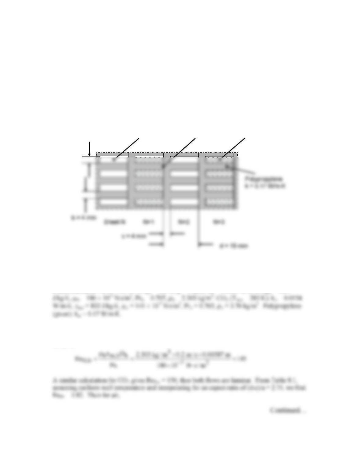
KNOWN: Geometry of heat exchanger made from extruded polypropylene sheets. Thermal
conductivity of polypropylene. Temperature, pressure, and velocity, of air and carbon dioxide
flowing in channels.
FIND: Product of overall heat transfer coefficient and surface area, UA, for 200 cool and 200
warm channels.
SCHEMATIC:
ASSUMPTIONS: (1) Constant properties and steady-state conditions, (2) Density of air and
CO2 is proportional to pressure, (3) Wall temperature is approximately uniform along channels,
(4) Thermal resistance at welded interface is negligible, (5) Channel walls can be treated as fins.
PROPERTIES: Table A.5, Air: (Tm,h = 303 K, p = 2 atm): kh = 0.0265 W/m⋅K, cp,h = 1007
ANALYSIS: We begin by finding the heat transfer coefficients for air and CO2. In both cases,
the hydraulic diameter is Dh = 4Ac/P = 4×11×4/(2(11+4) mm = 5.87 mm. The Reynolds number
for air is
CO
2
T
m,c
= 10°C, p = 2 atm
u
m
= 0.1 m/s Welded Interface
a = 4 mm
Air
T
m,h
= 30°C, p = 2 atm
u
m
= 0.2 m/s
CO
2
T
m,c
= 10°C, p = 2 atm
u
m
= 0.1 m/s Welded Interface
a = 4 mm
Air
T
m,h
= 30°C, p = 2 atm
u
m
= 0.2 m/s
PROBLEM 11.9 (Cont.)
2
h D,h h h
h Nu k / D 3.82 0.0265 W / m K / 0.00587 m 17.2 W/m K= =×⋅ =⋅
And a similar calculation for CO2 yields hc = 10.0 W/m2⋅K.
Focusing on one vertical wall of thickness c in the schematic above, we see that it has fins
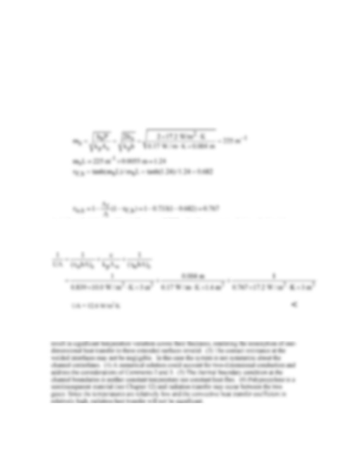
extending to the right and left into the two fluids. By symmetry, the midpoint of those fins is an
adiabat, and we can treat the fins as having length L = (d–c)/2 = 5.5 mm, with an insulated tip.
We will use Eq. 11.1 for UA, with Eqs. 11.3 and 11.4 for the fin efficiency. Note that for
channels of length w, P/Ac = 2(w+b)/wb ≈ 2/b. For air,
Then Af/A = 2L/(2L + a) = 0.733 and
A similar calculation for CO2 yields
o,c
0.839h=
. Finally, we use Eq. 11.1 to calculate UA.
Note that for N = 200 channels (and N fins) of depth w, A = 2LwN + awN = 3w m2 and Aw =
(a+b)wN = 1.6w m2. Thus, for a unit length of the heat exchanger (w = 1 m),
COMMENTS: (1) The product of the overall heat transfer coefficient and the heat transfer area
is not large, but the design enables production of a compact heat exchanger that is not prone to
corrosion and can be constructed at low cost. (2) The low thermal conductivity of the “fins” may
PROBLEM 11.10
KNOWN: Properties and flow rates for the hot and cold fluid of a heat exchanger.
FIND: Which fluid limits the heat transfer rate of the heat exchanger.
ASSUMPTIONS: (1) Steady-state conditions, (2) Constant properties, and (3) Negligible losses to
the surroundings.
ANALYSIS: The properties and flow rates for the hot and cold fluid of the heat exchanger are
tabulated below.
Cold fluid Hot fluid
Density, kg/m3 997 1247
For the hot and cold fluids,
( )
33
h hh
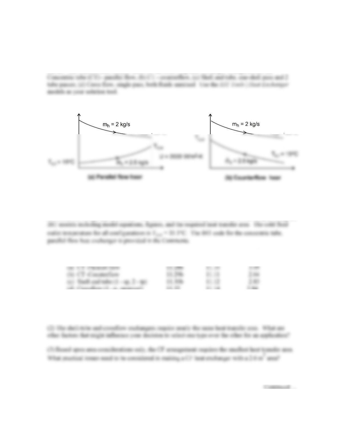
C m c 18 m / h 1247 kg/m 2564 J/kg K 1h/3600s 15.99 kW/K= = × × ⋅× =
Hence, the cold fluid has the minimum heat capacity rate,
min c
CC=
For any exchanger, the heat rate is q = ε qmax, where ε depends upon the exchanger type. The
PROBLEM 11.11
KNOWN: Process (hot) fluid having a specific heat of 3500 J/kg⋅K and flowing at 2 kg/s is to be
cooled from 80°C to 50°C with chilled–water (cold fluid) supplied at 2.5 ks/g and 15°C assuming an
overall heat transfer coefficient of 2000 W/m2⋅K.
FIND: The required heat transfer areas for the following heat exchanger configurations; (a)
SCHEMATIC:
T = 80 C
h,i o
.
T = 50 C
T = 80 C
h,i o
.
T = 50 C
ASSUMPTIONS: (1) Steady-state conditions, (2) Negligible losses to the surroundings, (3) Overall
heat transfer coefficient remains constant with different configurations, and (4) Constant properties.
ANALYSIS: The IHT Tools | Heat Exchanger models are based upon the effectiveness–NTU method
and suited for design-type problems. The table below summarizes the results of our analysis using the
Heat exchanger type Eqs. Figs A(m2)
(d) Crossflow (1 – p, unmixed) 11.32 11.14 2.84
COMMENTS: (1) Referring to the tabulated results, note that for the concentric tube exchangers,
the area required for parallel flow is 17% larger than for counterflow. Under what circumstances
would you choose to use the PF arrangement if the area has to be significantly larger?
PROBLEM 11.11 (Cont.)
(4) The IHT code used for the concentric tube, parallel flow heat exchanger is shown below. Note the
use of the water property function, cp_Tx, and the intrinsic function, Tfluid_avg, to provide the
specific heat at the mean water (cold fluid) temperature.
/” Results – energy balance only
// Design conditions
Thi = 80
Tho = 50
// For the parallel–flow, concentric–tube heat exchanger,
// For the parallel–flow, concentric–tube heat exchanger,
NTU = –ln(1 – eps * (1 + Cr))/(1 + Cr) // Eq 11.28b
// where the heat–capacity ratio is
// Energy balances
q = Cc * (Tco – Tci)
// Water property functions: T dependence, From Table A.6
// Units: T(K), p(bars):
xc = 0 // Quality (0=sat liquid or 1–sat vapor)
PROBLEM 11.12
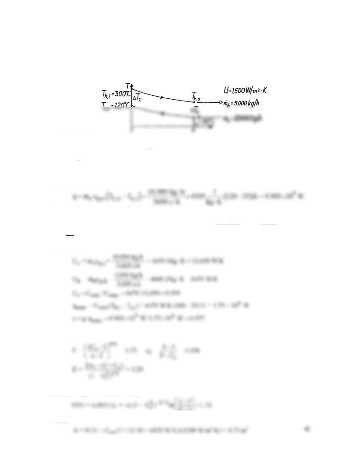
KNOWN: A shell and tube Hxer (two shells, four tube passes) heats 10,000 kg/h of pressurized
water from 35°C to 120°C with 5,000 kg/h water entering at 300°C.
FIND: Required heat transfer area, As.
SCHEMATIC:
ASSUMPTIONS: (1) Negligible heat loss to surroundings, (2) Constant properties.
PROPERTIES: Table A-6, Water
( )
c
T 350 K :=
cp = 4195 J/kg⋅K; Table A-6, Water (Assume Th,o
≈ 150°C,
h
T
≈ 500 K): cp = 4660 J/kg⋅K.
ANALYSIS: For a shell and tube heat exchanger, we use the ε – NTU method. An energy balance
on the cold fluid yields
An energy balance on the hot fluid yields
5
h,o h,i h p,h
5000 kg J
T T q / m c 300 C 9.905 10 W / 4660 147 C.
3600 s kg K
= − = °− × × = °
⋅
Thus
h
T = (300 + 147)°C/2 = 497 K
is the proper temperature for evaluating properties of the hot
fluid. Then
From Eqs. 11.31c, 11.31b, and 11.30c, with n =2,
then from Eqs. 11.30b and 11.31d,
E1
+
Finally,