PROBLEM 11.58
KNOWN: Rankine cycle with saturated steam leaving the boiler at 2 MPa and a condenser pressure
of 10 kPa. Net reversible work of 0.5 MW.
FIND: (a) Thermal efficiency of ideal Rankine cycle, (b) Required cooling water flow rate to
condenser at 15°C with allowable temperature rise of 10°C, and (c) Design of a shell and tube heat
exchanger (one shell and multiple tube passes) to satisfy condenser flow rate and temperature rise.
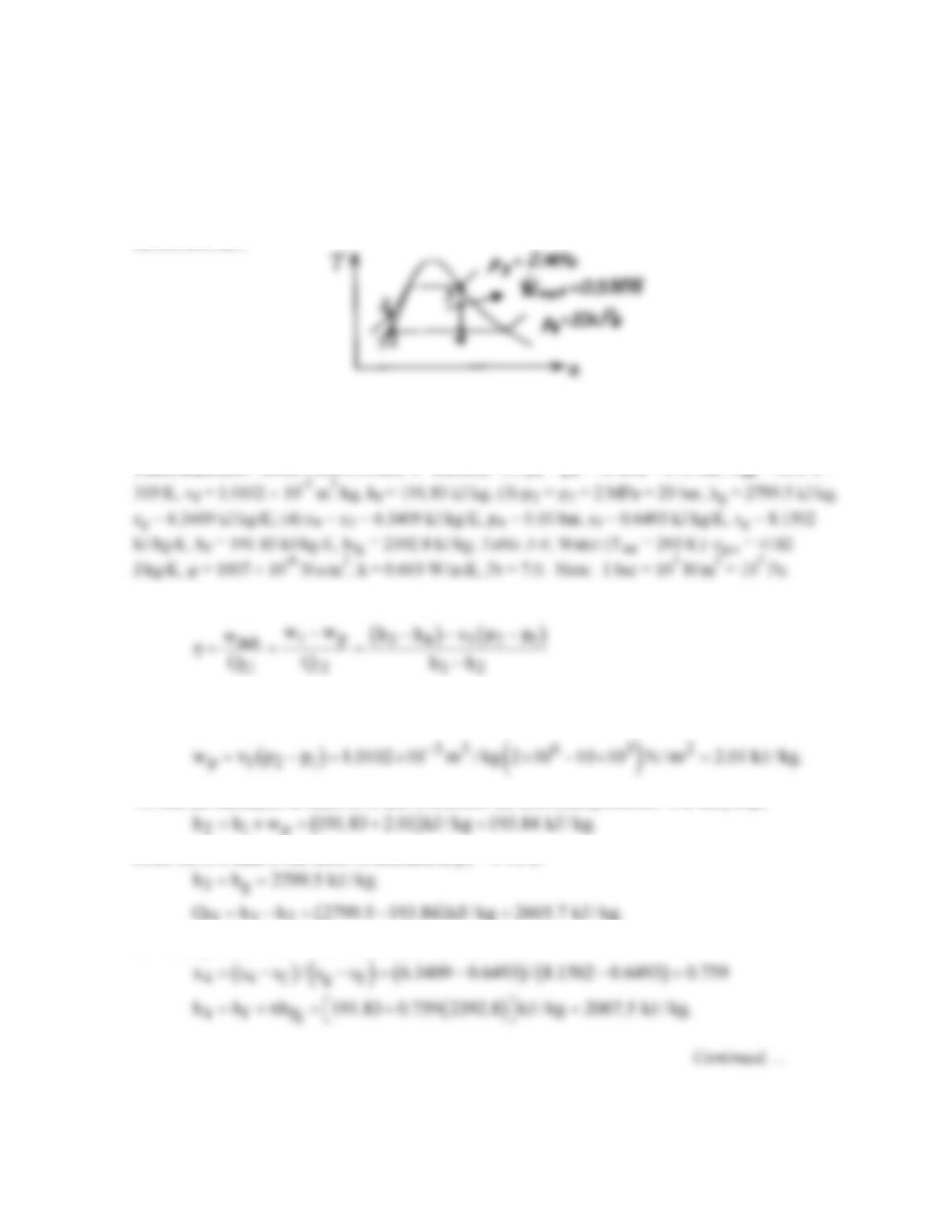
SCHEMATIC:
ASSUMPTIONS: (1) Negligible loss from condenser to surroundings, (2) Ideal Rankine cycle, and
(3) Negligible thermal resistance on condensate side of exchanger tubes.
PROPERTIES: Steam Tables, (Wark, 4th Edition): (1) p1 = p4 = 10 kPa = 0.10 bar, Tsat = 45.8°C =
ANALYSIS: (a) Referring to Chapter 1 and your thermodynamics text, find that
where the net work is the turbine minus the pump work. Assuming the liquid in the pump is
incompressible,
To find the enthalpies at states 2, 3, and 4, consider the individual processes. For the pump,
Since the exit state of the boiler is saturated at p3 = 2 MPa,
H 32
Since the process from 3 to 4 is isentropic, s4 – s3, hence
PROBLEM 11.58 (Cont.)
(b) From an overall balance on the cycle, the heat rejected to the condenser is
( )
c H net
Q Q w 2605.7 792.0 2.01 kJ / kg 1815.7 kJ / kg.
=−= − − =
Since the net reversible power is 0.5 MW, the required steam rate (h) is
Hence, the heat rate to be removed by the cold water passing through the condenser is
where cp,c = cp,f is evaluated at T2, Tc,in = 15°C and Tc,out – Tc,in = 10°C, the specified allowable
rise.
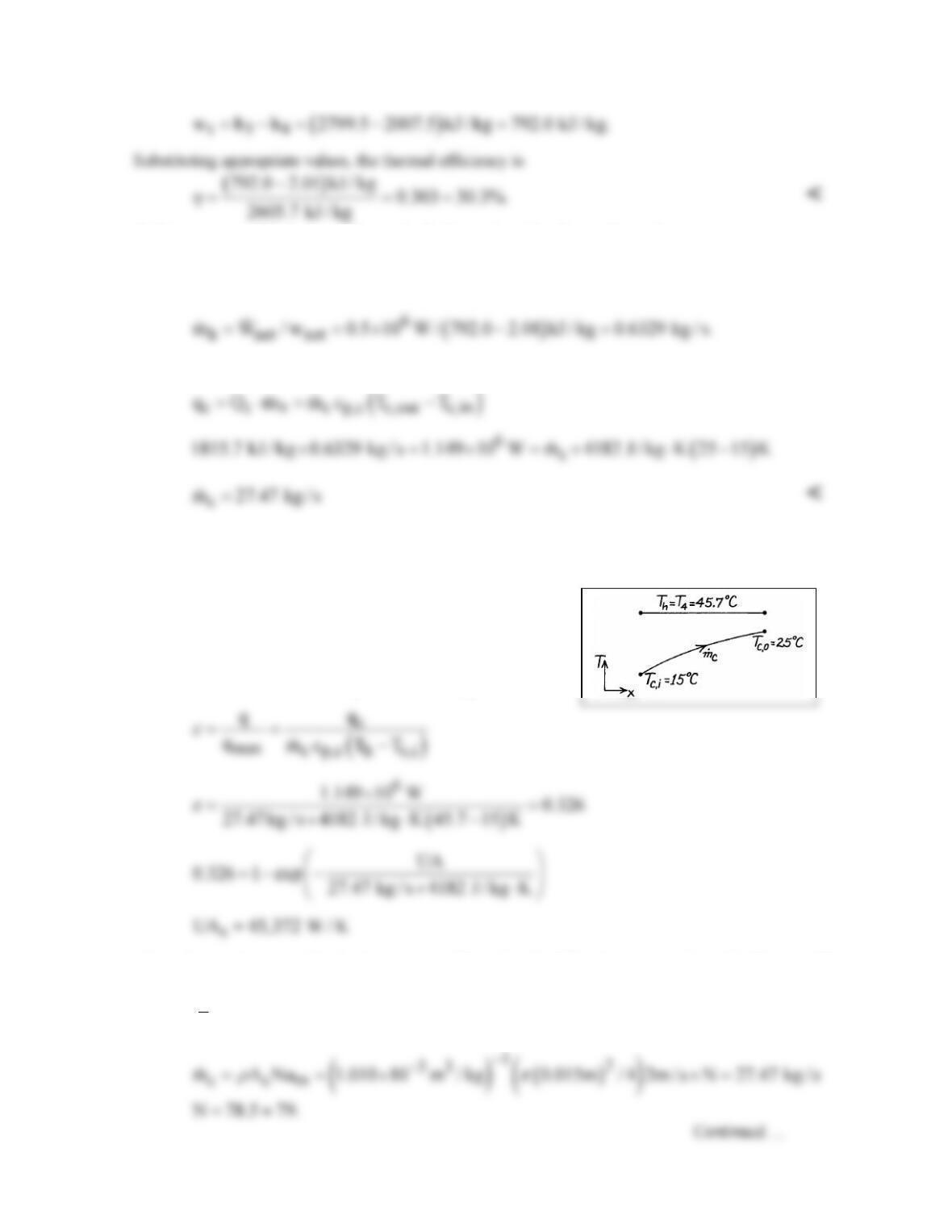
(c) To design the heat exchanger we need to
evaluate UA. Considering the shell–tube
configuration and since Cr = Cmin/Cmax = 0,
( ) ( )
min
1 exp NTU 1 exp UA / C
ε
=−− =−−
where Cmin =
c p,c
mc .
Our design process will involve the following steps: select tube diameter, D
= 15 mm; set um = 2 m/s in each tube and find number of tubes; perform internal flow calculation to
estimate
c
h
and then determine the length.
PROBLEM 11.58 (Cont.)
For flow in a single tube,
Assuming the flow is fully developed and using the Dittus-Boelter correlation,
Hence, the tube length is
and our design has the following parameters:
N 79 tubes L 1.6m D 15 mm.= = =
<
COMMENTS: (1) The selection of the tube diameter and water velocity values (15 mm, 2 m/s) was
based upon prior experience; they seemed reasonable. We could, however, establish other
requirements which would influence these choices such as allowable pressure drop and standard tube
sizes.
PROBLEM 11.59
KNOWN: Rankine cycle with saturated steam leaving the boiler at 2 MPa and a condenser pressure
of 10 kPa. Heat rejected to the condenser of 2.3 MW. Condenser supplied with cooling water at rate
of 70 kg/s at 15°C.
FIND: (a) Size of the condenser as determined by the parameter, UA, and (b) Reduction in thermal
efficiency of the cycle if U decreases by 10% due to fouling assuming water flow rate and inlet
temperature and the condenser steam pressure remain fixed.
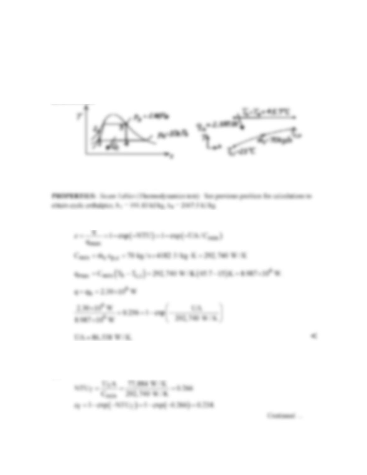
SCHEMATIC:
ASSUMPTIONS: (1) Negligible loss from condenser to surroundings, (2) Ideal Rankine cycle, (3)
For fouled operating condition,
c, c,i
mT
and p4 remain the same.
ANALYSIS: (a) For the condenser, recognize that Cmin = Cc, and Cr = Cmin/Cmax = 0,
(b) In the fouled condition, U is reduced 10%, hence
f
U A 0.9 UA 77,884 W / K= =
and
PROBLEM 11.59 (Cont.)
If we operate the cycle at the same back pressure p4 = 10 kPa so that Th = 45.7°C, the heat removal
rate must decrease,
since qmax = Cmin (Th – Tc,i) remains the same. From the previous problem, we found the heat
rejected as
and hence the cycle steam rate through the fouled condenser is
For the unfouled condenser of part (a), the steam rate was
Hence, we see that fouling reduces the steam rate by 8.5% when U is decreased 10%. Since p4
remains the same, the thermal efficiency remains unchanged,
COMMENTS: Fouling of the condenser heat exchanger has no effect on the thermal efficiency of
the cycle since the back pressure at the condenser is maintained constant. The effect is, however, to
reduce the heat rejection rate while maintaining exchanger flow rate and inlet temperature fixed.
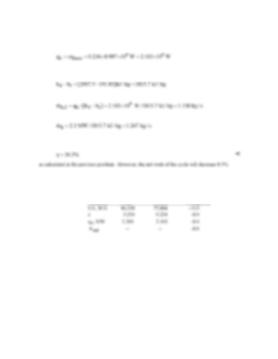
Comparing the conditions:
Parameter Clean Fouled Change (%)
PROBLEM 11.60
KNOWN: Inlet and outlet temperatures for a shell-and-tube heat exchanger with two shells,
each with 10 tubes making eight passes. Heat transfer coefficient for oil flowing in shell. Mass
flow rate of water in tubes. Tube diameter.
FIND: Is the required tube length sufficiently small to fit in an 8 m long facility, if the floor
space must be at least 2.5 times the length of the heat exchanger?
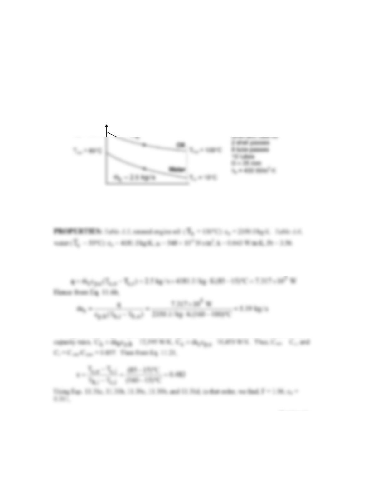
SCHEMATIC:
T = 100 C
.
ASSUMPTIONS: (1) Negligible heat loss to the surroundings, (2) Constant properties, (3)
Negligible tube wall thermal resistance and fouling effects, (4) Fully developed water flow in
tubes.
ANALYSIS: From the overall energy balance, Eq. 11.7b, the heat transfer required of
the exchanger is
The required tube length may be obtained using the ε–NTU method. We first calculate the heat
Continued…
T
h,i
= 160°C
h
T
T
= 15°C
PROBLEM 11.60 (Cont.)
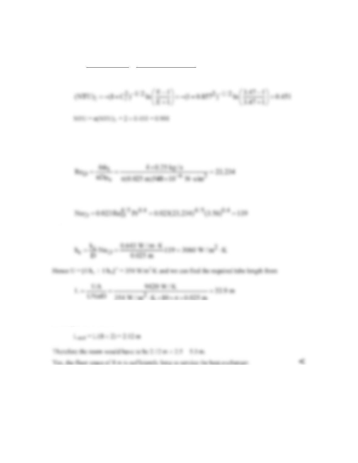
1r
2 1/2 2 1/2
r
2 / (1 C ) 2 / 0.311 (1 0.857)
E 3.47
(1 C ) (1 0.857 )
ε−+ −+
= = =
++
Thus UA = NTU×Cmin = 9420 W/K. To find the required tube length, we must know the heat
transfer coefficient for the water flow. We calculate the Reynolds number from Eq. 8.6, with the
water flow rate per tube as
1c
m m /N=
= 0.25 kg/s,
Hence the flow is turbulent, and from Eq. 8.60,
and
This is the total tube length for all ten tubes in both shells, therefore the length of the heat
exchanger shell must be
Yes, the floor space of 8 m is sufficiently long to service the heat exchanger. <
COMMENTS: (1) With L/D = 33.9/0.025 = 1356, the assumption of fully developed
conditions throughout the tube is justified. (2) The floor–to–ceiling height must be sufficiently
large to stack one shell above the other.
PROBLEM 11.61
KNOWN: Configuration of a cubical plate–type heat exchanger with 40 gaps. Fluid flow rates,
inlet temperatures, and desired oil outlet temperature.
FIND: (a) Core dimension, L, of the heat exchanger, when the sheet thickness is 0.8 mm, for
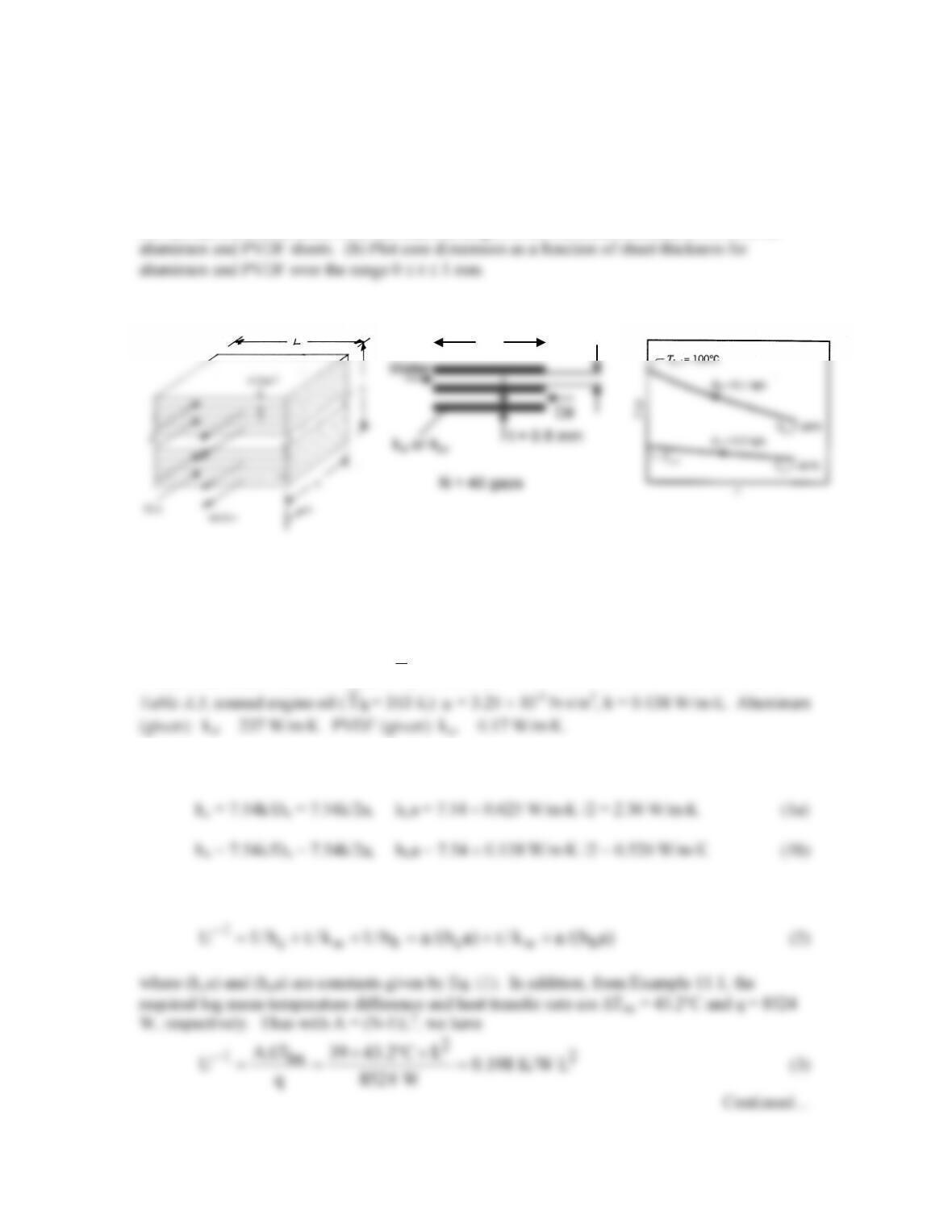
SCHEMATIC:
t = 0.8 mm
ASSUMPTIONS: (1) Negligible heat loss to the surroundings, (2) Constant properties, (3)
Negligible fouling factors, (4) Laminar, fully developed conditions for the water and oil, (5)
Identical gap–to–gap heat transfer coefficients. (6) Heat exchanger exterior dimension is large
compared to the gap width.
PROPERTIES: Table A.6, water (
c
T
≈ 35°C): µ = 725 × 10–6 N⋅s/m2, k = 0.625 W/m⋅K.
ANALYSIS: (a) From Example 11.2, assuming the flow is still laminar,
and the overall convection coefficient, including the wall thermal resistance, is given by
L
a
PROBLEM 11.61 (Cont.)
The core dimension, L, is related to the gap dimension, a, and sheet thickness, t, (neglecting the
exterior plates) by the expression
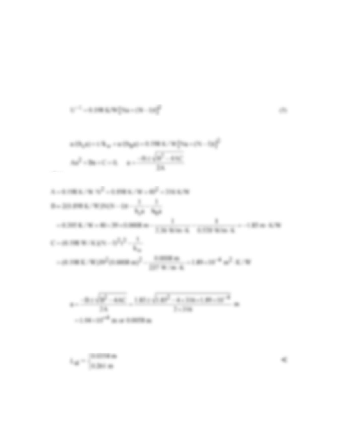
L = Na + (N–1)t (4)
Thus, Eq. (3) becomes
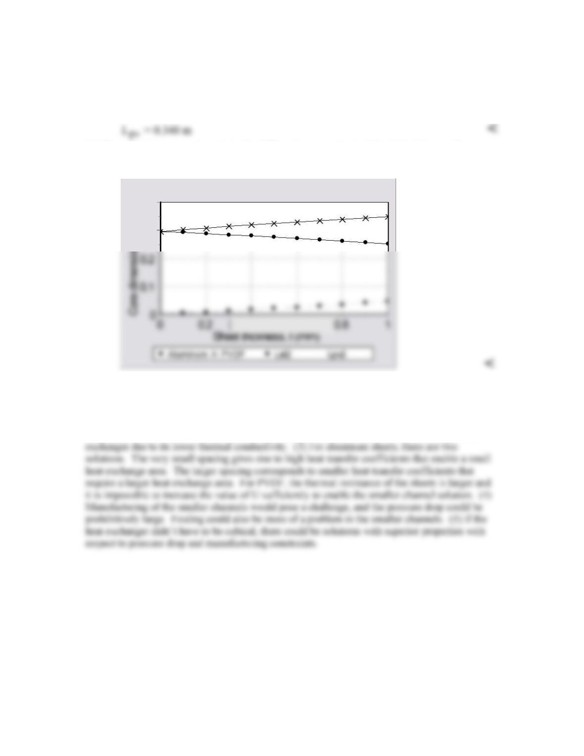
Equating Eqs. (2) and (5), we can solve the resulting quadratic equation for a,
where
We have used kw = kal in evaluating C. Thus
See the Comments for a discussion of the two different solutions. Hence from Eq. (4), when the
sheets are aluminum,
Continued…
PROBLEM 11.61 (Cont.)
Repeating the calculations for PVDF, we find only one (positive) solution, a = 0.00771 m, for
which
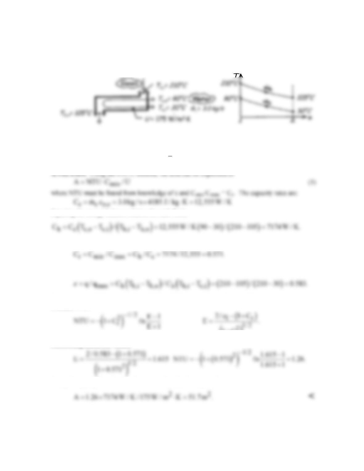
(b) The calculations were keyed into the IHT workspace and solved for 0 ≤ t ≤ 1 mm. The
solution is shown below for aluminum and PVDF sheets.
0.4
0.3
COMMENTS: (1) We can check the Reynolds number to see if the flow is truly laminar. The
largest Reynolds number would be for water, since it is less viscous and has a higher flow rate.
Thus Re =
1
4m / Pm≈
4m/(N/2)/2 L
m
. For the smaller value of L, Re = 779. Hence the flow
is laminar for both oil and water. (2) As expected, utilization of PVDF results in a larger heat
PROBLEM 11.62
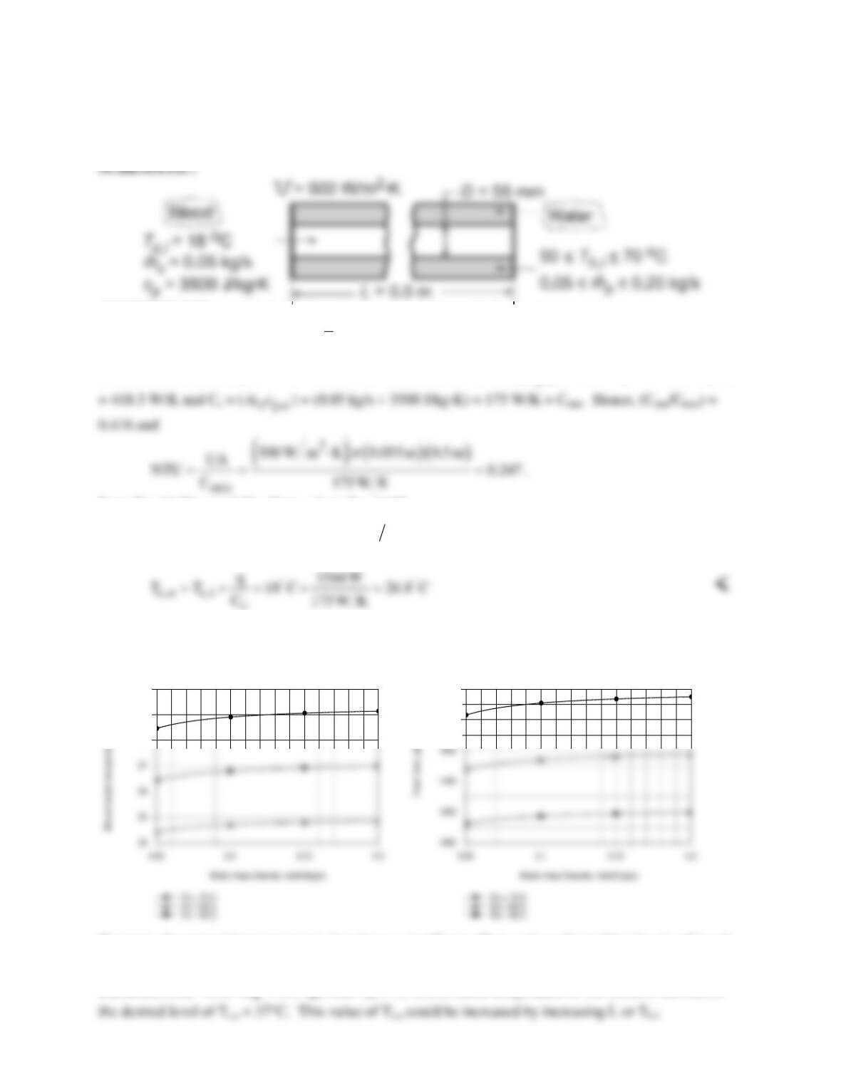
KNOWN: Shell and tube heat exchanger for cooling exhaust gases with water.
FIND: Required surface area using ε–NTU method.
SCHEMATIC:
ASSUMPTIONS: (1) Negligible heat loss to surroundings, (2) Constant properties, (3) Gases have
properties of air.
PROPERTIES: Table A-6, Water, liquid (
c
T
= (90 + 30)°C/2 = 333 K): cp = 4185 J/kg⋅K.
Equating the energy balance relation for each fluid,
Hence,
The effectiveness of the exchanger, with qmax = Cmin (Th,i – Tc,i) and Cmin = Ch, is
Considering the HXer to be a single shell with 2,4….tube passes, Eqs. 11.30b,c are appropriate to
evaluate NTU.
()
2
r
Substituting numerical values,
Using the appropriate numerical values in Eq. (1), the required area is
COMMENTS: Figure 11.12 could also have been used with Cr and ε to find NTU.
PROBLEM 11.63
KNOWN: Dimensions, fluid flow rates, and fluid temperatures for a counterflow heat exchanger used to
heat blood.
FIND: (a) Outlet temperature of the blood, (b) Effect of water flowrate and inlet temperature on heat
rate and blood outlet temperature.
ASSUMPTIONS: (1) Negligible heat loss to surroundings, (2) Constant properties.
PROPERTIES: Table A.6, Water (
m
T
≈ 55°C): cp = 4183 J/kg⋅K.
ANALYSIS: (a) Using the ε – NTU method, we first obtain Ch = (
h p,h
mc
) = (0.10 kg/s × 4183 J/kg⋅K)
From Eq. 11.29a, ε = 0.21. Hence, from Eq. 11.22
( )
( )( )
min h,i c,i
q C T T 0.21 175 W K 60 18 C 1544 W
ε
= −= − =
.
From Eq. 11.7b,
(b) Because the variation of Cmin/Cmax with
h
m
does not have a significant effect on ε for the prescribed
NTU, Tc,o and q increase only slightly with increasing
h
m
.
28
29
30
1800
2000
However, the water inlet temperature does have a significant effect, and accelerated heating is achieved
with Th,i = 70°C.
COMMENTS: With
m
= 0.2 kg/s and Th,i = 70°C, the outlet temperature of the blood is still below
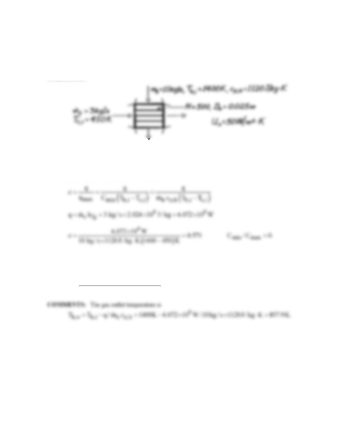
PROBLEM 11.64
KNOWN: Flow rate, specific heat and inlet temperature of gas in cross–flow heat exchanger. Flow
rate and temperature of water which enters as saturated liquid and leaves as saturated vapor. Number
of tubes, tube diameter and overall heat transfer coefficient.
FIND: Required tube length.
SCHEMATIC:
ASSUMPTIONS: (1) Negligible heat loss to surroundings, (2) Constant gas specific heat.
PROPERTIES: Table A-6, Saturated Water, (T = 450 K): hfg = 2.024 ×10⁶ J/kg.
ANALYSIS: Use effectiveness–NTU method
From Fig. 11.15, find
o o min
NTU 0.8 U N D L / C
p
≈≈
2
0.8 10 kg / s 1120 J / kg K
L 4.56m.
50 W / m K 500 0.025m
p
×× ⋅
≈=
⋅× ×
<
PROBLEM 11.65
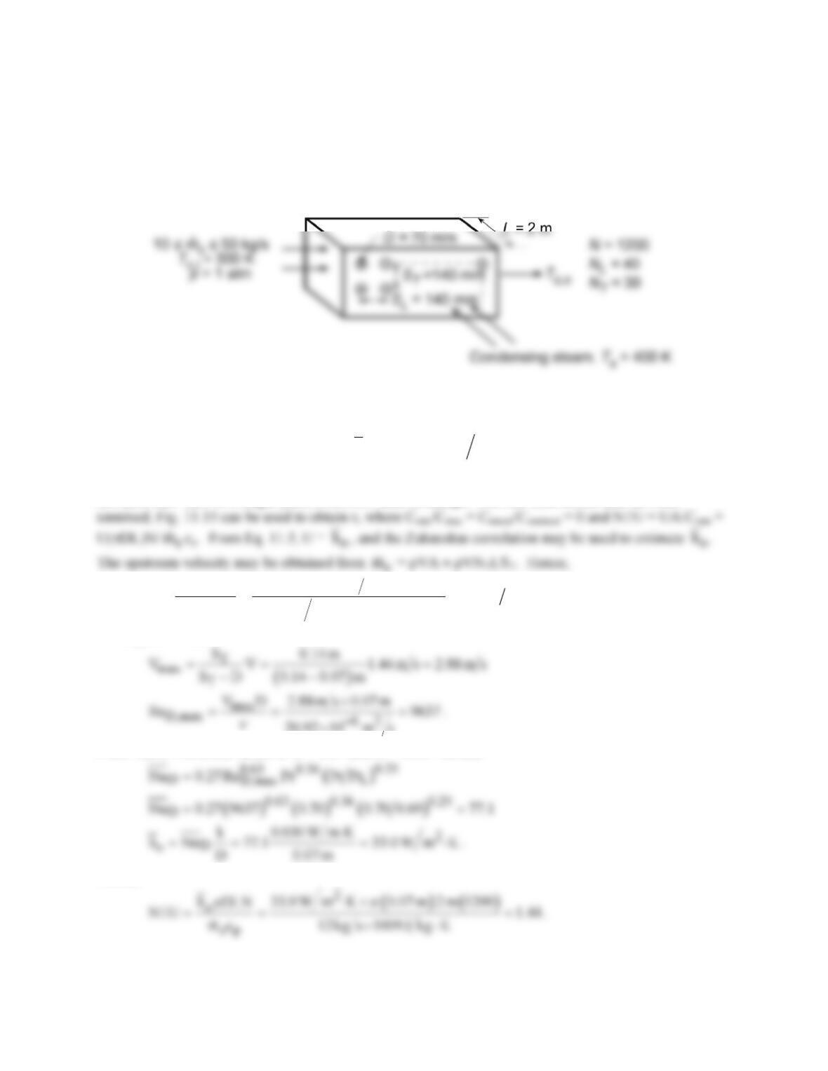
KNOWN: Tube arrangement in steam–to–air, cross–flow heat exchanger. Flow rate
c
m
and inlet
temperature of air. Condensing temperature of steam.
FIND: (a) Air outlet temperature for
mc
= 12 kg/s, (b) Effect of
c
m
on air outlet temperature, heat rate
and condensation rate.
SCHEMATIC:
ASSUMPTIONS: (1) Negligible heat loss to surroundings, (2) Negligible steam side convection and
tube wall conduction resistance, (3) Mean air temperature is 350 K.
PROPERTIES: Table A.4, Air (Assume
( )
c c,i c,o
TTT 2≡+
≈ 350 K, 1 atm): ρ = 0.995 kg/m3, cp =
1009 J/kg⋅K, ν = 20.92 × 10⁻⁶ m2/s, k = 0.030 W/m⋅K, Pr = 0.700; Ts = 400 K: Pr = 0.690.
ANALYSIS: (a) For a single–pass, cross–flow heat exchanger with one fluid mixed and the other
c
m
c
m
c
3
TT
m12 kg s
V 1.44 m s
N LS 0.995 kg m 30 2 m 0.14 m
ρ
= = =
×× ×
.
For aligned tubes,
20.92 10 m s
×
From Table 7.5, select values of C = 0.27 and m = 0.63. Hence,
Hence,
From Fig. 11.15, find ε ≈ 0.77 and then determine
Continued…
PROBLEM 11.65 (Cont.)
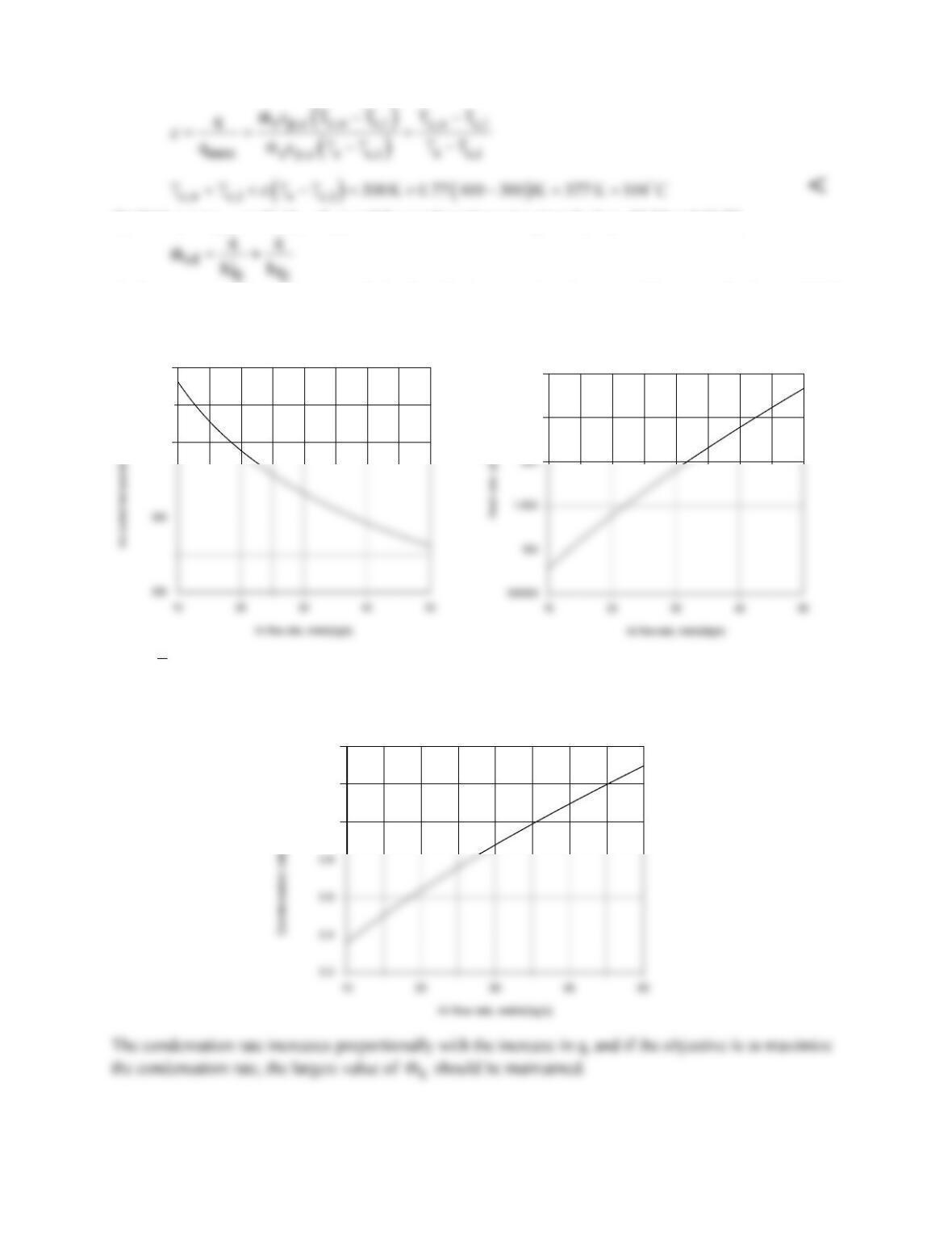
(b) With q = εqmax = εCc(Ts – Tc,i) and the condensation rate given by Eqs. 10.34 and 10.27,
the foregoing model may be used with the Heat Exchangers, Correlations and Properties Toolpads of IHT
to determine the effect of
mc
on Tc,o, q and
cd
m
.
370
380
2.5E6
3E6
Since
o
h
increases with increasing
c
m
, q must also increase. However, since the increase in q is
proportionally less than the increase in
c
m
, Tc,o decreases with increasing
c
m
.
1
1.2
1.4
COMMENTS: If the objective is to heat the air, there is obviously a trade–off between maintaining
elevated values of the flow rate and outlet temperature.
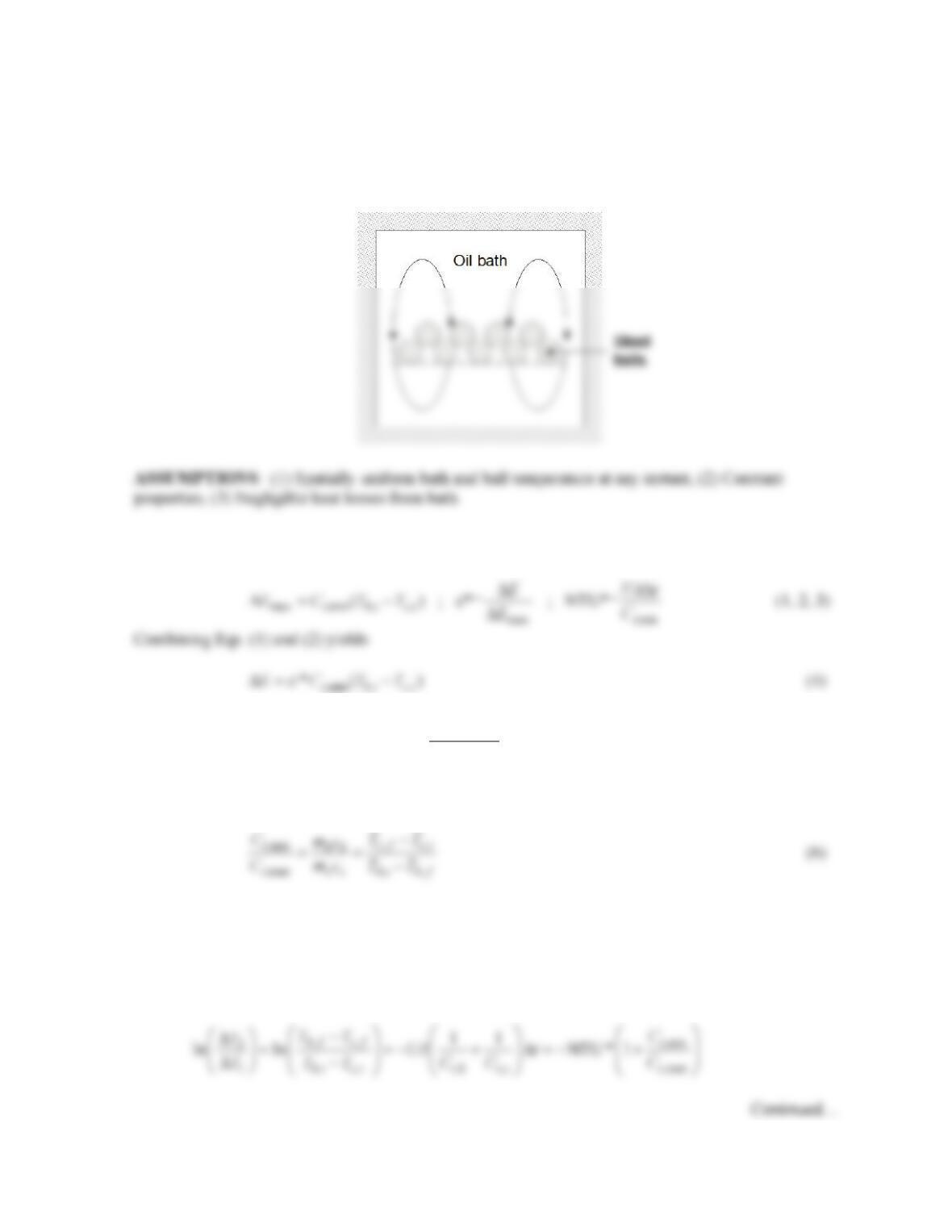
PROBLEM 11.66
KNOWN: Steel balls cooled in an oil bath.
FIND: Derivation of the expression for the modified effectiveness of Comment 4 of Example 11.8.
SCHEMATIC:
ANALYSIS: From Comment 4 of Example 11.8,
Assuming Ct,min = Ct,h, it follows that
,,
,,
*
hi h f
hi ci
TT
TT
ε
−
=−
(5)
and therefore,
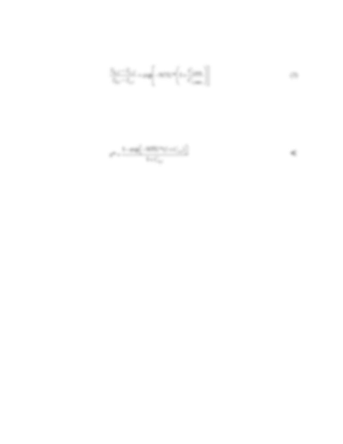
Note that Eqs. (1) through (6) are analogous to Eqs. 11.18, 11.19, 11.24, 11.22, 11.25 and 11.26 in the
text.
From Comment 3 of Example 11.8,
Problem 11.66 (Cont.)
or
Equation (7) is identical in form to Eq. 11.27 in the text.
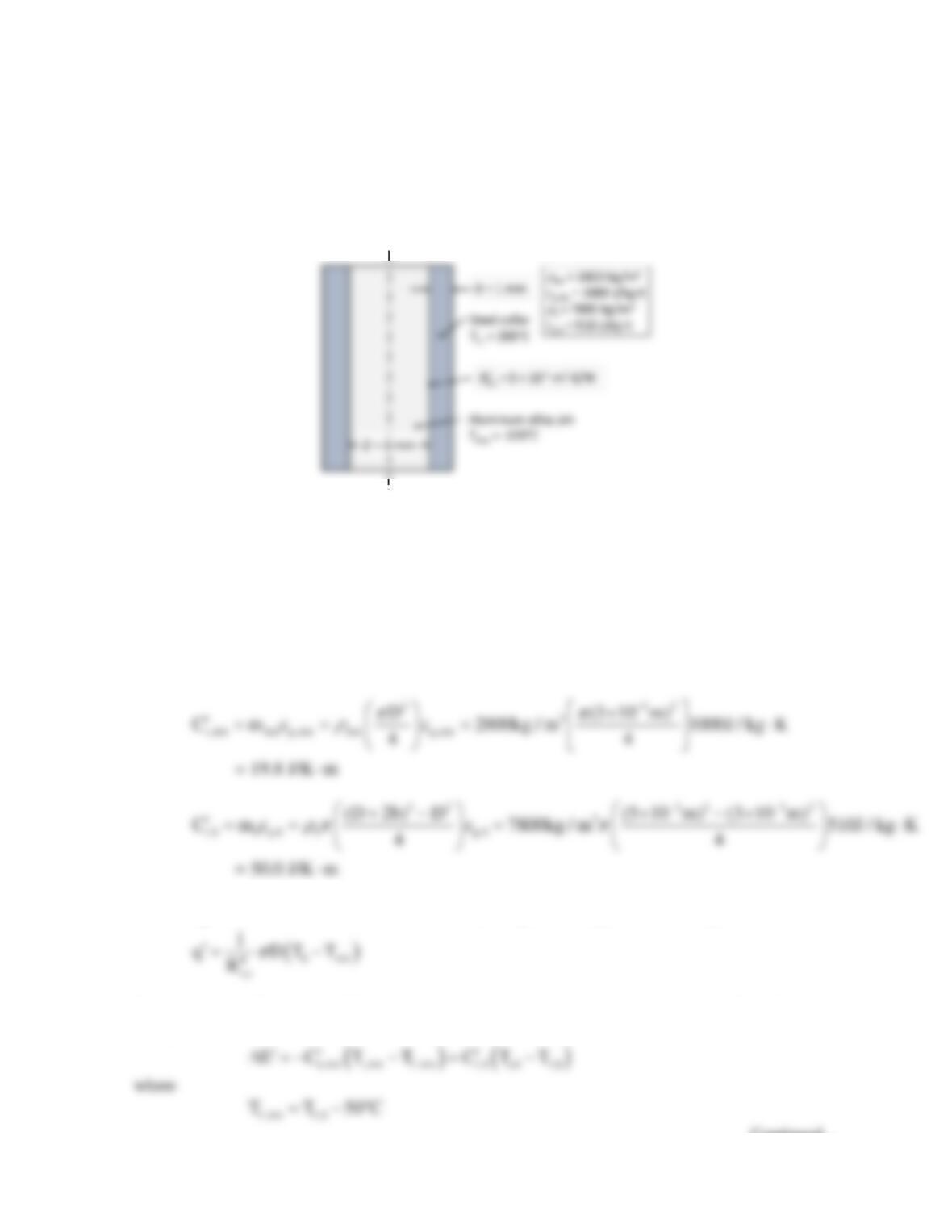
Noting the analogy between Eqs.(1) through (7) with the equations in the text, we may proceed in a
manner identical to that of the text, after Equation 11.27, obtaining
COMMENTS: The derivation is straightforward, once the analogy between the parallel–flow
concentric tube heat exchanger analysis is recognized.
PROBLEM 11.67
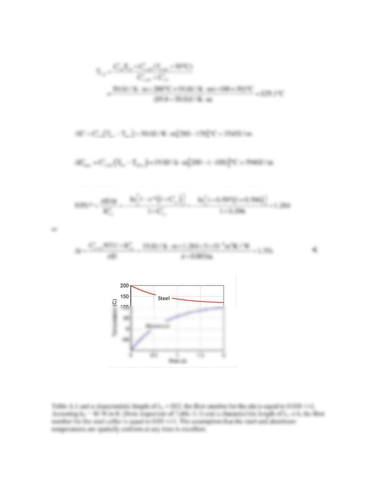
KNOWN: Dimensions, properties, and initial temperatures of steel collar and aluminum alloy pin.
Thermal contact resistance between collar and pin.
FIND: Time needed to decrease temperature difference between collar and pin to 50°C. Plot of steel
and aluminum temperatures over a total time of 2s.
SCHEMATIC:
ASSUMPTIONS: (1) Spatially uniform collar and pin temperatures at any time, (2) Constant
properties, (3) Negligible heat losses to, or heat gains from the environment, (4) Collar and pin are
long.
PROPERTIES: See schematic.
ANALYSIS: The thermal capacitance per unit length of the pin and collar are:
So that
t,r
C 19.8 / 50.0 0.396
′= =
and the heat transfer per unit length between the pin and collar is
Proceeding as in Comment 4 of Example 11.8, the energy change per unit length to the final (f) time
of interest is
Continued…
PROBLEM 11.67 (Cont.)
Combining the two preceding equations yields
so that the energy exchange per unit length over the time of interest is
The maximum possible energy exchange is
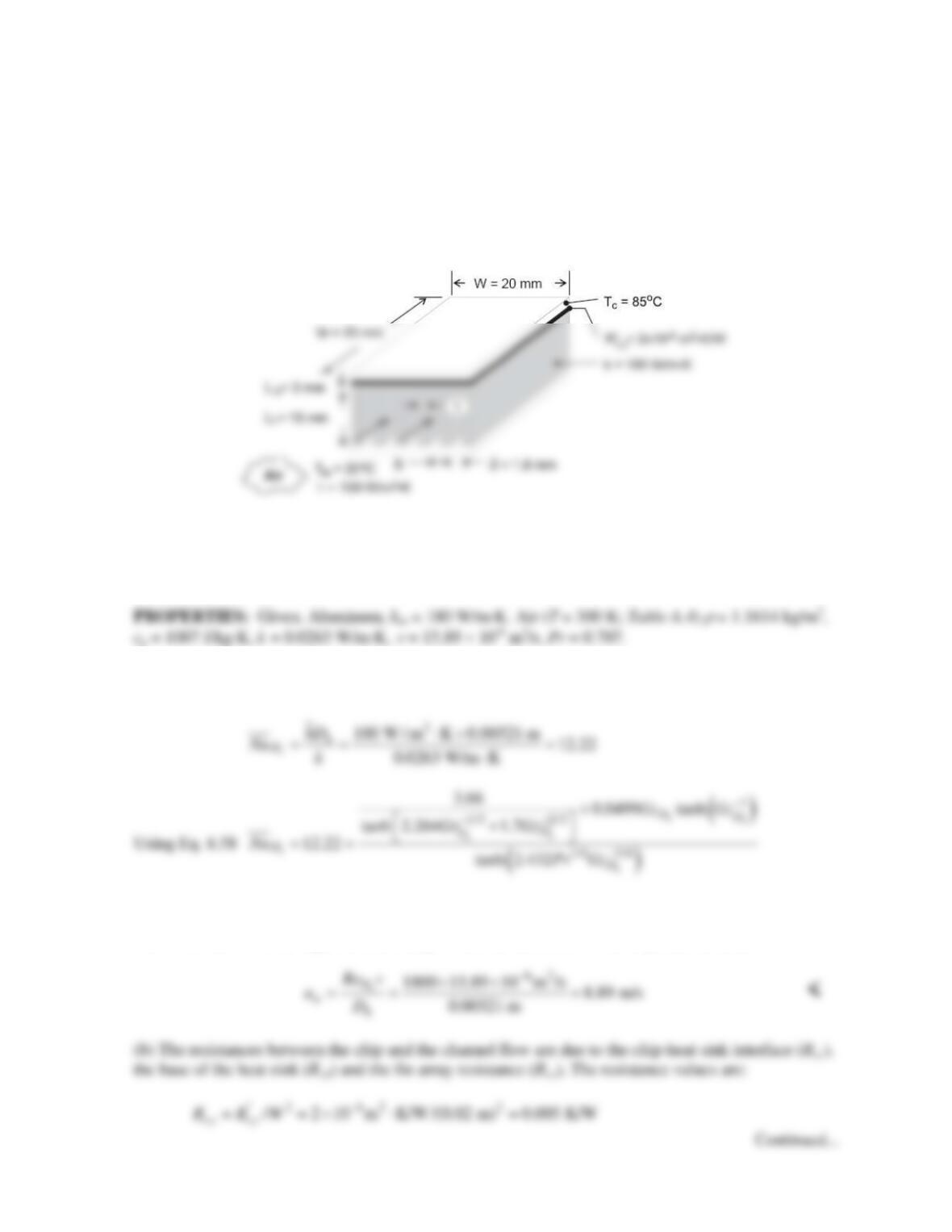
Therefore, the modified effectiveness is ε*=3545/5940 = 0.597, and the modified NTU is
The aluminum and steel temperature histories are shown below.
COMMENTS: (1) The value of the thermal contact resistance may change with time, modifying the
time needed to complete the process. (2) The Biot number for either the steel collar or aluminum pin
may be expressed as
eff c c t ,c
Bi h L/k L/(kR )
′′
= =
. Assuming kAA = 160 W/m∙K from inspection of
PROBLEM 11.68
KNOWN: Dimensions and maximum allowable temperature of an electronic chip. Thermal contact
resistance between chip and heat sink. Dimensions and thermal conductivity of heat sink. Inlet
temperature and convection coefficient associated with air flow through the heat sink.
FIND: (a) Inlet air velocity using an appropriate correlation from Chapter 8, (b) Chip power, qc and
the outlet temperature of the air exiting the channels. (c) Chip power and air outlet temperature for air
velocity half of the value calculated in part (a).
SCHEMATIC
ASSUMPTIONS: (1) Steady state, (2) One–dimensional heat transfer in fins and base, (3) Isothermal
chip, (4) Negligible heat transfer from top of chip, (5) Uniform convection coefficient over exposed
surfaces, (6) Negligible radiation, (7) Negligible axial conduction in the heat sink, (8) Laminar flow,
(9) Combined entry length.
ANALYSIS: (a) The hydraulic diameter is Dh = 4Ac/P = 4Lf (S – t)/[2(S – t) + 2Lf] = 4 × 0.0018 m ×
0.015 m/[2 × 0.0018 m + 2 × 0.015 m] = 0.00321 m. From the specified convection coefficient,
from which
204 ( / ) (0.00321/ 0.02) 0.707
hh h
D hD D
Gz D W Re Pr Re== = ××
. This yields
h
D
Re
=
1800. The flow is in the upper laminar range. From the definition of the Reynolds number,