PROBLEM 11.46
KNOWN: Engine oil cooled by air in a cross-flow heat exchanger with both fluids unmixed.
FIND: (a) Heat transfer coefficient on oil side of exchanger assuming fully-developed conditions and
constant wall heat flux, (b) Effectiveness, and (c) Outlet temperature of the oil.
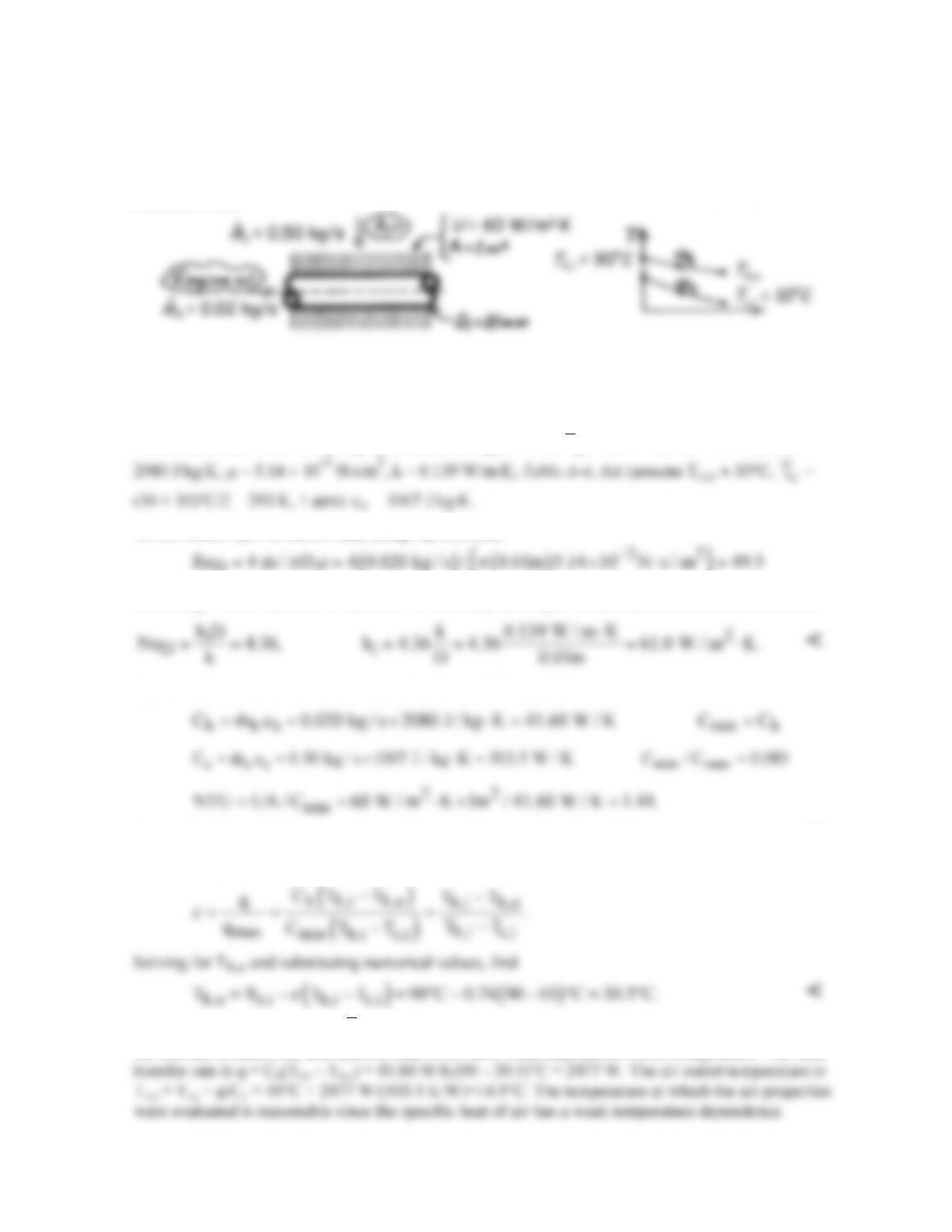
SCHEMATIC:
ASSUMPTIONS: (1) Negligible heat loss to surroundings, (2) Constant properties, (3) Oil flow and
thermal conditions are fully developed, (4) Oil cooling process approximates constant wall flux
conditions.
PROPERTIES: Table A-5, Engine oil (assume Th,o ≈ 45°C,
h
T
= (45 + 90)°C/2 = 341 K): ch =
ANALYSIS: (a) For the oil side, using Eq. 8.6, find,
()
D
Since ReD < 2000 the flow is laminar. For the fully-developed conditions with constant wall flux,
(b) The effectiveness can be determined by the ε-NTU method.
Using Fig. 11.14, with Cmin/Cmax = 0.083 and NTU = 1.44, find ε ≈ 0.74. <
(c) From Eqs. 11.19 and 11.18,
COMMENTS: Note that the
h
T
value at which the oil properties were evaluated is reasonable since
the thermal conductivity and specific heat of oil have weak dependence on oil temperature. The heat
PROBLEM 11.47
KNOWN: Shell–tube heat exchanger with one shell and single tube pass; Tube side: exhaust gas with
specified flow rate and temperature change; Shell side: supply of saturated water at 11.7 bar; Tube
dimensions and thermal conductivity, and fouling resistance on gas side,
′′
Rf,h,
specified.
FIND: Number of tubes and their length if the gas velocity is not to exceed um,i = 25 m/s.
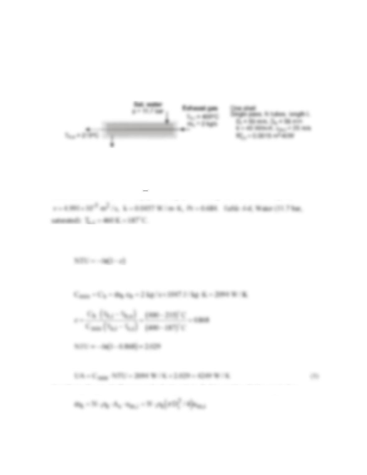
SCHEMATIC:
ASSUMPTIONS: (1) Steady-state conditions, (2) Negligible losses to the surroundings, (3)
Negligible water–side thermal resistance, (4) Exhaust gas properties are those of atmospheric air, (5)
Gas-side flow is fully developed, and (6) Constant properties.
PROPERTIES: Table A-4, Air
T K
h
=581
cT:
ρ
=0 600. , kg / m
3
c 1047 J / kg K,= ⋅
c,i= =460
ANALYSIS: We’ll employ the NTU–ε method to design the exchanger. Since Cr = 0, use Eq.
11.35b.
where the effectiveness can be evaluated from Eqs. 11.18 and 11.19.
From Eq. 11.24,
Considering the gas-side flow rate and velocity criteria, find the number of tubes required as
Continued …
PROBLEM 11.47 (Cont.)
The overall coefficient, considering the convection process, fouling resistance and the tube thermal
resistance, is evaluated as
where the gas–side convection coefficient estimate is explained in the Comments section. Substituting
numerical values, determine the required tube length
COMMENTS: (1) Is the assumption of negligible water-side thermal resistance reasonable?
Explain why.
(2) Knowing the tube gas-side velocity, the usual convection correlation calculation methodology is
PROBLEM 11.48
KNOWN: Hot and cold gas flow rates and inlet temperatures of a recuperator. Overall heat transfer
coefficient. Desired cold gas outlet temperature.
FIND: (a) Required surface area, (b) Effect of surface area on cold–gas outlet temperature.
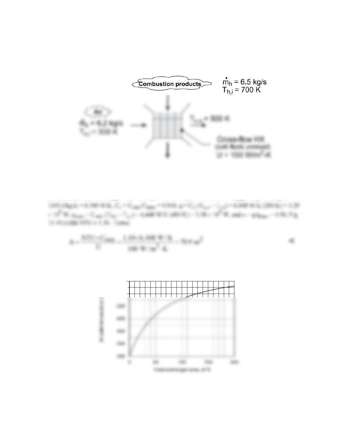
SCHEMATIC:
ASSUMPTIONS: (1) Negligible heat loss to surroundings, (2) Constant properties.
PROPERTIES: Given: cp,c = cp,h = 1040 W/m⋅K.
ANALYSIS: (a) With Cmin = Cc = 6.2 kg/s × 1040 J/kg⋅K = 6,448 W/K, Cmax = Ch = 6.5 kg/s ×
(b) Using the Heat Exchanger option of IHT, the following result was obtained
The air outlet temperature increases, of course, with increasing heat exchanger area, but the approach
to the maximum possible outlet temperature, Th,i, is slow and the heat exchanger size needed to
achieve a large outlet temperature may be prohibitively expensive.
550
600
PROBLEM 11.49
KNOWN: Inlet temperature and flow rates for a concentric tube heat exchanger. Hot fluid outlet
temperature.
FIND: (a) Maximum possible heat transfer rate and effectiveness, (b) Preferred mode of operation.
SCHEMATIC:
ASSUMPTIONS: (1) Steady-state operation, (2) Negligible heat loss to surroundings, (3) Fixed
overall heat transfer coefficient.
ANALYSIS: (a) Using the ε–NTU method, find
Hence from Eq. 11.19,
max
q / q 26,920 / 57,290 0.47.
ε
= = =
<
(b) From Eq. 11.7b,
Hence from Eq. 11.24
( ) ( ) ( ) ( )
CF PF CF PF
A / A NTU / NTU 0.75 / 0.95 0.79.= ≈=
Because of the reduced size requirement, and hence capital investment, the counterflow mode of
operation is preferred. <
PROBLEM 11.50
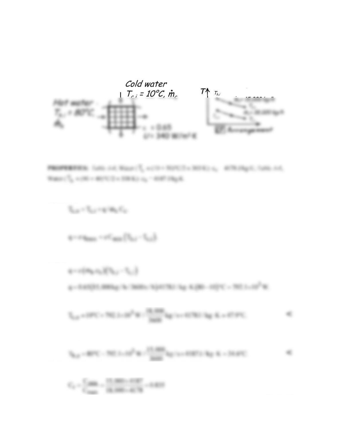
KNOWN: Single–pass, cross-flow heat exchanger with both fluids (water) unmixed; hot water enters
at 80°C and at 15,000 kg/h while cold water enters at 10°C and at 18,000 kg/h; effectiveness is 65%.
FIND: Cold water exit temperature, Tc,o.
SCHEMATIC:
ASSUMPTIONS: (1) Negligible heat loss to surroundings, (2) Constant properties.
ANALYSIS: From an energy balance on the cold fluid, Eq. 11.7b, the outlet temperature can be
expressed as
The heat rate can be written in terms of the effectiveness and qmax. Using Eqs. 11.19 and 11.18,
By inspection, it can be noted that the hot fluid is the minimum capacity fluid. Substituting numerical
values,
The exit temperature of the cold water is then
The exit temperature of the hot water is
The heat transfer surface area is found by determining the NTU.
Continued…
PROBLEM 11.50 (Cont.)
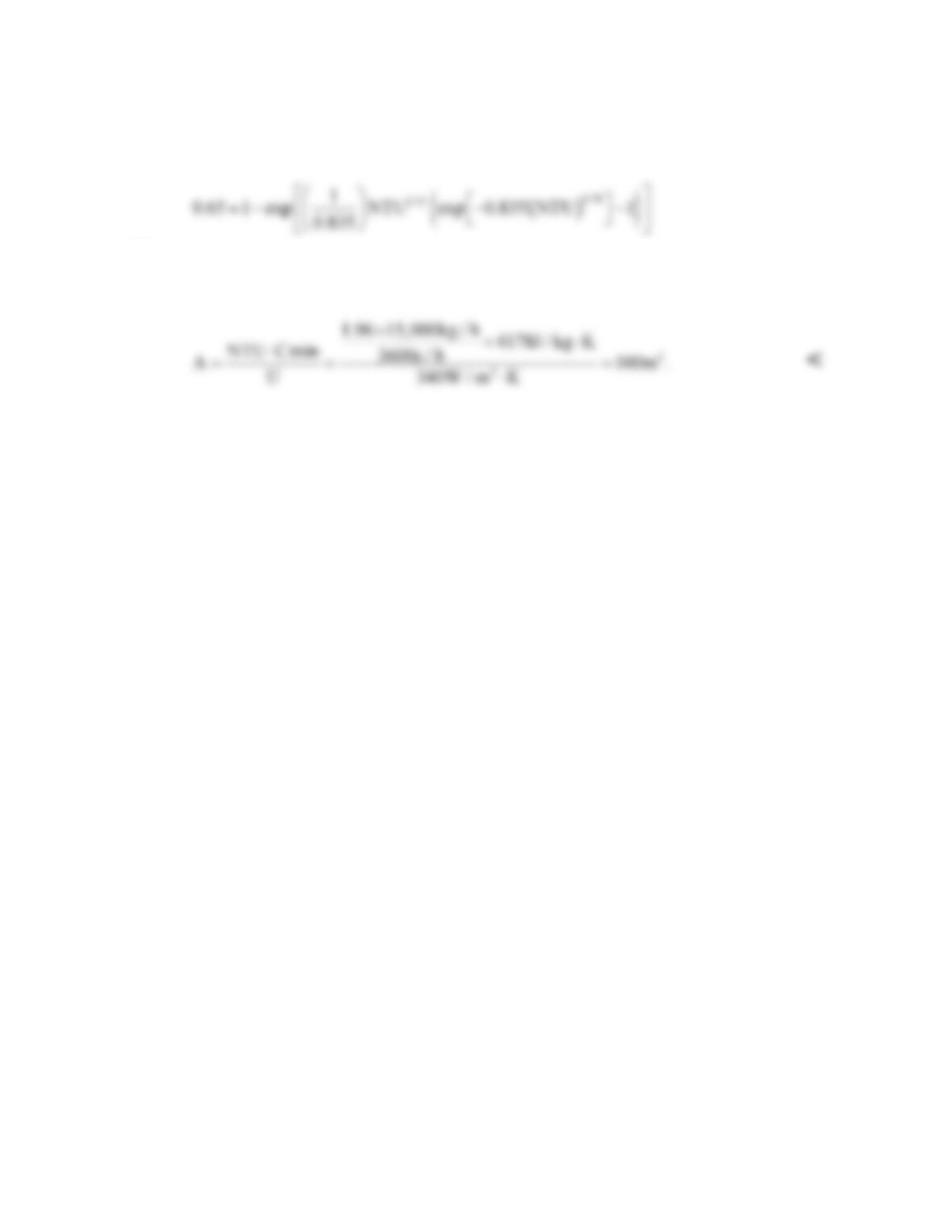
and from Eq. 11.32 (solved iteratively, or with IHT)
or
NTU = 1.96. From the definition of NTU,
COMMENTS: The outlet temperatures that were assumed for purposes of property evaluation (Tc,o ≈
50°C and Th,o ≈ 40°C) are sufficiently close to the actual values since cp varies little over this
temperature range.
PROBLEM 11.51
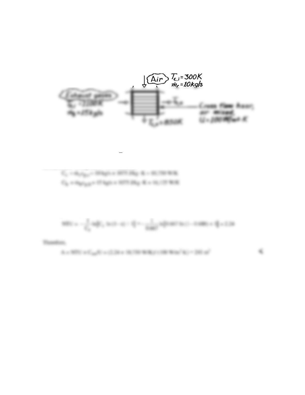
KNOWN: Flow rates and inlet temperatures of exhaust gases and combustion air used in a cross–
flow (one fluid mixed) heat exchanger. Overall heat transfer coefficient. Desired air outlet
temperature.
FIND: Required heat exchanger surface area.
SCHEMATIC:
ASSUMPTIONS: (1) Steady-state conditions, (2) Negligible heat loss to surroundings, (3) Constant
properties, (4) Gas properties are those of air.
PROPERTIES: Table A-4, Air (
m
T
≈ 700 K, 1 atm): cp = 1075 J/kg⋅K.
ANALYSIS: Using the ε – NTU method,
Thus
r min max max c,o c,i h,i c,i
C = C /C = 0.667, ε = q/q = (T T )/(T T ) = 0.688−−
From Eq. 11.34b,
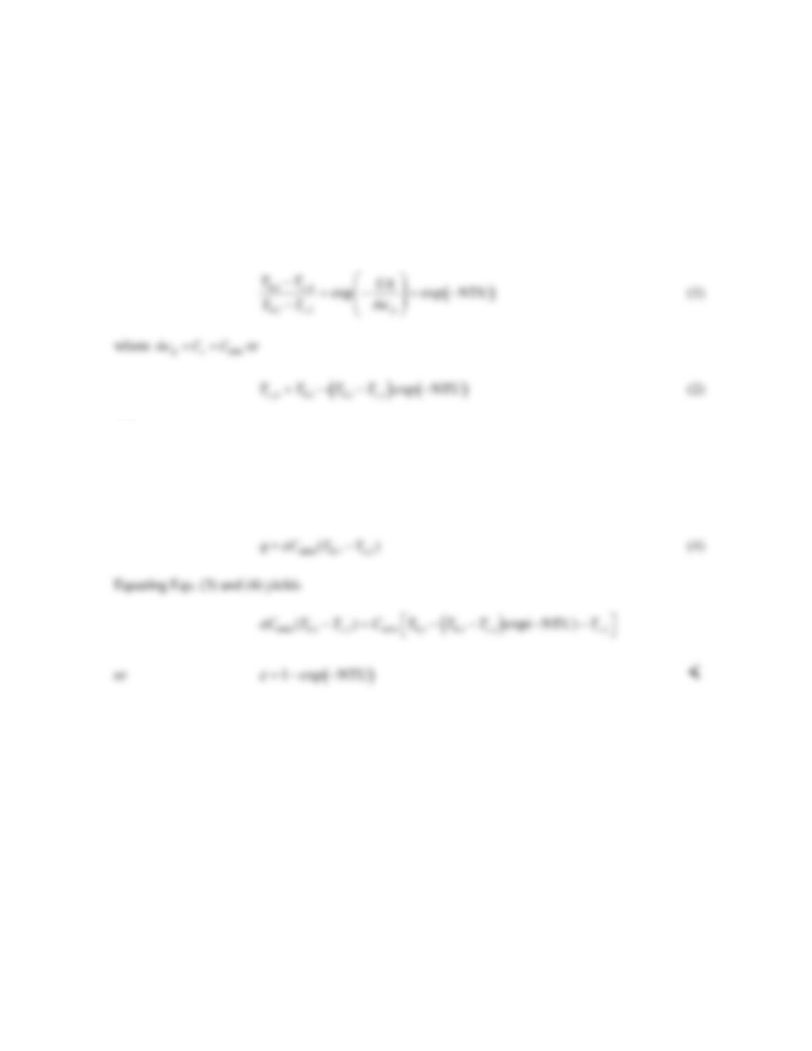
PROBLEM 11.52
KNOWN: Heat exchanger with Cr = 0.
FIND: Derivation of Equation 11.35a.
ASSUMPTIONS: (1) Negligible heat transfer between heat exchangers and surroundings, negligible
heat transfer between two heat exchangers, (2) Constant properties.
ANALYSIS: For Cr = 0, Cmax → ∞. If the hot stream is associated with Cmax, then Th,i = Th,o. From
Eq. 8.45 with T∞ = Th,i and Tm,o = Tc,o, Tm,i = Tc,i,
and
( ) ( ) ( )
, , min , , min , , , ,
exp( NTU)
p mo mi co ci hi hi ci ci
q mc T T C T T C T T T T
= − = −= −− − −
(3)
From Eq. 11.22,
COMMENTS: Eq. 11.35a may be used to solve a wide variety of problems, beyond those
associated with two–fluid heat exchangers, involving constant surface temperature conditions.
PROBLEM 11.53
KNOWN: Inlet and outlet temperatures of natural gas and seawater in an LNG vaporizer. LNG flow
rate and properties of its liquid and vapor phases, as well as phase change temperature and latent heat
of vaporization. Overall heat transfer coefficients for three sections of the vaporizer. Seawater
properties.
FIND: Required vaporizer heat transfer area.
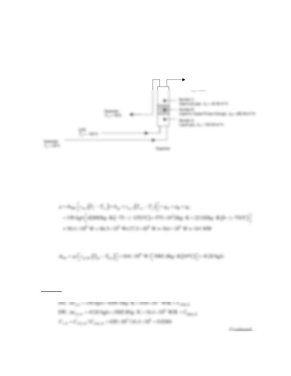
SCHEMATIC:
ASSUMPTIONS: (1) Negligible heat transfer between the heat exchanger and the surroundings, (2)
Constant properties, (3) Parallel flow.
PROPERTIES: Given. NG: cp,l = 4200 J/kg⋅K, cp,v = 2210 J/kg⋅K, hfg = 575 kJ/kg, Tf = -75°C. SW:
cp,SW = 3985 J/kg⋅K.
ANALYSIS: Application of the conservation of energy principle to the gas stream yields
The flow rate of seawater is
Recognizing that the outlet conditions of Section A (B) serve as inlet conditions to Section B (C), we
may analyze the vaporizer on a section-by-section basis.
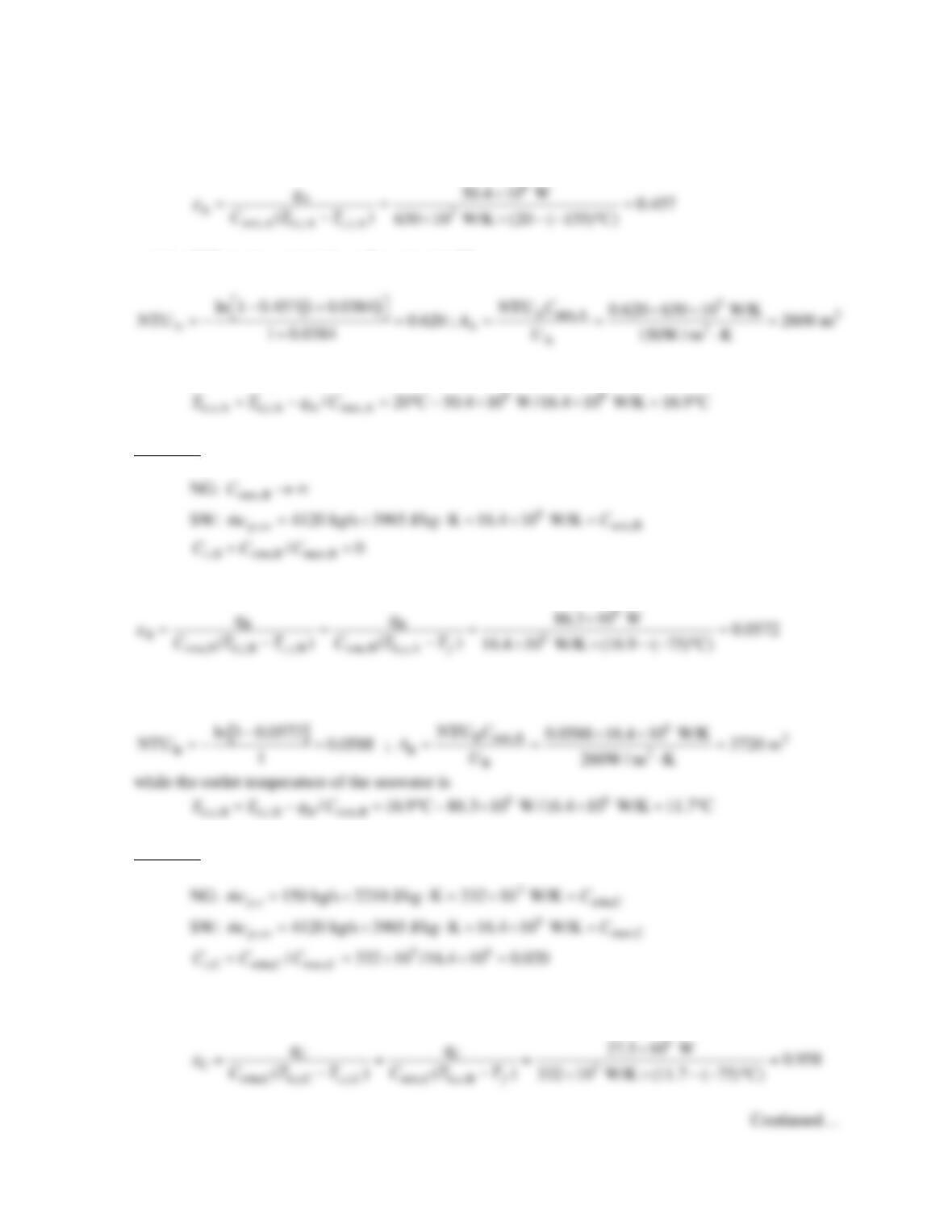
Section A The heat capacity rates are
Vaporized gas
to pipeline
PROBLEM 11.53 (Cont.)
The effectiveness is
and the NTU is determined from Equation 11.28b
while the outlet temperature of the seawater is
Section B The heat capacity rates are
The effectiveness is
and the NTU is determined from Equation 11.28b
Section C The heat capacity rates are
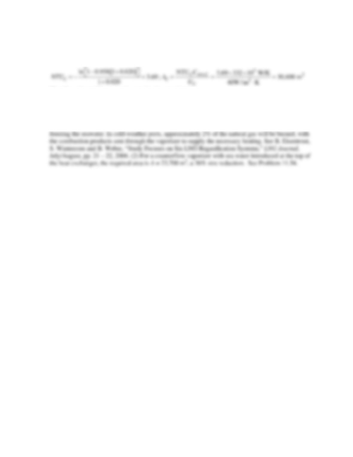
The effectiveness is
PROBLEM 11.53 (Cont.)
and the NTU is found from Equation 11.28b
Therefore, the total heat transfer area for the vaporizer is
2222
ABC
2600 m +3720 m + 30,600 m = 36,900 mAA A A=++= <
COMMENTS: (1) The scheme may not be feasible in a cold-weather port due to the potential of
PROBLEM 11.54
KNOWN: Inlet and outlet temperatures of natural gas and seawater in an LNG vaporizer. LNG flow
rate and properties of its liquid and vapor phases, as well as phase change temperature and latent heat
of vaporization. Overall heat transfer coefficients for three sections of the vaporizer. Seawater
properties.
FIND: Required vaporizer heat transfer area.
SCHEMATIC:
ASSUMPTIONS: (1) Negligible heat transfer between the heat exchanger and the surroundings, (2)
Constant properties, (3) Counterflowing fluids.
ANALYSIS: Application of the conservation of energy principle to the gas stream yields
The flow rate of seawater is
Recognizing that the NG (cold stream) outlet conditions of Section A (B) serve as NG inlet conditions
to Section B (C), and that the SW (hot stream) outlet conditions of Section C (B) serve as the SW inlet
conditions for Section B(A), we may write
Section A The heat capacity rates are
Vaporized gas
to pipeline
PROBLEM 11.54 (Cont.)
The effectiveness is
The NTU is determined from Equation 11.29b
and the area of Section A is
Section B The heat capacity rates are
NG: max,B
C→∞
SW: 6
,sw min,B
4120 kg/s 3985 J/kg K 16.4 10 W/K
p
mc C=×⋅=×=
,A min,B max,B
/0
r
CC C==
The effectiveness is
Section C The heat capacity rates are
The effectiveness is
and the NTU is found from Equation 11.29b
Continued…
PROBLEM 11.54 (Cont.)
Therefore, the total heat transfer area for the vaporizer is
COMMENTS: (1) The scheme may not be feasible in a cold-weather port due to the potential of
freezing the seawater. In cold-weather ports, approximately 2% of the natural gas will be burned, with
the combustion products sent through the vaporizer to supply the necessary heating. See B. Eisentrout,
PROBLEM 11.55
KNOWN: Inlet and outlet temperatures and flow rates for a shell-and-tube heat exchanger with
a single shell and 100 tubes making two passes. Tube inner and outer diameters and length. Heat
transfer coefficient for ethylene–glycol water mixture flowing in shell.
FIND: (a) Heat transfer rate and outlet temperatures when the tubes are copper. (b) For nylon
tubes, heat exchanger length required to transfer the same amount of energy as in part (a).
SCHEMATIC:
ASSUMPTIONS: (1) Negligible heat loss to the surroundings, (2) Constant properties, (3)
Fully developed water flow in tubes.
PROPERTIES: Table A.6, water (T ≈ 300 K): k = 0.613 W/m⋅K, cp = 4179 J/kg⋅K, m = 855 ×
ANALYSIS: (a) We begin by finding the heat transfer coefficient for the flow in tubes. The
Reynolds number is
Hence the flow is turbulent and we can use the Dittus-Boelter correlation,
4 / 5 0.4 4 4 / 5 0.4
ci D
42
h (k / D )0.023Re Pr (0.613 W / m K / 0.0036 m)0.023(1.03 10 ) (5.83)
1.29 10 W / m K
= =⋅×
=×⋅
Ethylene–glycol
PROBLEM 11.55 (Cont.)
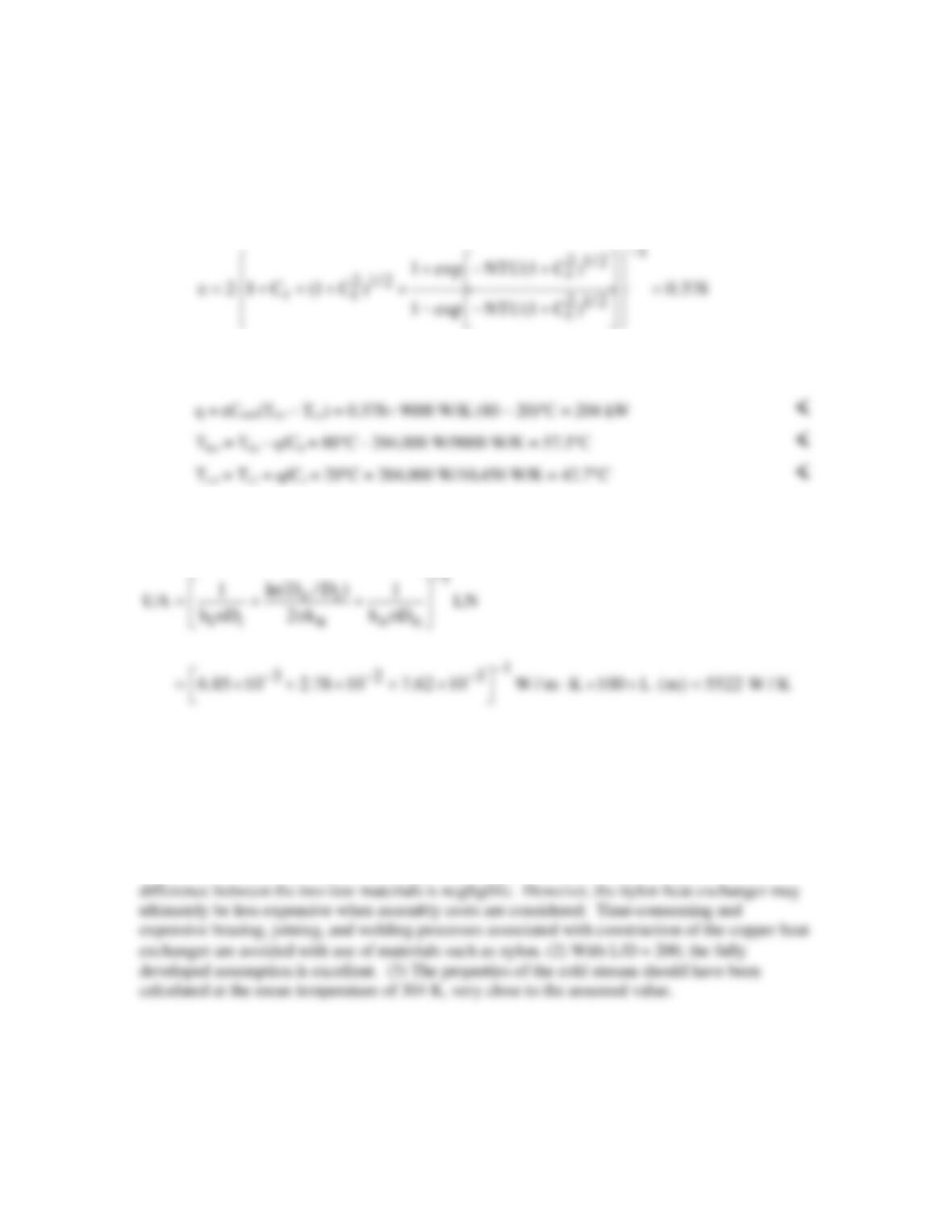
Using the ε–NTU method, Cmin = Ch = 2.5 kg/s × 3600 J/kg⋅K = 9000 W/K, Cmax = 2.5 kg/s ×
4179 J/kg⋅K = 10,450 W/K, Cr = 0.861, and NTU = UA/Cmin = 0.614. Then from Eq. 11.30a,
and from Eqs. 11.18, 11.19, 11.6b, and 11.7b,
(b) In order to maintain the same heat rate, we must have the same effectiveness, which means
that NTU and UA must be the same as in part (a). When the tubes are nylon, we can recalculate
UA from Eq. (1),
Solving for L,
L = 2.33 m <
COMMENTS: (1) The nylon tube bundle is significantly larger due to nylon’s low thermal
conductivity relative to the copper. Based upon a nylon density of 1150 kg/m3, the masses of the
two tube bundles are 0.83 kg and 0.39 kg for the copper and nylon, respectively. The cost
PROBLEM 11.56
KNOWN: Heat exchanger operating in parallel-flow configuration.
FIND: Expression for Rlm/Rt which doesn’t involve temperatures. Plot result.
SCHEMATIC:
ASSUMPTIONS: (1) Negligible heat loss to surroundings, (2) Negligible change in kinetic and
potential energy.
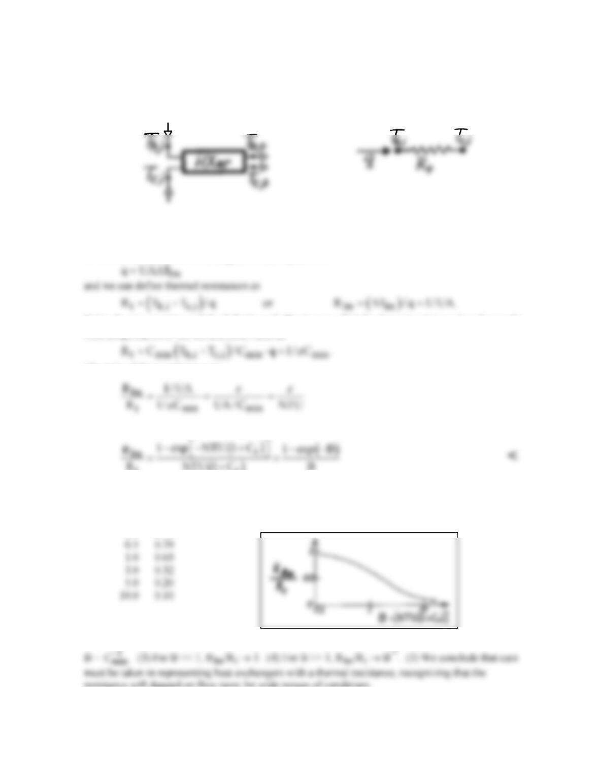
ANALYSIS: (a) For the exchanger, the rate equation is
Using the rate equation and the definition of effectiveness, find the thermal resistance based upon the
inlet temperatures of the hot and cold fluids as
The ratio of these resistances is
and for the parallel flow, concentric tube configuration using Eq. 11.28a,
( )
tr
R NTU 1 C B
+
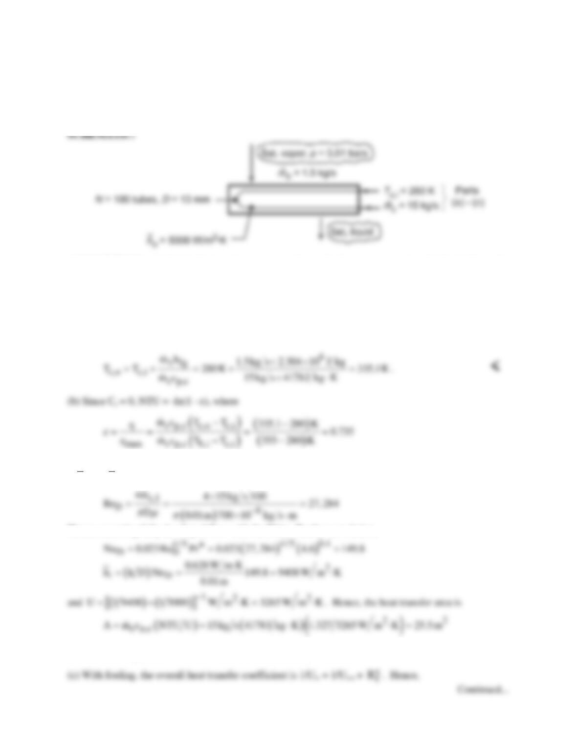
where B = NTU(1 + Cr). Evaluating the ratio for various values of B, find
B Rlm/Rt <
0.1 0.95
COMMENTS: (1) For Cmax → ∞, Cr → 0; hence B → NTU. (2) For Cmax ≈ Cmin , B → 2NTU or
resistance will depend on flow rates for wide ranges of conditions.
PROBLEM 11.57
KNOWN: Flow rate and pressure of saturated vapor entering a condenser. Number and diameter of
condenser tubes. Water flow rate and inlet temperature. Tube outside convection coefficient.
FIND: (a) Water outlet temperature, (b) Total tube length, (c) Effect of fouling on mass condensation,
(d) Effect of water flow rate and inlet temperature on condenser performance.
ASSUMPTIONS: (1) Negligible heat loss to surroundings, (2) Constant properties, (3) Negligible wall
conduction resistance and fouling (initially).
PROPERTIES: Water (given): cp = 4178 J/kg⋅K, m = 700 × 10–6 kg/s⋅m, k = 0.628 W/m⋅K, Pr = 4.6;
Table A.6, Sat. steam (355 K): hfg = 2.304 × 10⁶ J/kg; With fouling:
f
R′′
= 0.0003 m2⋅K/W.
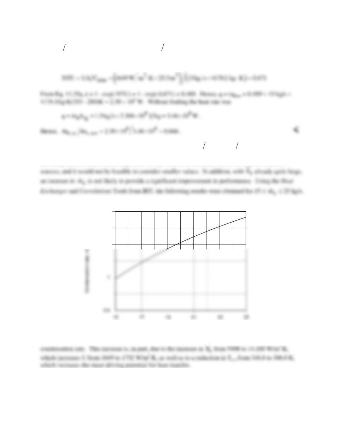
ANALYSIS: (a) From an energy balance, qh =
( ) ( )
h h,i h,o h fg c c p,c c,o c,i
m i i m h q mc T T−= == −
, or
Hence, NTU = -ln(1 – 0.735) = 1.327 = UA/Cmin. The overall heat transfer coefficient is given by 1/U =
1/
i
h
+ 1/
o
h
. For the internal tube flow,
Hence, assuming fully developed flow with the Dittus-Boelter correlation,
and the tube length is L = A/NπD = 25.5 m2/100π(0.01 m) = 8.11 m. <
PROBLEM 11.57 (Cont.)
()
4 42
w
1 U 3.063 10 3 10 m K W
−−
= × +× ⋅
Uw = 1649 W/m2⋅K.
The condensation rate with fouling is then
h,w
m 0.666 1.5 kg s 0.998 kg s=×=
.
(d) The prescribed water inlet temperature of Tc,i = 280 K is already at the lower limit of available
c
m
Water mass flow rate, mdotc(kg/s)
1.1
1.2
Over the specified range of
c
m
, there is approximately an 18% increase in the heat rate, and hence in the
COMMENTS: There is a significant reduction in performance due to fouling, which can not be restored
by increasing
c
m
. The desired performance could be achieved by oversizing the condenser, that is, by
increasing the number of tubes and/or the tube length.