PROBLEM 11.33 (Cont.)
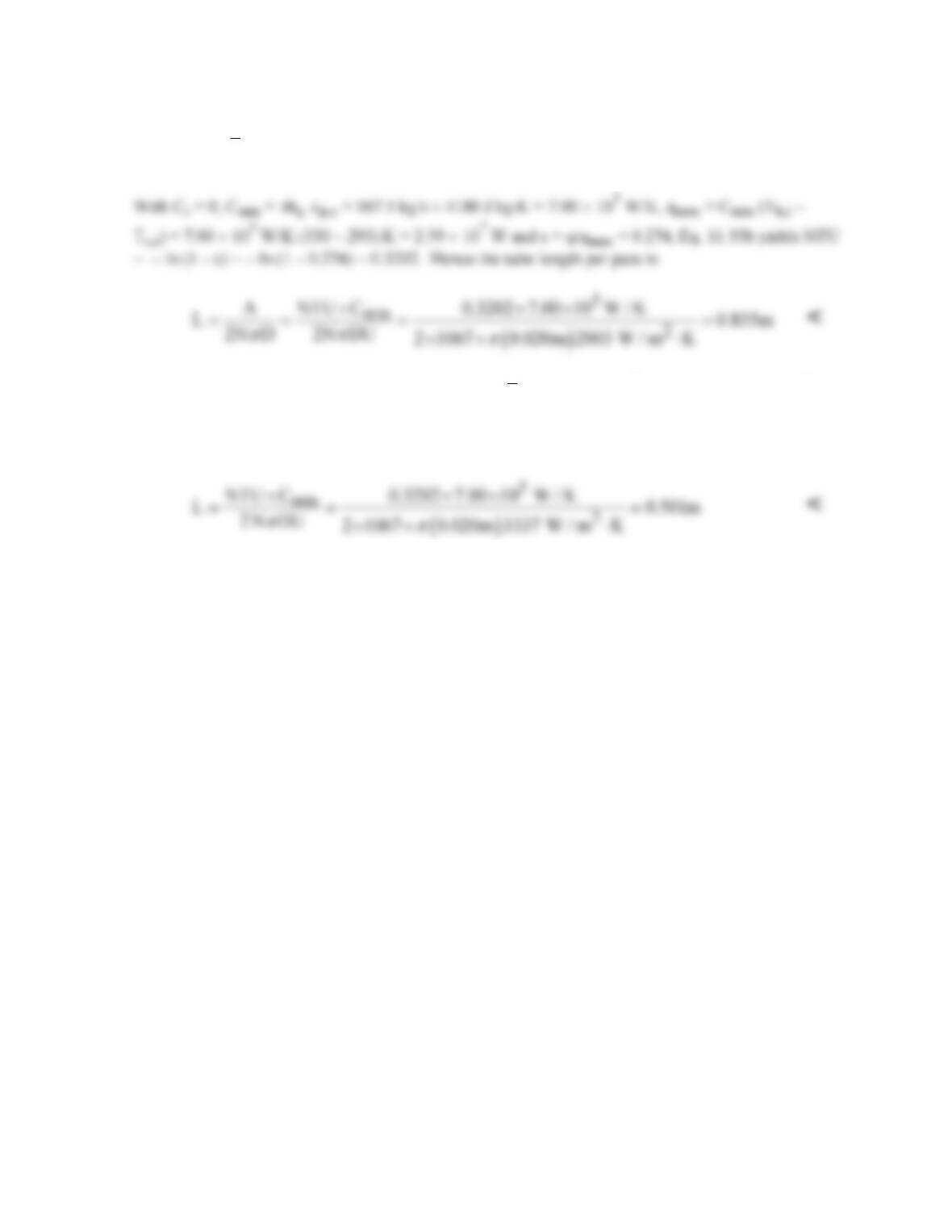
Hence,
1
11 2
o
i
U h h 2003 W / m K
−
−−
=+= ⋅
(b) If the tube-side convection coefficient is doubled,
2
i
h 5008 W / m K= ⋅
and U = 3337 W/m2⋅K.
Since q, Cr, Cmin, qmax and hence ε are unchanged, the number of transfer units is still NTU =
0.3202. Hence, the tube length per pass is now
COMMENTS: Heat transfer enhancement for the internal forced convection flow significantly
reduces the size of the heat exchanger.
PROBLEM 11.34
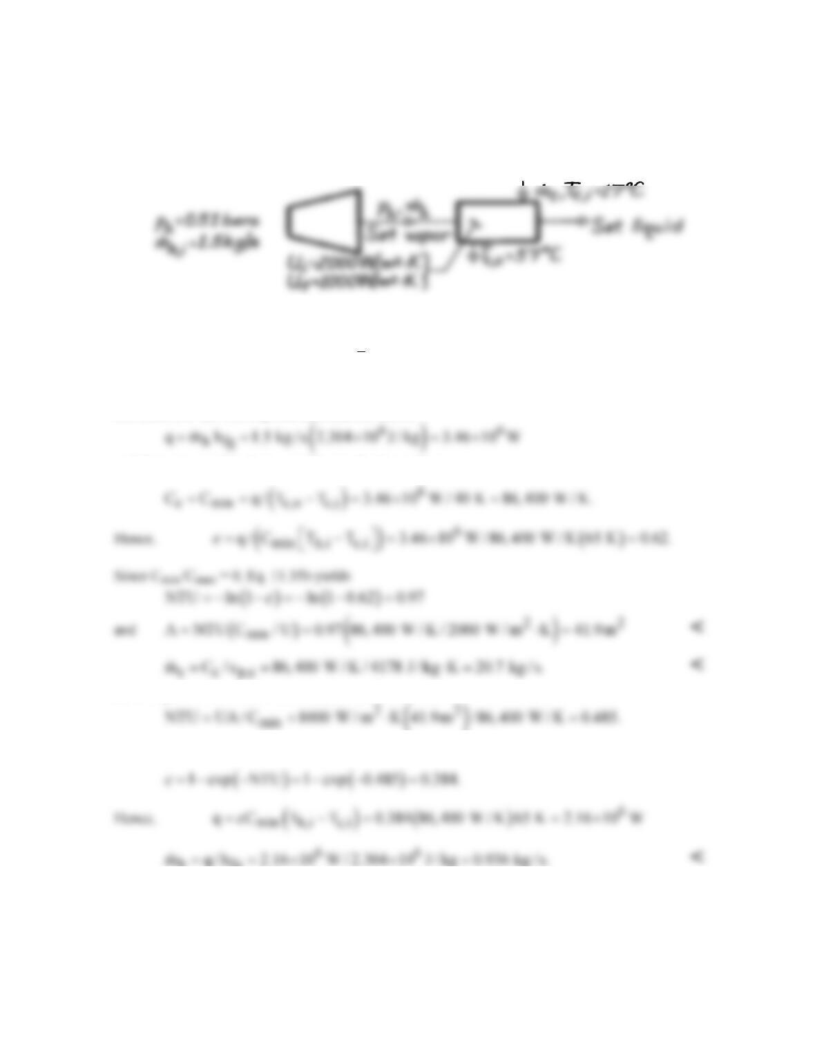
KNOWN: Pressure and initial flow rate of water vapor. Water inlet and outlet temperatures. Initial
and final overall heat transfer coefficients.
FIND: (a) Surface area for initial U and water flow rate, (b) Vapor flow rate for final U.
SCHEMATIC:
ASSUMPTIONS: (1) Negligible heat loss to surroundings, (2) Negligible wall conduction
resistance.
PROPERTIES: Table A-6, Sat. water (
c
T
= 310 K): cp,c = 4178 J/kg⋅K; (p = 0.51 bars): Tsat = 355
K, hfg = 2304 kJ/kg.
ANALYSIS: (a) The required heat transfer rate is
and the corresponding heat capacity rate for the water is
(b) Using the final overall heat transfer coefficient, find
Since Cmin/Cmax = 0, Eq. 11.35a yields
h fg
COMMENTS: The significant reduction (38%) in
h
m
represents a significant loss in turbine power.
Periodic cleaning of condenser surfaces should be employed to minimize the adverse effects of
fouling.
PROBLEM 11.35
KNOWN: Two-fluid heat exchanger with prescribed inlet and outlet temperatures of the two fluids.
FIND: (a) Whether exchanger is operating in parallel or counter flow, (b) Effectiveness of the
exchanger when Cc = Cmin.
SCHEMATIC:
ASSUMPTIONS: (1) Negligible heat loss to the surroundings.
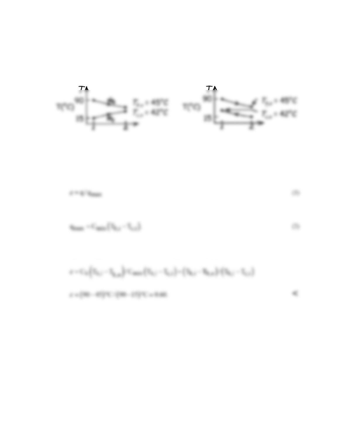
ANALYSIS: (a) To determine whether operation is PF or CF, consider the temperature distributions.
From the distributions we note that PF or CF operation is possible.
(b) The effectiveness of the exchanger follows from Eq. 11.19,
where from Eq. 11.18,
Since the hot fluid undergoes a larger temperature change than the cold fluid, Cmin = Ch and
performing an energy balance on the cold fluid, Eq. (1) with Eq. (2) becomes
COMMENTS: If Tc,o were greater than Th,o, parallel-flow operation would not be possible.
PROBLEM 11.36
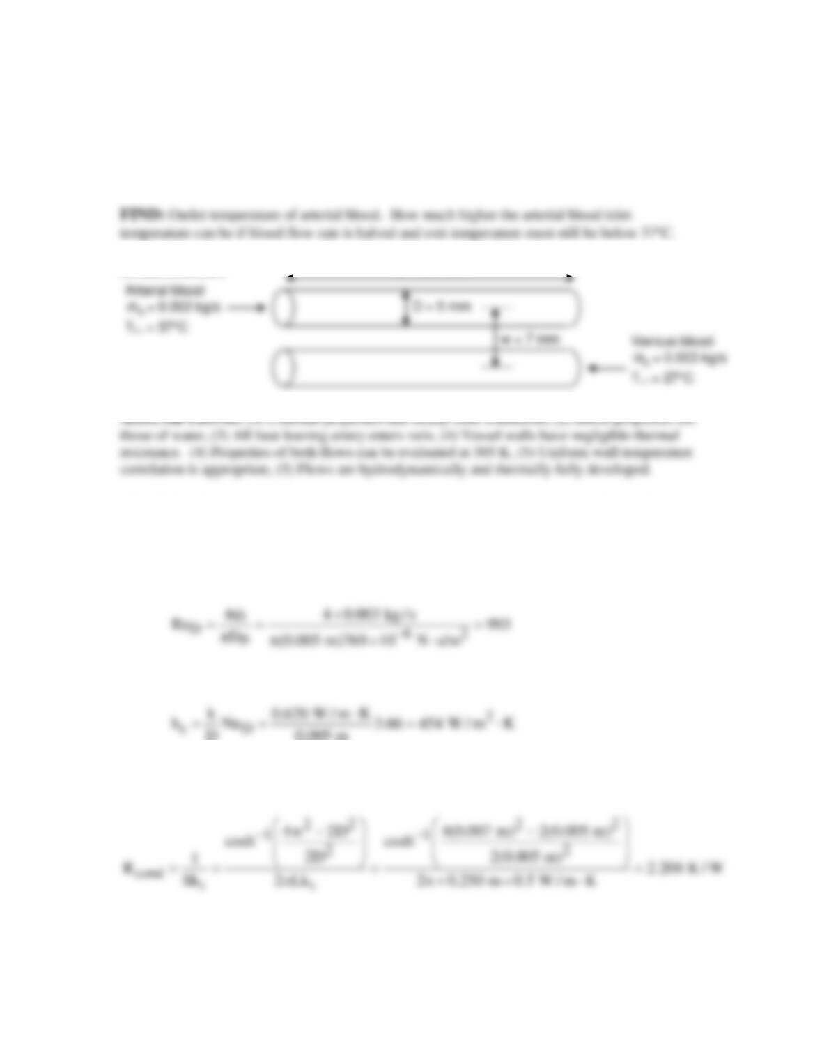
KNOWN: Length and diameters of vein and artery running from chest to base of skull.
Separation distance. Inlet temperatures and mass flow rates of blood flowing in opposite
directions in vein and artery. Thermal conductivity of surrounding tissue.
SCHEMATIC:
w = 7 mm
PROPERTIES: Table A.6, water: (T = 305 K): cp = 4178 J/kg⋅K, µ = 769 × 10-6 N⋅s/m2, k =
0.620 W/m⋅K,. Tissue (given): kt = 0.5 W/m⋅K.
ANALYSIS: The pair of vessels can be seen as a counterflow heat exchanger. We begin by
evaluating the heat transfer coefficients, which will be the same in both vessels. From Eq. 8.6,
Hence the flow is laminar and NuD = 3.66. Therefore,
D 0.005 m
With the assumption that all the heat that leaves the artery enters the vein, conduction between
the two cylinders can be represented by the shape factor in Table 4.1, case 4. Then
Then we can find UA for heat transfer between the two blood flows.
Continued…
L = 250 mm
PROBLEM 11.36 (Cont.)
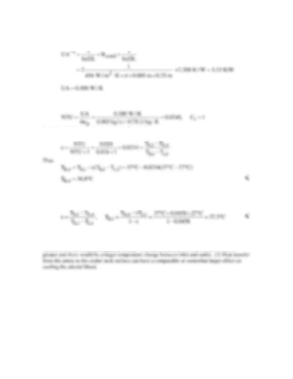
Now using the ε–NTU method, with equal heat capacity rates for the two flows,
From Eq. 11.29a, with Cr = 1 and using Eq. 11.20
If the mass flow rate is halved, the flows remain laminar and the heat transfer coefficients are
unchanged, as is UA. Thus, NTU doubles, i.e. NTU = 0.0480, and ε = 0.048/1.048 = 0.0458.
Thus
COMMENTS: (1) The assumed mean temperature is not accurate, but this is not worth
correcting since the properties of blood are not those of water. (2) With xfd,h = 0.05ReDPrD = 1.3
m, the flow is not fully developed thermally. The actual heat transfer coefficients would be
PROBLEM 11.37
KNOWN: A very long, concentric tube heat exchanger having hot and cold water inlet temperatures,
85°C and 15°C, respectively; flow rate of hot water is twice that of the cold water.
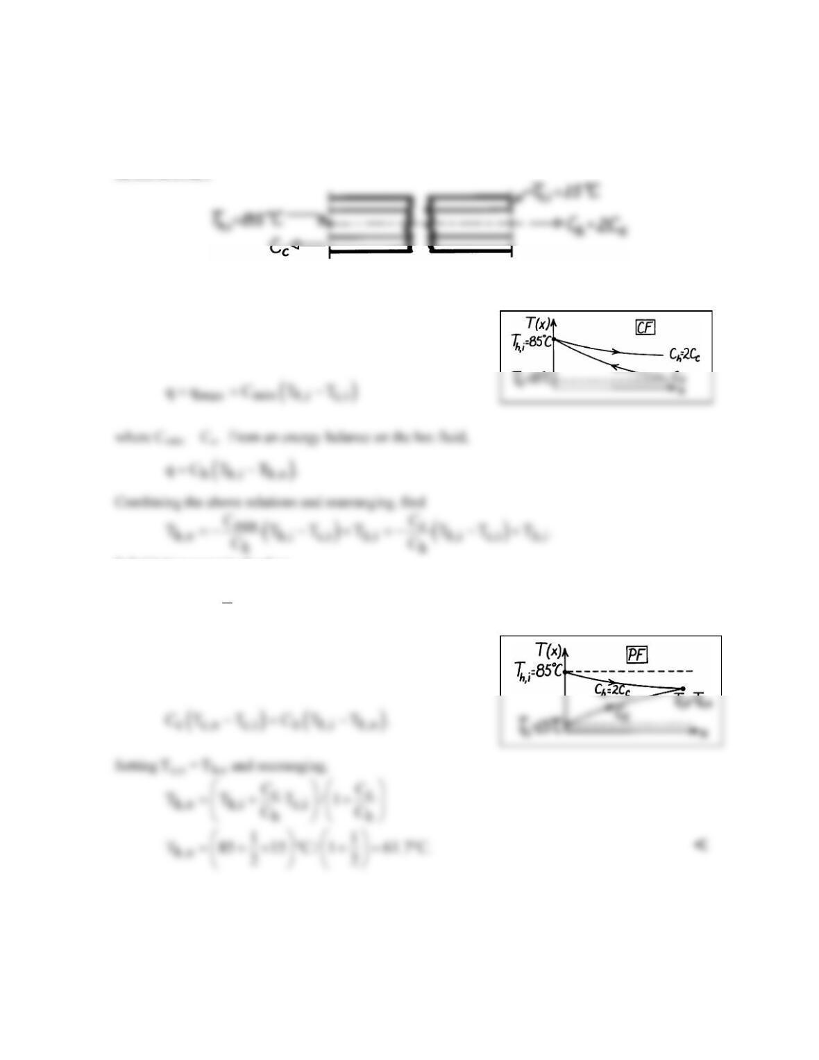
FIND: Outlet temperatures for counterflow and parallel flow operation.
SCHEMATIC:
ASSUMPTIONS: (1) Equivalent hot and cold water specific heats, (2) No heat loss to surroundings.
ANALYSIS: The heat rate for a concentric tube heat
exchanger with very large surface area operating in the
counterflow mode is
Substituting numerical values,
( )
h,o
1
T 85 15 C 85 C 50 C.
2
=− − °+ °= °
<
For parallel flow operation, the hot and cold outlet
temperatures will be equal; that is, Tc,o = Th,o.
Hence,
COMMENTS: Note that while ε = 1 for CF operation, for PF operation find ε = q/qmax = 0.67.
PROBLEM 11.38
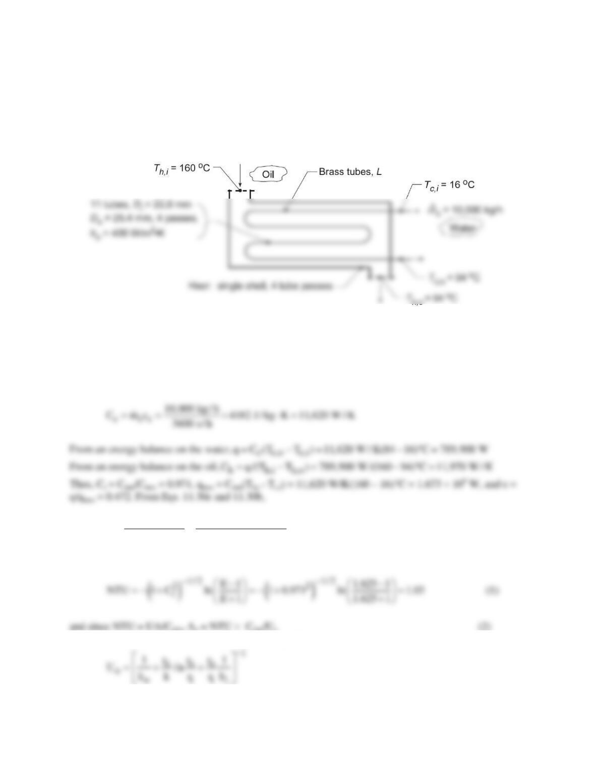
KNOWN: Conditions of oil and water for heat exchanger, one shell with 4 tube passes.
FIND: Length of exchanger tubes per pass, L; and (b) Compute and plot the effectiveness, ε, fluid
outlet temperatures, Th,o and Tc,o, and water-side convection coefficient, hc , as a function of the water
flow rate for 5000 ≤
c
m
≤ 15,000 kg / h for the tube length found in part (a) with all other conditions
remaining the same.
SCHEMATIC:
ASSUMPTIONS: (1) Negligible heat loss to surroundings, (2) Constant properties, (3) Fully–developed
flow in tubes.
PROPERTIES: Table A-1, Brass (400 K): k = 137 W/m⋅K; Table A-5, Water (323 K):
ρ
= 998.1
kg/m3, k = 0.643 W/m⋅K, cp = 4182 J/kg⋅K, m = 548 × 10-6 N⋅s/m2, Pr = 3.56.
ANALYSIS: (a) Using the ε–NTU method,
( ) ( )
r
1/2 1/2
22
r
2 / (1 C ) 2 / 0.472 (1 0.971)
E 1.625
1 C 1 0.971
ε−+ −+
= = =
++
Thus we can determine L if we know Uo. From Eq. 11.5,
where hi must be estimated from the appropriate correlation. With N = 11, the number of tubes,
Continued…
PROBLEM 11.38 (Cont.)
For fully developed turbulent flow, the Dittus-Boelter correlation with n = 0.4 yields
Returning now to Eq. (2), find Ao, then the length,
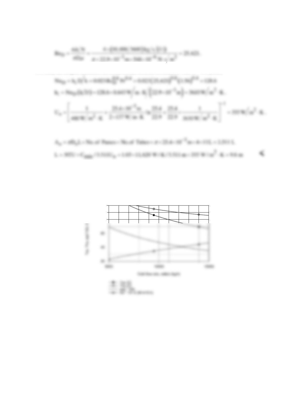
(b) Using the IHT Heat Exchanger Tool, Shell and Tube, One-shell pass and N tube passes, the
Correlation Tool, Forced Convection, Internal Flow for Turbulent, fully developed condition, and the
Properties Tool for Water, a model was developed using the effectiveness – NTU method to compute and
plot Tc,o , Th,o , ε, and hi as a function of
c
m
.
80
100
In order to avoid a boiling condition in the cold fluid, the cold flow rate should not be less than 8000
kg/h. As expected, Tc,o and Th,o decrease and the internal convection coefficient increases nearly linearly
with increasing flow rate. The effectiveness increases with increasing flow rate since the overall
convection coefficient is increasing.
COMMENT: The thermal resistance of the brass tubes is negligible. Since L/Di = 400, fully-developed
conditions are reasonable.
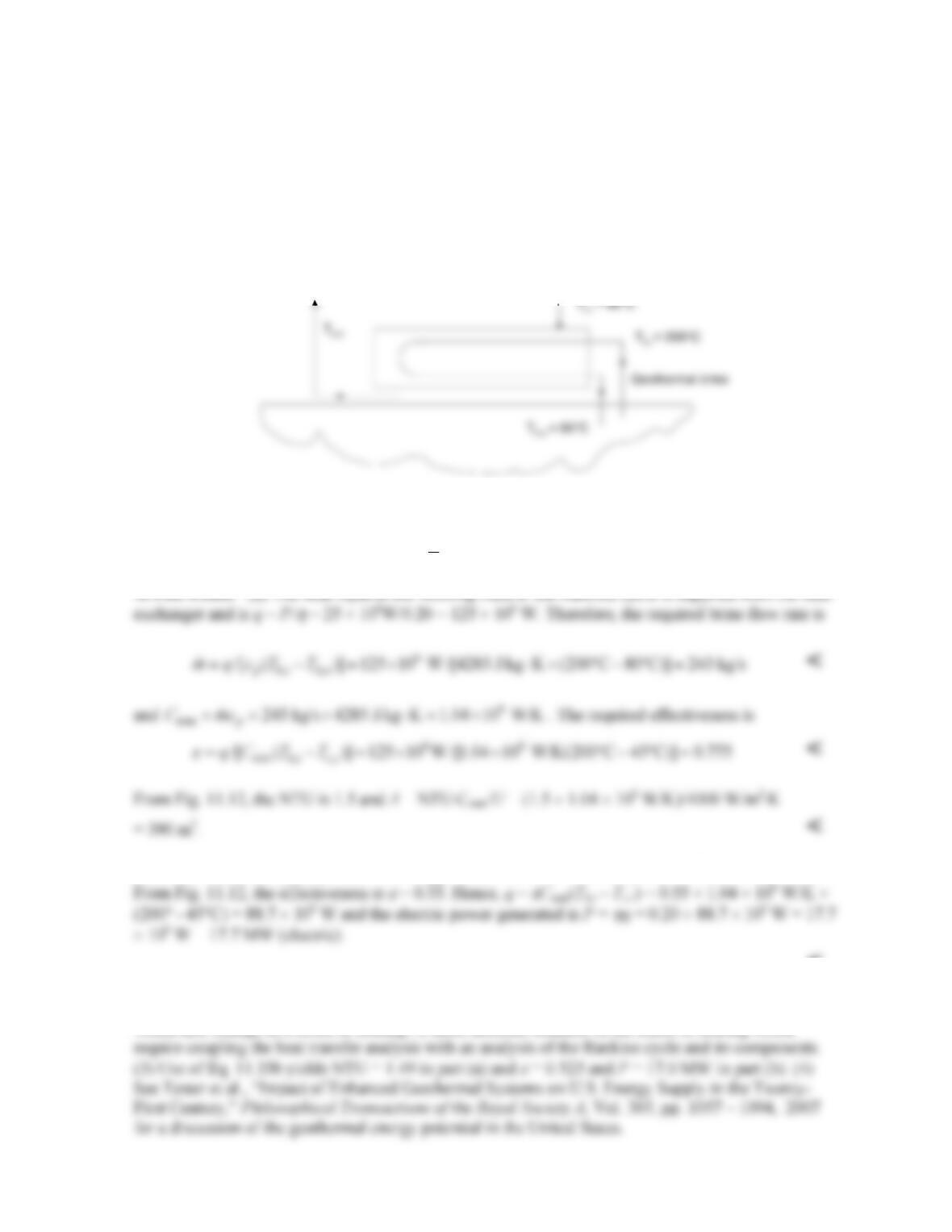
PROBLEM 11.39
KNOWN: Inlet temperatures of brine and working fluid in a geothermal power plant heat exchanger.
Brine outlet temperature. Electric power generation and thermal efficiency of the geothermal plant.
Overall heat transfer coefficients under clean and fouled conditions.
FIND: (a) Brine flow rate, heat exchanger effectiveness, required heat transfer surface area for clean
conditions. (b) Electric power generated under fouled conditions.
SCHEMATIC:
ASSUMPTIONS: (1) Negligible heat transfer between heat exchanger and surroundings, (2)
Constant properties.
PROPERTIES: Table A.6 brine (water),
T
= 140°C: cp = 4285 J/kg⋅K.
(b) Under fouled conditions, NTU = UA/Cmin = 2000 W/m2⋅K × 390 m2/(1.04 × 106 W/m2⋅K) = 0.75.
<
COMMENTS: (1) With this analysis, the electric power output is reduced by [(25 – 17.7)/25] × 100
= 29% due to fouling. (2) The outlet brine temperature as well as the inlet Rankine fluid temperature
would also change as a result of fouling. A more accurate estimate of the effect of fouling would
To Rankine cycle From Rankine cycle
η=0.20
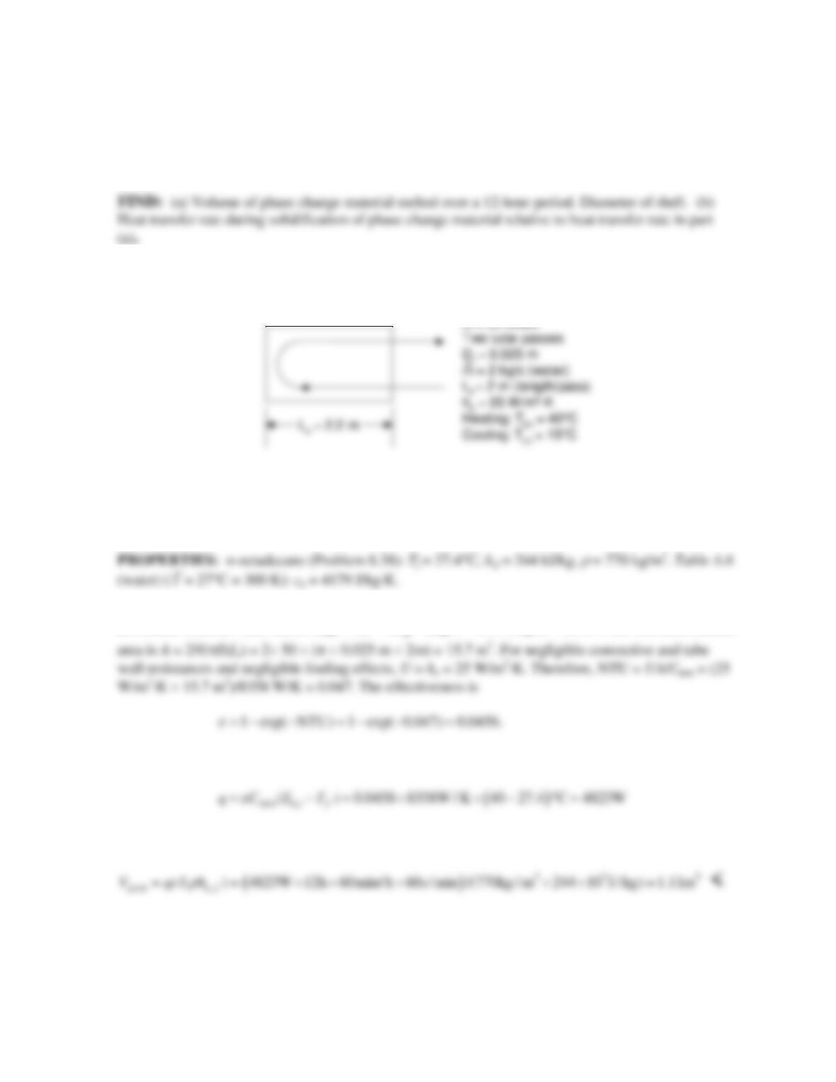
PROBLEM 11.40
KNOWN: Warm water flow rate and temperature. Cold water flow rate and temperature.
Configuration of a shell-and-tube heat exchanger including number of tube passes, number of tubes,
and tube length and tube diameter. Outside heat transfer coefficient during melting of the phase
change material. Duration of melting.
SCHEMATIC:
ASSUMPTIONS: (1) Negligible heat transfer between heat exchanger and surroundings, (2)
Negligible fouling effects, (3) Negligible wall resistance, (4) Negligible convective resistance on
inside of tubing, (5) Negligible sensible energy change in phase change material, (6) Constant
properties.
ANALYSIS: (a) With no change in the n–octadecane temperature, the minimum heat rate is
associated with the water and is Cmin = Ch =
mc
= 2kg/s × 4179 J/kg⋅K = 8358 W/K. The heat transfer
and the heat transfer rate is
Over a 12–hour period, the volume of phase change material that is melted is
so the total volume of phase change material in the shell is Vtot = 1.5×1.11 m3 = 1.66 m3 .
Continued…
Tube data
N = 50 tubes
Tube data
N = 50 tubes
PROBLEM 11.40 (Cont.)
The total shell volume is occupied by (i) phase change material and (ii) tubing. The tubing volume is
Therefore, the shell diameter is
(b) The difference between the water temperature and the melting temperature of the phase change
material is approximately 12.5 degrees Celsius for both heating and cooling modes. However, during
solidification of the phase change material, the solid phase will form adjacent to the cold tube wall.
<
COMMENTS: (1) Evaluating water properties at 40°C and for N = 50
tubes,
4 =3100
D
Re = m/(N D )
πm
,
22.2
D
Nu =
and hi = 560 W/m2∙K using the Dittus–Boelter relationship
of Chapter 8. Since hi >> ho, the assumption of negligible convection resistance on the inside of the
tube is reasonable. (2) The outlet temperature of the warm water is
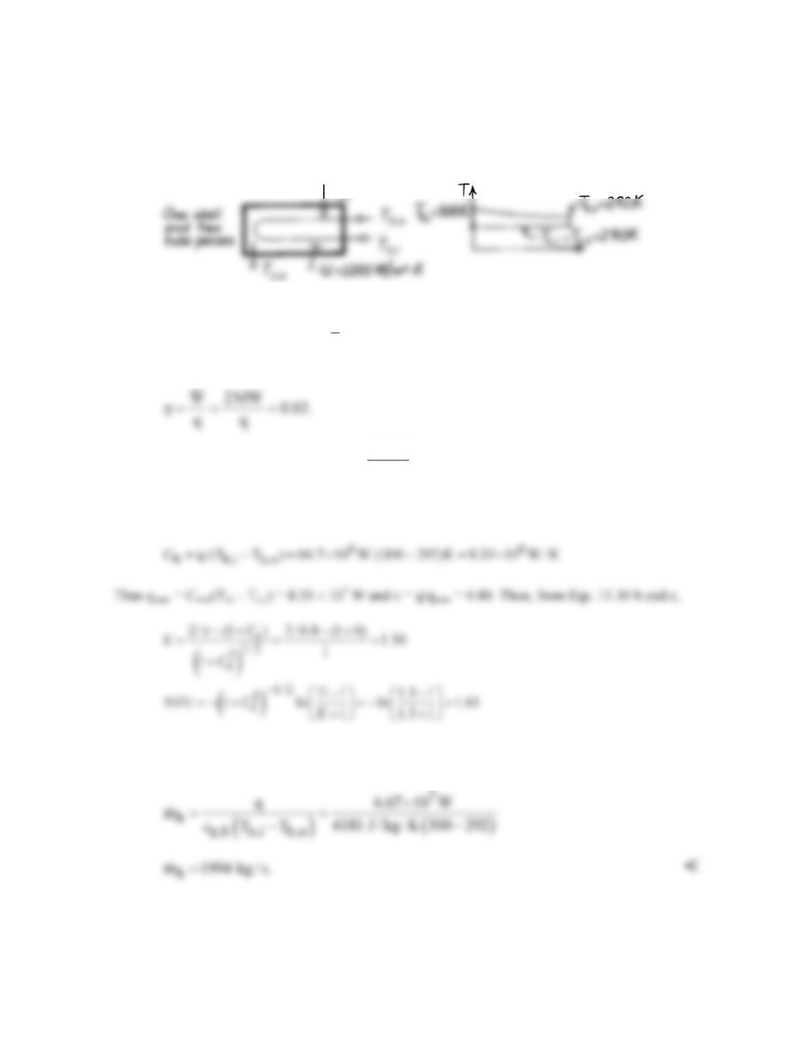
PROBLEM 11.41
KNOWN: Power output and efficiency of an ocean energy conversion system. Temperatures and
overall heat transfer coefficient of shell-and-tube evaporator.
FIND: (a) Evaporator area, (b) Water flow rate.
SCHEMATIC:
ASSUMPTIONS: (1) Negligible heat loss to surroundings, (2) Constant properties.
PROPERTIES: Table A-6, Water (
m
T
= 296 K): cp = 4181 J/kg⋅K.
ANALYSIS: (a) The efficiency is
Hence the required heat transfer rate is
2 MW
q 66.7 MW.
0.03
= =
From the ε–NTU method, Cc →∞, and Ch = Cmin can be found from an energy balance on the hot
fluid,
Then, A = NTU × Cmin /U = 1.61 × 8.33 × 106 W/K / 1200 W/m2∙K = 11,200 m2 <
(b) The water flow rate through the evaporator is
COMMENT: (1) The required heat exchanger size is enormous due to the small temperature
differences involved.
T
PROBLEM 11.42
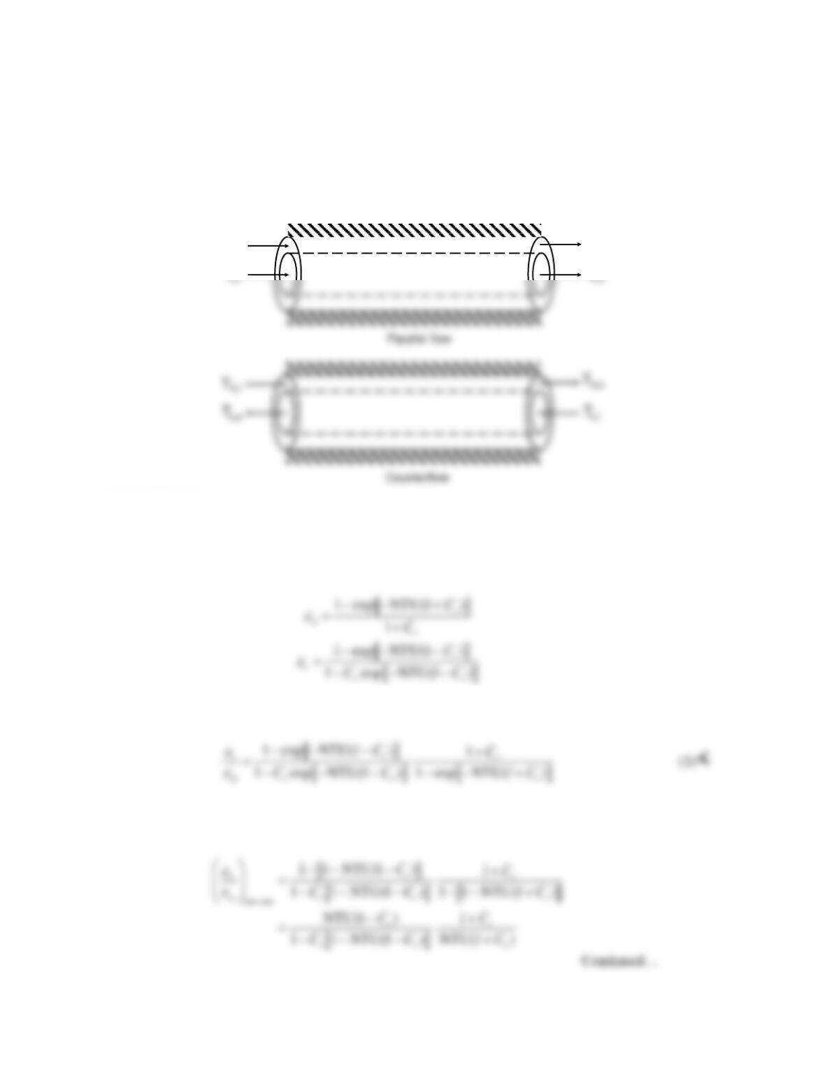
KNOWN: Parallel flow and counterflow heat exchanger.
FIND: Ratio of effectiveness values, limiting value for small area and large area heat exchangers, plot of
effectiveness ratio over the range 0 ≤ NTU ≤ 10 for Cr = 0.25, 0.5, and 0.75.Conditions for which the
counterflow mode most significantly outperforms the parallel flow mode.
SCHEMATIC:
T
T
h,i
T
h,o
T
ASSUMPTIONS: (1) Negligible heat loss to surroundings, (2) Constant properties, (3) Negligible tube
wall resistance.
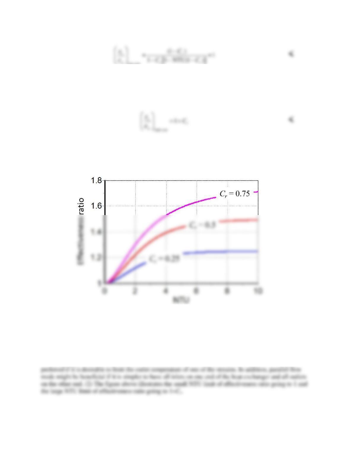
ANALYSIS: The effectiveness expressions for parallel flow and counterflow heat exchangers are given
by Equations 11.28a and 11.29a:
Thus, the ratio of effectiveness values is:
For extremely small area (low cost), NTU approaches zero, and the exponential terms can be expanded
using the first two terms of a Taylor series expansion, that is, exp(x) ≅ 1+ x. Thus,
PROBLEM 11.42 (Cont.)
low cost
In the last step, NTU has been set to zero for the small area limit.
For extremely large area (high cost), NTU approaches infinity, and the exponential terms in Eq. (1) go to
zero. Thus,
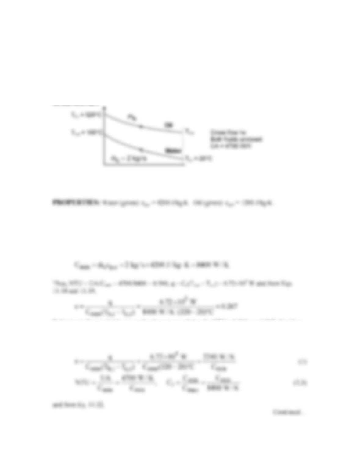
Equation (1) has been plotted over the range 0 ≤ NTU ≤ 10 for Cr = 0.25, 0.5, and 0.75 below.
The effectiveness ratio always exceeds one, since counterflow heat exchangers always outperform
parallel flow heat exchangers. The counterflow mode most outperforms the parallel flow mode for large
NTU, that is for high cost heat exchangers, especially when Cr is large. <
COMMENTS: (1) Since the parallel flow mode always perform worse than the counterflow mode, one
would usually select counterflow mode. However, in some circumstances parallel flow mode could be
PROBLEM 11.43
KNOWN: Single–pass cross-flow heat exchanger with both fluids unmixed. Flow rate and inlet
and outlet temperatures of cold water. Inlet temperature of hot exhaust gases. Value of UA.
FIND: Required mass flow rate of exhaust gases.
ASSUMPTIONS: (1) Constant properties and steady-state conditions, (2) Negligible heat loss
to surroundings, (3) U independent of mass flow rates.
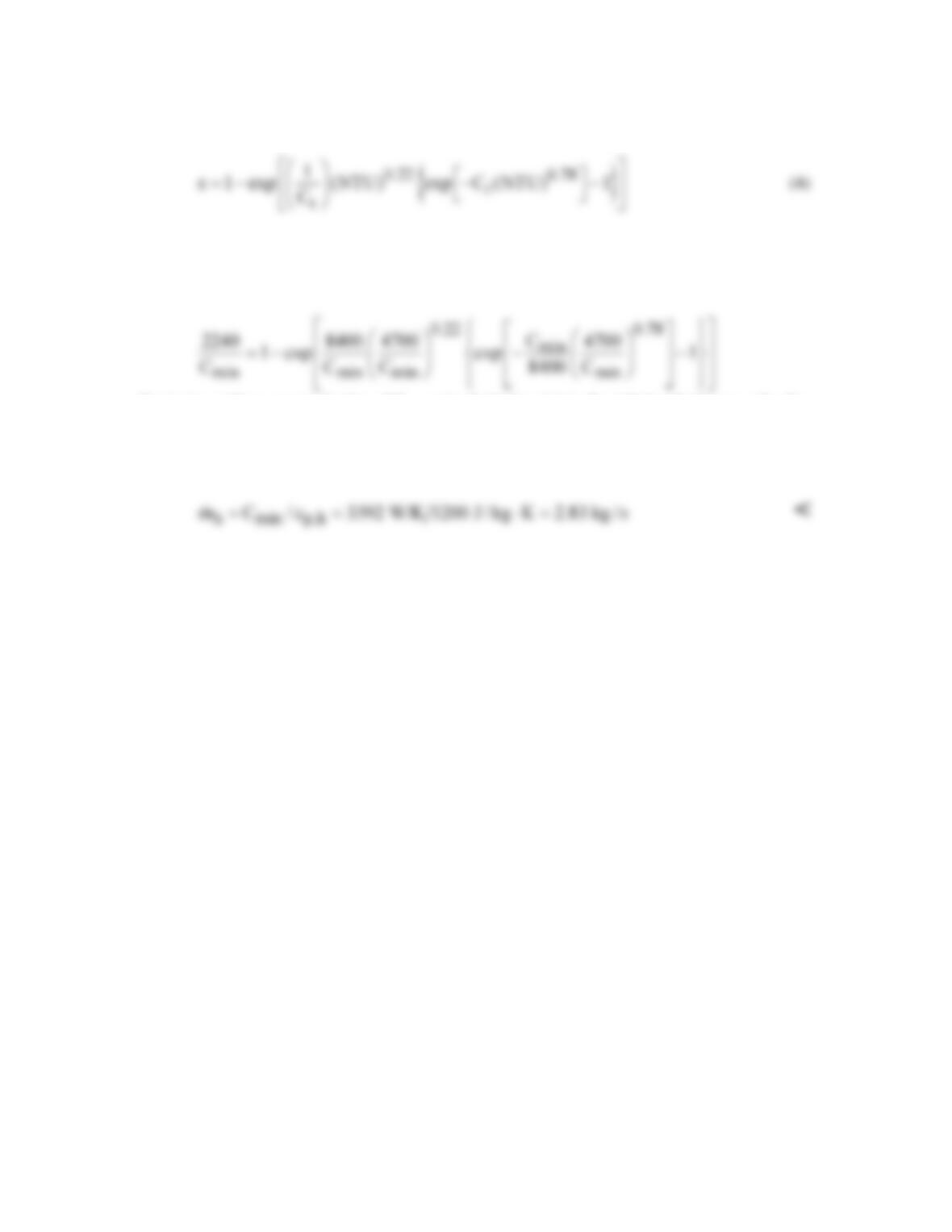
ANALYSIS: We use the ε–NTU method, but without knowing the hot mass flow rate or the hot
outlet temperature we don’t know which fluid is the minimum fluid. We begin by assuming the
cold fluid is the minimum fluid: if this leads to a solution for which the cold heat capacity rate is
indeed lower than for the hot fluid, this is the correct solution. If it does not lead to a consistent
solution, our assumption is incorrect. Thus, we assume
Referring to Figure 11.14, we see that there is no solution for NTU = 0.560, ε = 0.267, therefore
our initial assumption was incorrect and the hot fluid is the minimum fluid. We have the
following four equations relating the four unknowns ε, Cmin , NTU, and Cr,
PROBLEM 11.43 (Cont.)
These equations can be solved simultaneously using IHT, or by hand. One approach to solving
the equations by hand is as follows. Substituting Eqs. (1), (2), and (3) into Eq. (4) yields (where
the units have been omitted),
Beginning with an assumed value of Cmin and substituting it into the right hand side, we solve for
Cmin on the left hand side, and repeat the process until it converges. Beginning with Cmin = 5000,
the sequence of Cmin values is 5000, 4375, 3984, 3745, 3601, 3515, 3463, 3434, 3416, 3406,
3400, 3396, 3394, 3393, 3392, 3392. Thus
COMMENTS: It is easier to solve the system of simultaneous equations using IHT or other
non-linear equation solver.
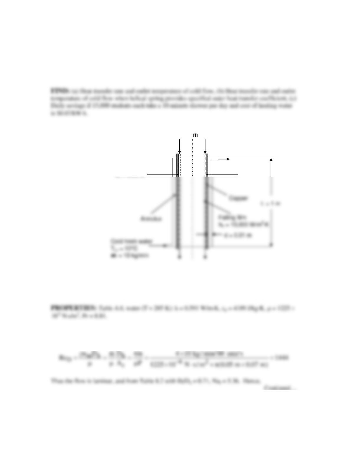
PROBLEM 11.44
KNOWN: Dimensions of counterflow, concentric tube heat exchanger for recovering heat from
shower drains. Inlet temperatures of hot and cold water streams. Heat transfer coefficient of
inner (hot) flow. Mass flow rate of outer (cold) flow.
SCHEMATIC:
ASSUMPTIONS: (1) Constant properties and steady-state conditions, (2) Negligible heat
transfer to surroundings, (3) Fully developed flow in the annular gap, (4) Uniform surface
temperature correlation is appropriate, (5) Inner tube wall thermal resistance is negligible.
ANALYSIS: (a) We begin by finding the heat transfer coefficient for the flow in the annular
gap. The Reynolds number is
Hot waste water
Th,i = 38°C, = 10 kg/min
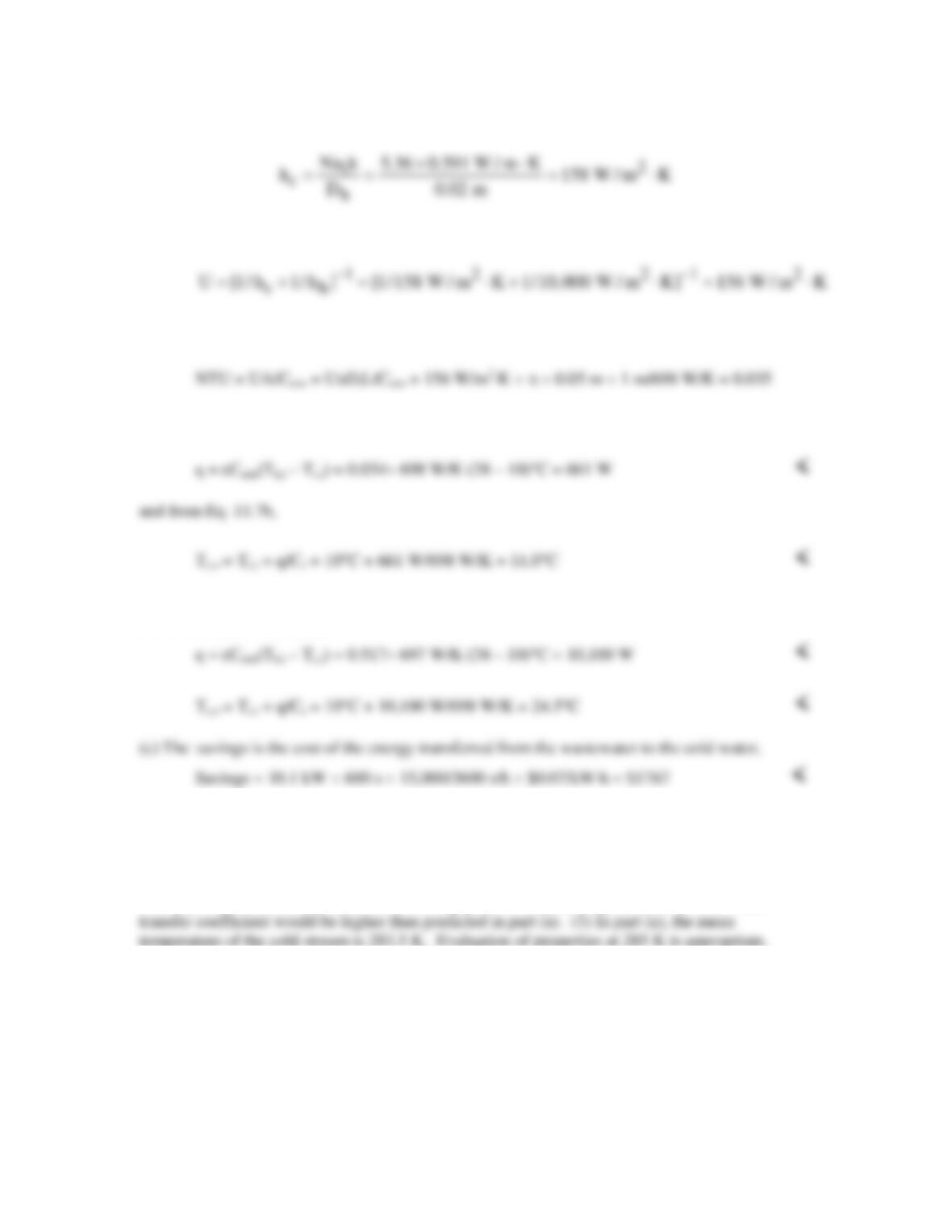
PROBLEM 11.44 (Cont.)
Then the overall heat transfer coefficient is
and using the ε–NTU method, with Cmin = Cmax =
p
mc
= 698 W/K, Cr = 1, we have
And from Eq. 11.29a, ε = NTU/(1 + NTU) = 0.034. Thus from Eqs. 11.18 and 11.19,
(b) The value of U changes to U = [1/9050 W/m2⋅K + 1/10,000 W/m2⋅K]-1 = 4751 W/K. Then
NTU = 1.07, ε = 0.517, and
COMMENTS: (1) Commercially-available devices that are used in high density buildings such
as dormitories are typically installed on larger drains that collect shower water from multiple
showers, rather than on individual showers. The devices use heat transfer enhancement
techniques to ensure large values of the cold side heat transfer coefficient. (2) With xfd,t =
0.05ReDPrDh = 13 m, the flow in the annular gap is not fully developed, and the actual heat
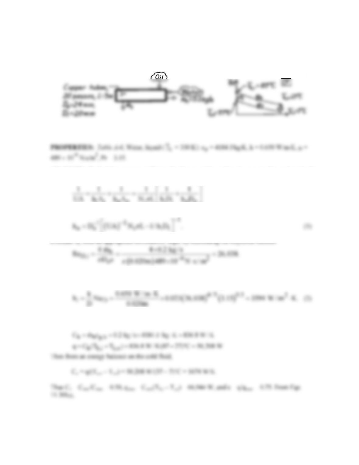
PROBLEM 11.45
KNOWN: Shell-and-tube heat exchanger with one shell pass and 20 tube passes.
FIND: Average convection coefficient for the outer tube surface.
SCHEMATIC:
ASSUMPTIONS: (1) Negligible heat loss to surroundings, (2) Constant properties, (3) Type of oil
not specified, (4) Thermal resistance of tubes negligible; no fouling.
ANALYSIS: To find the average coefficient for the outer tube surface, ho, we need to evaluate hi for
the internal tube flow and U, the overall coefficient. From Eq. 11.5,
iioo t iioo
where Nt is the total number of tubes. Solving for ho,
Hence, flow is turbulent and since L >> Di, the flow is likely to be fully developed. Use the Dittus–
Boelter correlation with n = 0.3 since Ts < Tm, NuD = 0.023
4/5
D
Re
Pr0.3
To evaluate UA, we use the ε–NTU method.
Continued…
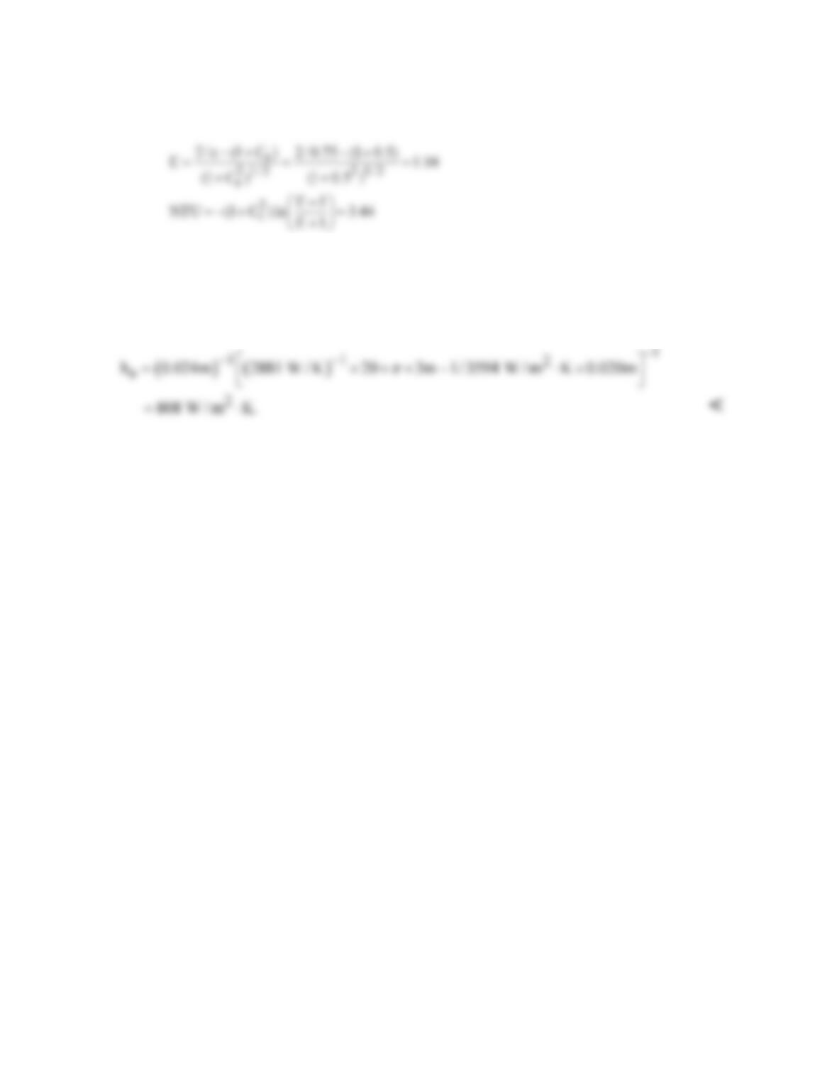
PROBLEM 11.45 (Cont.)
Therefore,
UA = NTU × Cmin = 3.44 × 836.8 W/K = 2881 W/K (3)
and