
Chapter 11 Compressible Flow
Note: Solutions presented here may refer to Isentropic
Flow Tables or Charts, Shock Tables or Charts, Fanno
Problem 11.1
Distinguish between flow of an ideal gas and inviscid flow of a fluid.
Solution 11.1
The flow of an ideal gas involves a gas that obeys the equation of state
Problem 11.2
Air flows steadily between two sections in a duct. At section (1), the temperature and
pressure are =
180 CT, =
1301kPa (abs)p, and at section (2), the temperature and pressure
are =
2180 CT, =
2181kPa (abs)p. Calculate the (a) change in internal energy between
sections (1) and (2), (b) change in enthalpy between sections (1) and (2), (c) change in
density between sections (1) and (2), (d) change in entropy between sections (1) and (2).
How would you estimate the loss of available energy between the two sections of this flow?
Solution 11.2
(a) Equation 21 21
()uucTT−= − may be used to evaluate the change in internal energy,
(b) Equation −= −
21 2 1
()
p
hhcTT
may be used to evaluate the change in enthalpy,
∨∨
−
21
hh
.
Thus,
(c) The ideal gas equation
ρ
=
p
RT may be used to evaluate the density at each section.
Thus,
(d) Equation −= −
22
21
11
ln ln
p
Tp
ssc R
Tp
may be used to evaluate the change in entropy,
or
Since the flow involves a significant change in density, see solution to part (c) above, it is
compressible and equation
ρ
−+ − =
1loss
out
out in net
uu pd q must be used to evaluating the
we get
Problem 11.3
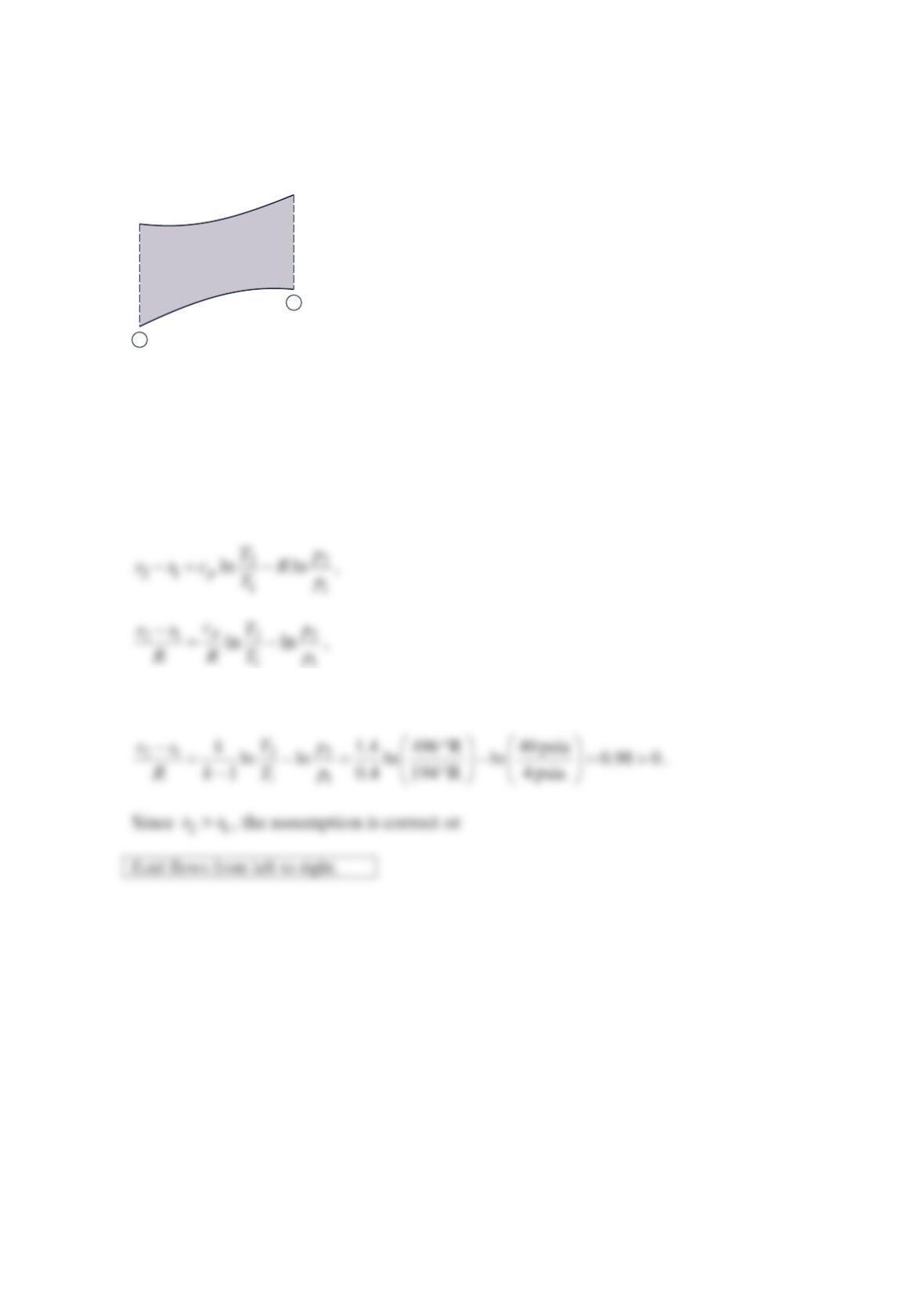
Consider the flow process in the figure below. Does the fluid flow from left to right or from
right to left? Justify your answer. Assume as ideal gas with constant specific heats.
Solution 11.3
The fluid must flow in the direction of increasing entropy. Assume the flow is from left (1)
to right (2). Then
and
Unknown flow
Ideal Gas
k = 1.4
Adiabatic, no work
p1 = 4.0 psia
V1 = 2000 ft/s
T1 = 194°R
p2 = 40.0 psia
V2 = 545 ft/s
T2 = 496°R
1
2
Problem 11.4
Fluid density differences in a flow may be seen with the help of a schlieren optical system.
Discuss what variables affect fluid density and the different ways in which a variable
density flow can be achieved.
Solution 11.4
For an ideal gas:

Problem 11.5
Describe briefly how a schlieren optical visualization system (see the figure below) works.
How else might density changes in a fluid flow be made visible to the eye?
Solution 11.5
Density variations in a transparent flowing fluid result in variations in the local speed of
light through the fluid. These light speed variations result in changes in light ray direction
Problem 11.6
Methane is compressed adiabatically from 100 kPa (abs) and 25 °C to 200 kPa (abs) . What
is the minimum compressor exit temperature possible? Explain.
Solution 11.6
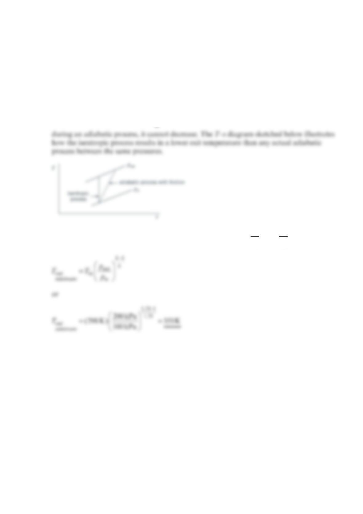
The minimum compressor exit temperature would occur with an adiabatic and frictionless
process which involves a constant entropy (i.e., isentropic flow). According to the second
law of thermodynamics,
δ
−≥0
net
Tds q , the entropy must increase or remain constant
For the isentropic compression, we conclude from −= −
22
21
11
ln ln
p
Tp
ssc R
Tp
that
Problem 11.7
Air expands adiabatically through a turbine from a pressure and temperature of
1
80 psia,
°1600 R to a pressure of 14.7 psia . If the actual temperature change is 85% of the ideal
temperature change, determine the actual temperature of the expanded air and the actual
enthalpy and entropy differences across the turbine.
Solution 11.7
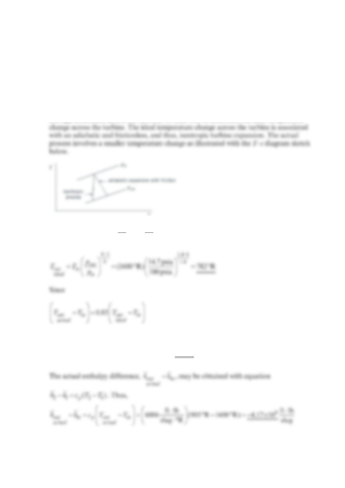
To determine the actual temperature of the expanded air and the actual enthalpy and
entropy differences across the turbine, we need first to determine the ideal temperature
Equation −= −
22
21
11
ln ln
p
Tp
ssc R
Tp
is valid for the isentropic compression. Thus,
then
=°−°+°=°0.85(782 R 1600 R) 1600 R 905 R
out
actual
T
The actual entropy difference, −
out in
actual
ss
, may be calculated with the equation
or
Problem 11.8
An expression for the value of
p
c for carbon dioxide as a function of temperature is
××
=− +
56
2
1.15 10 2.49 10
286
p
cTT
where
p
c is in ⋅
⋅
ft lb
lbm °R and T is in
°R
. Compare the change in enthalpy of carbon dioxide
using the constant value of
p
c (see Table 1.7 Approximate Physical Properties of Some
Common Gases at Standard Atmospheric Pressure [BG Units]) with the change in enthalpy
of carbon dioxide using the expression above, for −
21
TT
equal to (a) 10°R , (b) 1000°R ,
(c) 3000°R . Set =
1540°RT.
Solution 11.8
For constant
p
c, the change in enthalpy, 21
h
h−, may be evaluated with the equation
For varying
p
c, the change in enthalpy, 21
h
h−, may be evaluated with the equation
11
or
()
52
21 21
1
ft lb ft lb
286 ( ) 1.15 10 ln
lbm °R lbm
p
varying
c
T
hh TT T
⋅⋅
−= −−×
⋅
(b) For =
1540°RT and =
21540°RT
()
5
21
ft lb ft lb
152 (1540°R 540 °R) 1.52 10
lbm °R lbm
p
constant
c
hh ⋅⋅
−= −=×
⋅
and
p
c
(c) For =
1540°RT and =
23540°RT
Problem 11.9
Air flows in a 15-cm- diameter horizontal pipe. At section 1: =600 kPa,p =70 C,T and
=35 m/s.V At section 2: =42 CT and =115m/s.V Determine
(a) The pressure at section (2)
(b) The total friction force on the pipe wall
(c) The heat transfer
Solution 11.9
Assume steady flow. The continuity equation is:
The momentum equation is
Substituting values
The force on the pipe wall is equal and opposite: =
fluidonwall 10.12 kN in flow directionF
The energy equation is
−= −+ −
22
22
2222
VV
QW mh h
There is no work ( =0W) and, assuming the air is an ideal gas =
p
hcT
Problem 11.10
An air heater in a large coal-fired steam generator heats fresh air entering the steam
generator by cooling flue gas leaving the steam generator. One million lbm/hr of air at
100 °F and 1.1 millionlbm/hr of flue gas at 720 F enters the air heater. The flue gas leaves
at 310 °F. Flue gas has 0.26 Btu/lbm F
p
c= and =1.39.k Pressure changes are small and
may be neglected. Calculate the temperature of the air leaving the air heater and the total
entropy change for the process.
Solution 11.10
Air properties: =0.24 Btu/lbm F
p
c and =1.40.k
Assume (1) no shaft work; (2) steady flow; (3) negligible heat loss to the surroundings.
Gas constants Air: 0.17Btu/lbm R; 0.070Btu/lbm RcR==
Flue Gas: p0.26 0.19Btu/lbm R; 0.07 Btu/lbm R
1.39 p
c
cRcc
k
== = =−=
Problem 11.11
Determine the static pressure to stagnation pressure ratio associated with the following
motion in standard air: (a) a runner moving at the rate of 10 mph , (b) a cyclist moving at
the rate of 40 mph , (c) a car moving at the rate of 65 mph , (d) an airplane moving at the
rate of 500 mph .
Solution 11.11
With a value Mach number calculated with
We can calculate
or
(a) For =10 mphV
and
(b) For =40 mphV
(c) For =65 mphV
(d) For airplane, we assume a nominal altitude of 30,000 ft . From the Standard
Atmosphere table, we note a corresponding temperature of −47.83 F . Then
or

Then for
==
500 mph
Ma 0.738
678mph
Problem 11.12
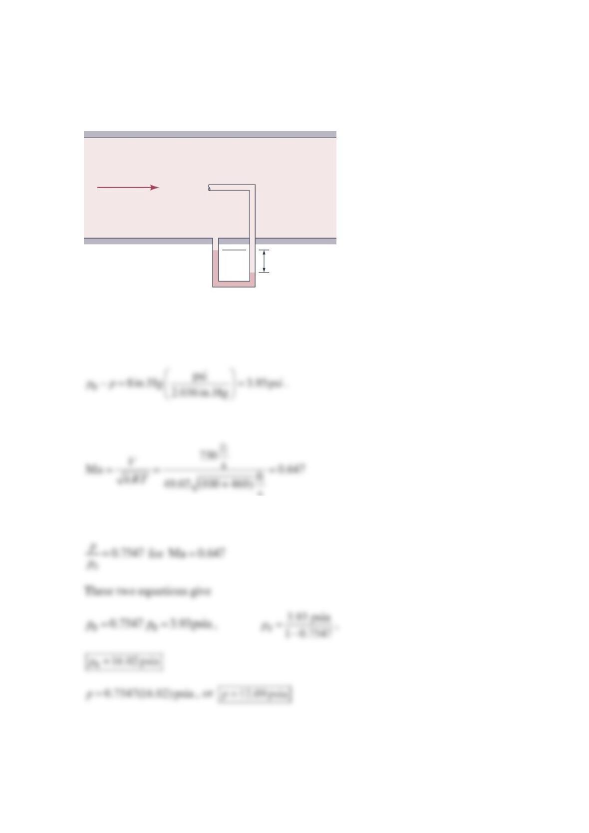
The air velocity in the duct in the figure below is 750 ft/s. The air static temperature is 100
°F. Use the mercury manometer measurement to calculate the static and stagnation
pressures of the flowing air.
Solution 11.12
Applying the manometer rule to the manometer gives
The fluid Mach number is
The Isentropic Flow Table for =1.4k (air) gives
h = 8 in.
T = 100°F
V = 750 ft/s
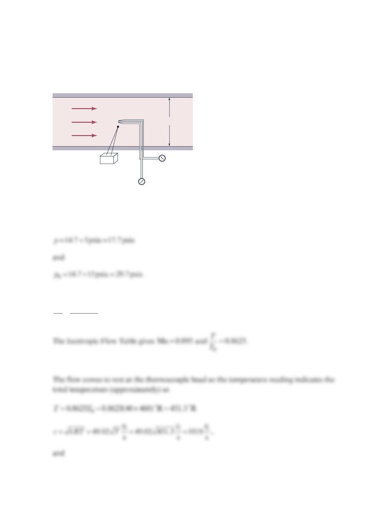
Problem 11.13
Air is flowing in a duct as shown in the figure below. A Pitot-static tube and a
thermocouple are inserted into the flow stream as shown. Calculate the air velocity and the
air-mass flowrate.
Solution 11.13
The pressure gages give
so
==
0
17.7 psia 0.5960
29.7 psia
p
p.
ps = 3 psig
p0 = 15 psig
A
= 1 ft2
40°F
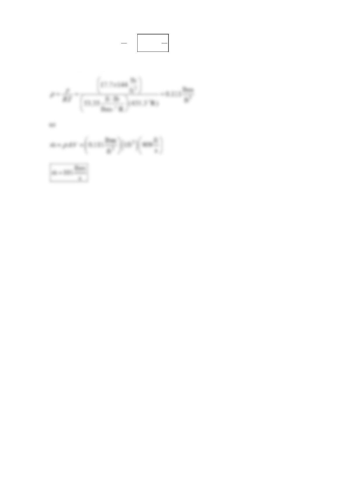
=⋅= ==
ft ft
Ma 0.893 1018 909
ss
Vc V
The ideal gas law gives