Unit 11 Solutions
Unit 11 Problem Solutions
11.1 Z responds to X and to Y after 10 ns; Y responds to
Z after 5 ns. See FLD p. 751 for answer.
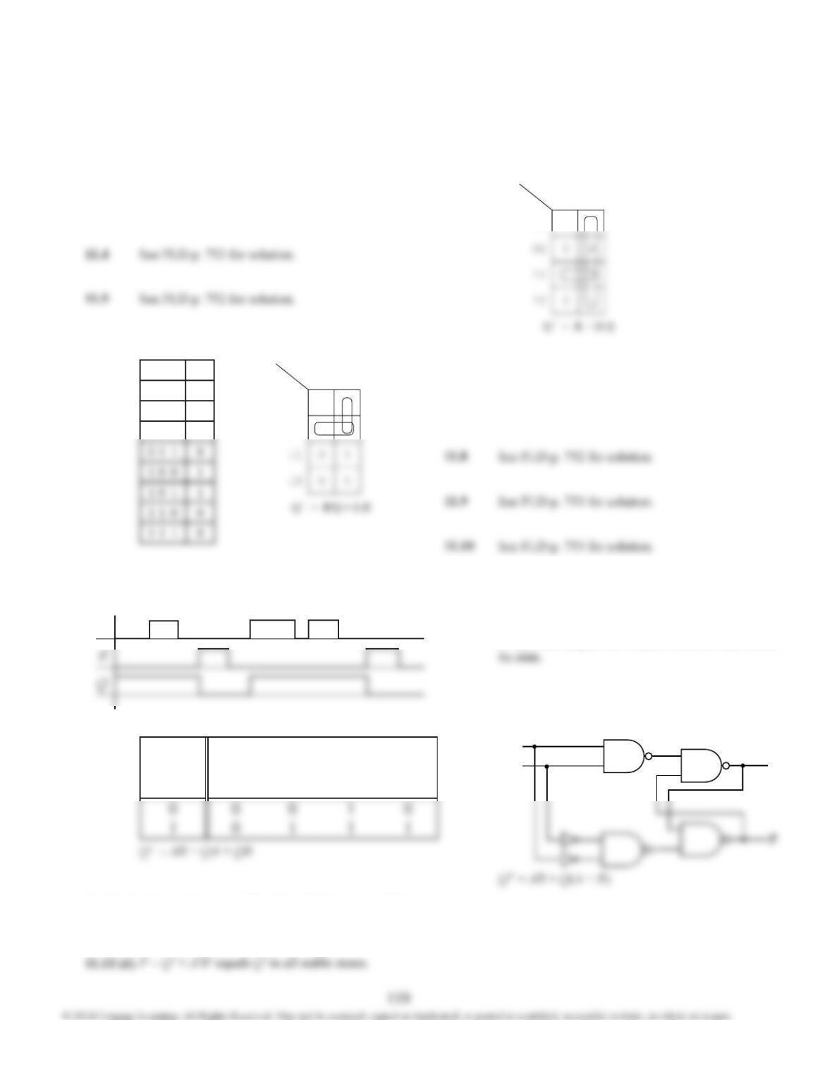
11.2 See FLD p. 751 for solution. For part (b), also use
the following Karnaugh map. Don’t cares come
from the restriction in part (a).
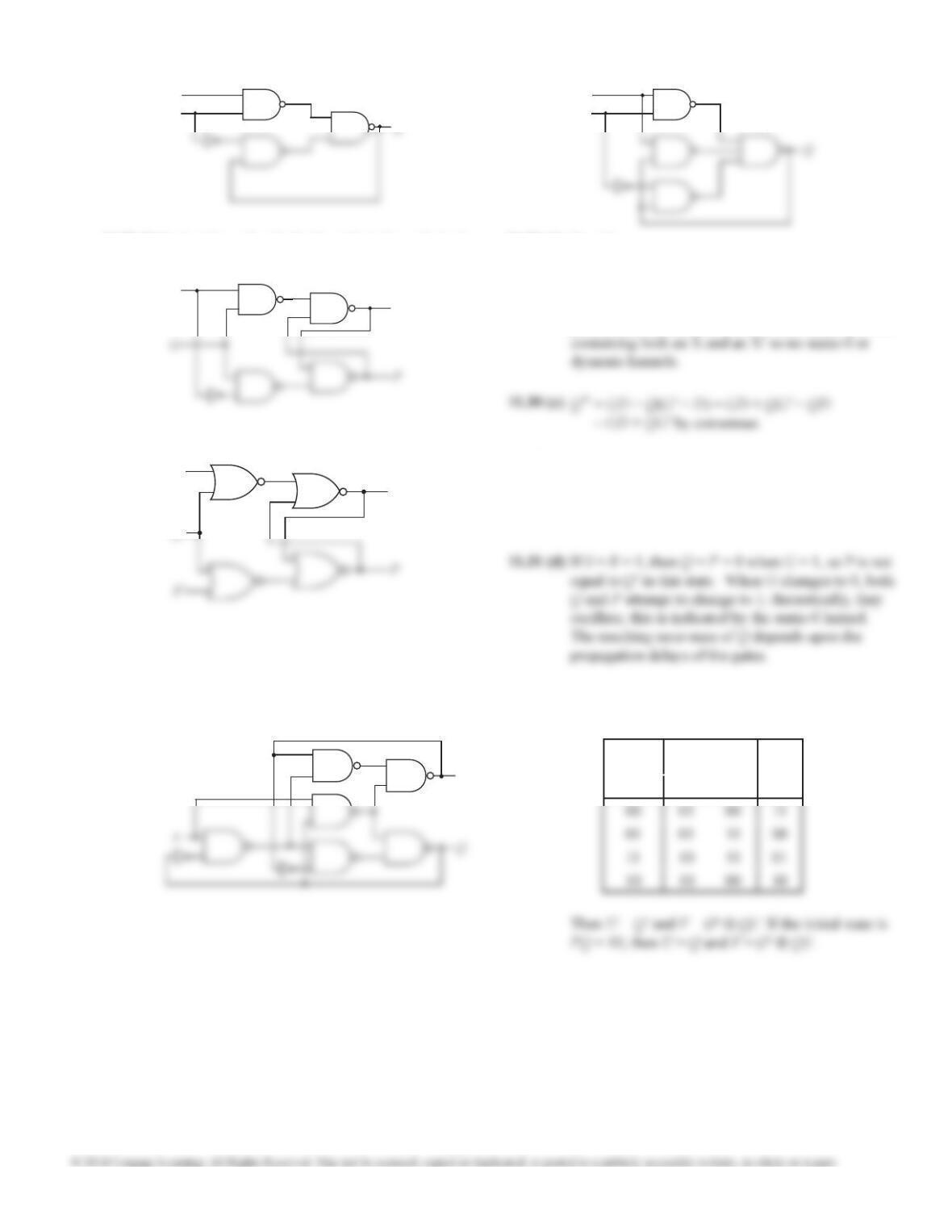
11.3 P and Q will oscillate. See FLD p. 751 for timing
chart.
11.7 See FLD p. 752 for solution.
11.12
R
H Q 0 1
00
0
X
11.6 (a) S R Q Q+
0 0 0 0
0 0 1 1
0 1 0 0
S
R Q 0 1
00
01
0
1
1
1
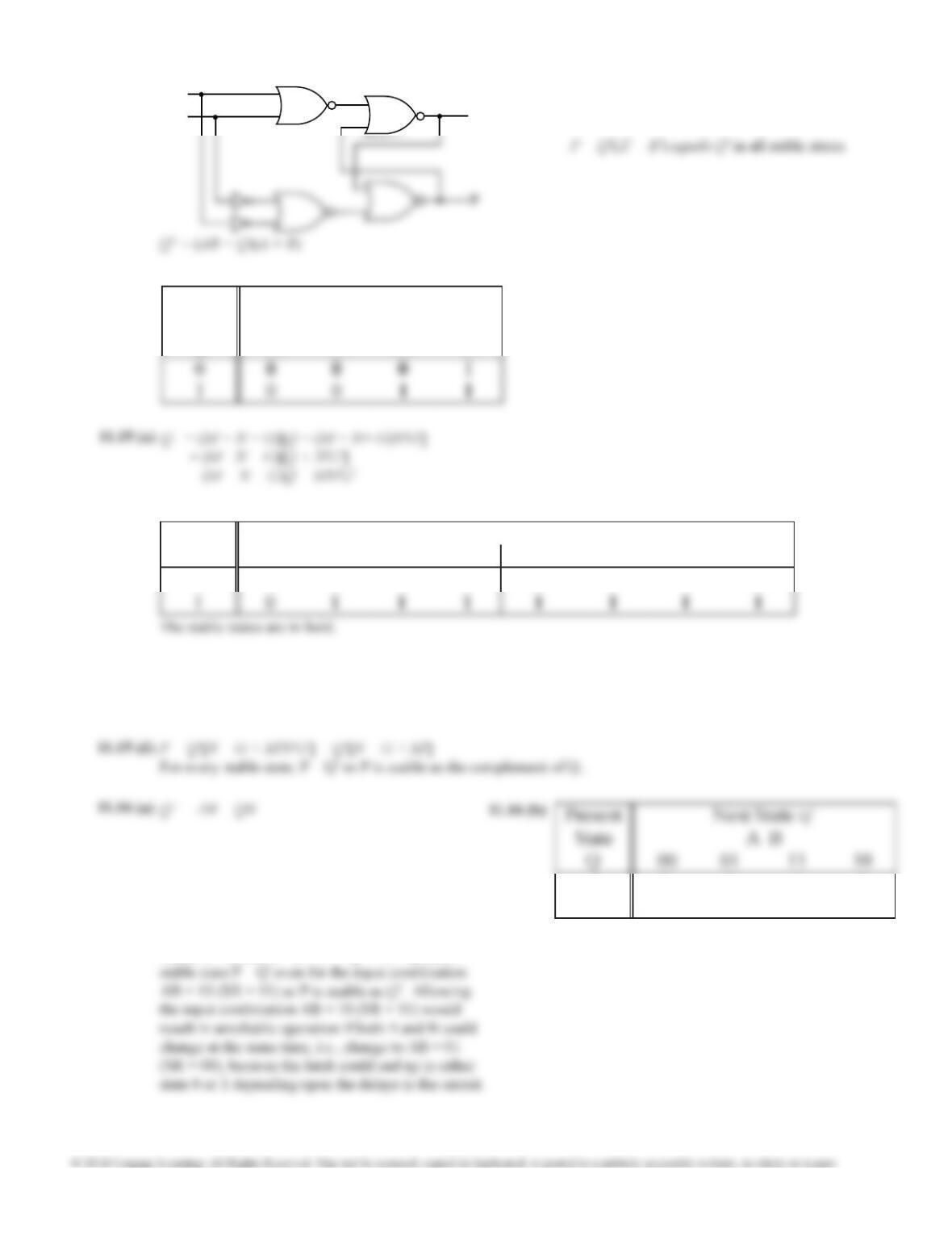
11.11
S
For every input/state combination with the
condition SR = 0 holding, each circuit obeys the
next-state equation Q+ = S + R’Q. When S = R = 1,
in (a), both outputs are 1, and in (b), the latch holds
See FLD p. 752 for solution.
11.6 (b)
11.13 (a)
A
BQ
11.13 (b)
Present
Next State
Q+
State
Q
AB
00
AB
01
AB
11
AB
10
A change between AB = 01 and 10 can cause Q to
change depending on the inverter delays.
11.13 (c)
Unit 11 Solutions
120
A
BQ
11.13 (e)
11.13 (e) A change between AB = 01 and 10 can cause Q to
change depending on the inverter delays.
Present
Next State
Q+
State A B
Q 00 01 11 10
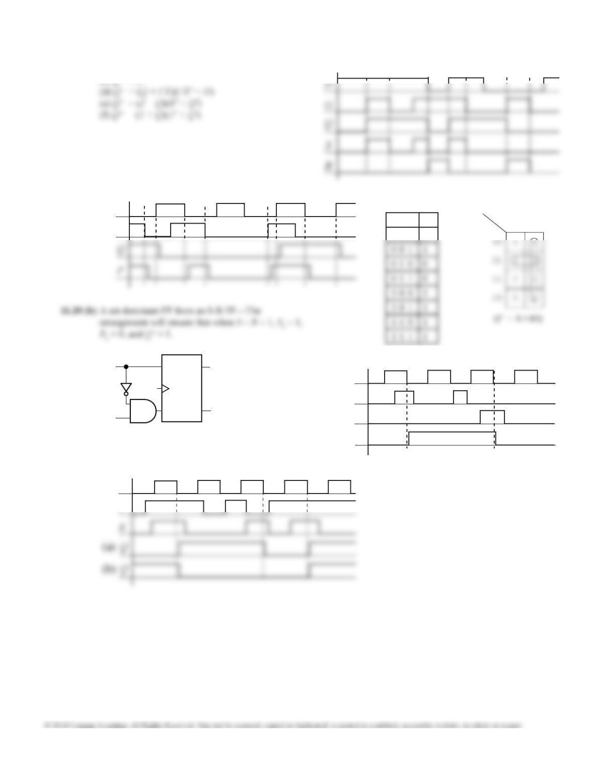
11.14 (a) Q+ = A(B’ + Q)
This is a reset dominant latch where A´ acts a reset
and B´ acts as a set.
11.15 (b)
GMN
Q 000 001 011 010 100 101 111 110
0 0 0 0 1 0 0 0 0
When G = 1, the circuit is always stable. When G = 0, M and N determine the state; N = 1 makes the state stable and
with N = 0 the state becomes the value of M. There would be a restriction on M and N if they could cause both inputs
to the output latch to be 1 when G = 0. This is not possible so there is no restriction.
11.14 b)
& (c)
11.15 (c)
0 0 0 1 0
1 0 1 1 0
The stable states are in bold.
AB = 01 is a hold input combination, AB = 00 and
10 are reset input combinations, and AB = 11 is a
set input combination. This is reset dominant latch
where S = A and R = B’. P = Q’ + B’. In each
11.16 (c)
Unit 11 Solutions
121
Clock
J
11.22 (a)
& (b)
11.19
11.21
Clock
D
S R Q Q+
0 0 0 0
11.20 (a)
R1Q’
Q
S1
CK
S
R
Clock
S
R
Q
S
R Q 0 1
11.18
(a) Q+ = R’(S + Q) if SR = 0
(b) Q+ = (G + Q)(G’ + D)
(c) Q+ = D
11.17
Unit 11 Solutions
122
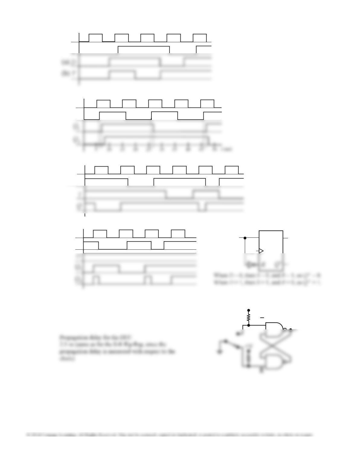
11.25 Clock
PreN
11.26
Clock
ClrN
11.27 (a)
Q
S
D
R will not be ready until D goes through the
inverter, so we must add the delay of the inverter to
the setup time:
Setup time = 1.5 + 1 = 2.5 ns
11.27 (b)
Q
S
+V
11.28
11.23 (a)
& (b) Clock
Q
11.24
Q0
Clock
Unit 11 Solutions
123
D
G
Q
11.29 (a) D
G
11.29 (c)
Static-1 hazard: (G, D, Q) = ( 0, 1, 1) ↔ (1, 1, 1) P = Q′
11.29 (b) 11.29 (d)
D
Q
11.30 (a) 11.30 (b) Q+ = GD + Q(G′ + D) = GD + QG′ + QD Each
pair of adjacent 1’s is covered by one of the
products, so no static-1 hazards. There is no product
Q
G’
R’
11.31 (a) 11.31 (b) Q+ = (G′ + R′)(Q + SG)
11.31 (c) Q+ = (G′ + R′)(Q + S)(Q + G) Static-0 hazard:
(G, S, R, Q) = (0, 1, 1, 0) ↔ (1, 1, 1, 0)
11.32 (a) P+ = x′P + xQ + PQ = (x′ + Q)P+ xQ
Q+ = x′P′ + xQ + P′Q = (x′ + Q)P′+ xQ
11.32 (b) If the initial state is PQ = 01, then the U and V
outputs are as shown in the table below.
P
Present
State
Next State
P+Q+
UV
PQ x = 0 x = 1
Unit 11 Solutions
124
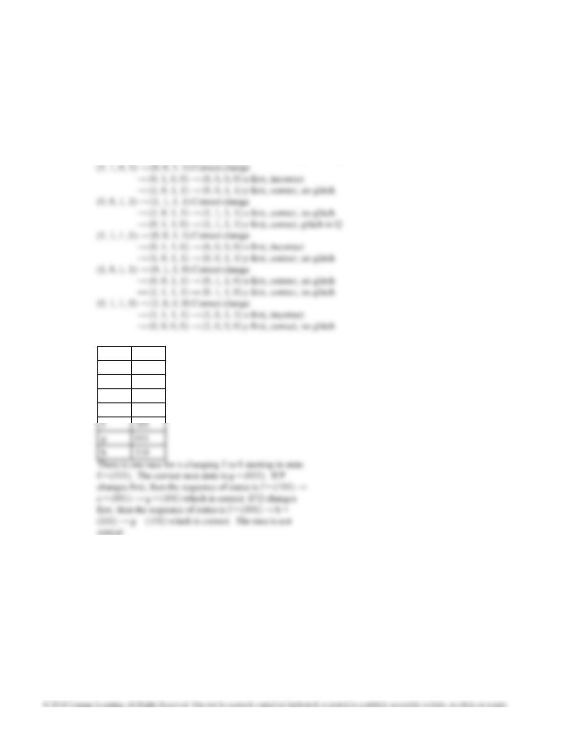
11.33 (x, y, P, Q)
(0, 0, 0, 0) → (1, 1, 0, 1) Correct change
→ (1, 0, 0, 0) → (1, 1, 0, 0) x first, correct, no glitch
→ (0, 1, 0, 0) → (1, 1, 0, 0) y first, correct, no glitch
(0, 1, 0, 0) → (1, 0, 0, 0) Correct change
→ (1, 1, 0, 1) → (1, 0, 1, 1) x first, incorrect
→ (0, 0, 0, 0) → (1, 0, 0, 0) y first, correct, no glitch
(1, 0, 0, 0) → (0, 1, 0, 0) Correct change
→ (0, 0, 0, 0) → (0, 1, 0, 0) x first, correct, no glitch
→ (1, 1, 0, 1) → (0, 1, 0, 0) y first, correct, glitch in Q
11.34 a 000
b111
c 001
d 100
e 010
critical