APPLIED FLUID MECHANICS I Power SI: CLASS I SERIES SYSTEMS
Objective: Pump power Reference points for the energy equation:
Example Problem 11.1 Point 1: At surface of lower reservoir
Fig. 11.2 Point 2: At surface of upper reservoir
System Data: SI Metric Units
Volume flow rate: Q = 0.015
m3/s Elevation at point 1 = 2.00 m
Pressure at point 1 = 0 kPa Elevation at point 2 = 12.00 m
Pressure at point 2 = 0 kPa If Ref. pt. is in pipe: Set v1 “= B20” OR Set v2 “= E20”
Velocity at point 1 = 0 m/s –> Vel head at point 1 = 0 m
Velocity at point 2 = 0 m/s –> Vel head at point 2 = 0 m
Fluid Properties: May need to compute: n = h/r
Specific weight = 7.74
kN/m 3Kinematic viscosity = 7.10E-07 m2/s
Pipe 1: 4-in Schedule 40 steel pipe Pipe 2: 2-in Schedule 40 steel pipe
Diameter: D = 0.1023 m Diameter: D = 0.0525 m
Flow Velocity = 1.82 m/s Flow Velocity = 6.93
m/s [v = Q/A]
Velocity head = 0.170 m Velocity head = 2.447
m [v2/2g ]
Reynolds No. = 2.63E+05 Reynolds No. = 5.13E+05
[NR = vD/ n]
Friction factor: f = 0.0182 Friction factor: f = 0.0198 Using Eq. 8-7
Energy losses-Pipe 1: KQty.
Pipe: K1 = f(L/D) = 2.67 1Energy loss hL1 = 0.453 m Friction
Entrance loss: K2 = 0.50 1Energy loss hL2 = 0.085 m
Energy losses-Pipe 2: KQty.
Pipe: K1 = f(L/D) = 75.35 1Energy loss hL1 = 184.40 m Friction
Globe valve: K2 = 6.46 1Energy loss hL2 = 15.81 m
2 std elbows: K3 = 0.57 2Energy loss hL3 = 2.79 m
APPLIED FLUID MECHANICS I Power US: CLASS I SERIES SYSTEMS
Objective: Pump power Reference points for the energy equation:
Problem 11.29 Pt. 1: At pump inlet – Point A in Figure 11.23
Fig. 11.26 Pt. 2: In free stream of fluid outside nozzle
System Data: U.S. Customary Units
Volume flow rate: Q = 0.5
ft 3/s Elevation at point 1 = 0 ft
Pressure at point 1 = -3.5 psig Elevation at point 2 = 80 ft
Pressure at point 2 = 0 psig
If Ref. pt. is in pipe: Set v 1 “= B20” OR Set v2 “= E20″
Pipe 1: 3-in Schedule 40 steel pipe Pipe 2: 2 1/2-in Schedule 40 steel pipe
Diameter: D = 0.2557 ft Diameter: D = 0.2058 ft
Wall roughness: e = 1.50E-04 ft Wall roughness: e = 1.50E-04 ft [See Table 8.2]
Length: L = 0ft Length: L = 82 ft
Area: A = 0.05135 ft2Area: A = 0.03326 ft2 [A = pD2/4]
D/e = 1705 D/e = 1372 Relative roughness
L/D = 0L/D = 398
Flow Velocity = 9.74 ft/s Flow Velocity = 15.03
ft/s [v = Q/A ]
Energy losses-Pipe 1:
KQty.
Pipe: K1 = 0.00 1Energy loss hL1 = 0.00 ft
Element 2: K2 = 0.00 1Energy loss hL2 = 0.00 ft
Element 3: K3 = 0.00 1Energy loss hL3 = 0.00 ft
Element 4: K4 = 0.00 1Energy loss hL4 = 0.00 ft
Element 5: K5 = 0.00 1Energy loss hL5 = 0.00 ft
Element 6: K6 = 0.00 1Energy loss hL6 = 0.00 ft
Element 7: K7 = 0.00 1Energy loss hL7 = 0.00 ft
Energy losses-Pipe 2:
KQty.
Pipe: K1 = 8.16 1Energy loss hL1 = 28.61 ft
Elbow: K2 = 0.54 1Energy loss hL2 = 1.89 ft
Nozzle: K3 = 32.60 1Energy loss hL3 = 114.37 ft
Element 4: K4 = 0.00 1Energy loss hL4 = 0.00 ft
Element 5: K5 = 0.00 1Energy loss hL5 = 0.00 ft
Element 6: K6 = 0.00 1Energy loss hL6 = 0.00 ft
Element 7: K7 = 0.00 1Energy loss hL7 = 0.00 ft
Fluid Properties: May need to compute: n = h/r
APPLIED FLUID MECHANICS I Pressure SI: CLASS I SERIES SYSTEMS
Objective: Pressure: Point 2 Reference points for the energy equation:
Problem 11.31 Pt. 1: In pipe at Point A
Fig. 11.29 Pt. 2: In pipe at Point B
System Data: SI Metric Units
Volume flow rate: Q = 3.33E-03
m3/s Elevation at point 1 = 0 m
Pressure at point 1 = 319.4 kPa Elevation at point 2 = 25 m
Pressure at point 2 = 0.00 kPa
If Ref. pt. is in pipe: Set v1 “= B20″ OR Set v2 “= E20″
Pipe 1: DN 40 Sch 40 steel pipe
Pipe 2: None
Diameter: D = 0.0409 m Diameter: D = 0.09797 m
Wall roughness: e = 4.60E-05 m Wall roughness: e = 1.50E-06 m See Table 8.2
Length: L = 27.5 mLength: L = 0 m
Energy losses-Pipe 1:
KQty.
Pipe: K1 = f(L/D) = 15.64 1Energy loss hL1 = 5.13 m Friction
Elbow: K2 = 0.60 1Energy loss hL2 = 0.20 m (fT = 0.020)
Globe Valve: K3 = 6.80 1Energy loss hL3 = 2.23 m (fT = 0.020)
Element 4: K4 = 0.00 1Energy loss hL4 = 0.00 m
Element 5: K5 = 0.00 1Energy loss hL5 = 0.00 m
Element 6: K6 = 0.00 1Energy loss hL6 = 0.00 m
Element 7: K7 = 0.00 1Energy loss hL7 = 0.00 m
Energy losses-Pipe 2:
KQty.
Pipe: K1 = f(L/D) = 0.00 1Energy loss hL1 = 0.00 m Friction
Element 2: K2 = 0.00 1Energy loss hL2 = 0.00 m
Element 3: K3 = 0.00 1Energy loss hL3 = 0.00 m
Element 4: K4 = 0.00 1Energy loss hL4 = 0.00 m
Element 5: K5 = 0.00 1Energy loss hL5 = 0.00 m
Element 6: K6 = 0.00 1Energy loss hL6 = 0.00 m
Element 7: K7 = 0.00 1Energy loss hL7 = 0.00 m
Fluid Properties: Water at 10C May need to compute: n = h/r
APPLIED FLUID MECHANICS I Pressure US: CLASS I SERIES SYSTEMS
Objective: Pressure: Point 2 Reference points for the energy equation:
Problem 11.3 Pt. 1: In pipe at Point A at outlet of pump
Fig. 11.13 Pt. 2: In pipe at Point B at inlet to the hydraulic cylinder
System Data: US Customary Units
Volume flow rate: Q = 0.13363
ft 3/s Elevation at point 1 = 0 ft
Pressure at point 1 = 212.77 psig Elevation at point 2 = 25 ft
Pressure at point 2 = 200 psig If Ref. pt. is in pipe: Set v1 “= B20″ OR Set v2 “= E20″
Pipe 1: 2-in Sch. 40 steel pipe Pipe 2: None
Diameter: D = 0.1723 ft Diameter: D = 0.1723 ft
Wall roughness: e = 1.50E-04 ft Wall roughness: e = 1.50E-04 ft See Table 8.2
Length: L = 50 ft Length: L = 0ft
Energy losses-Pipe 1: KQty.
Pipe: K1 = f(L/D) = 7.55 1Energy loss hL1 = 3.85 ft Friction
Control valve: K2 = 6.50 1Energy loss hL2 = 3.32 ft
2 elbows: K3 = 0.57 2Energy loss hL3 = 0.58 ft (fT=0.019)
Element 4: K4 = 0.00 1Energy loss hL4 = 0.00 ft
Element 5: K5 = 0.00 1Energy loss hL5 = 0.00 ft
Element 6: K6 = 0.00 1Energy loss hL6 = 0.00 ft
Element 7: K7 = 0.00 1Energy loss hL7 = 0.00 ft
Energy losses in Pipe 2: Qty.
Pipe: K1 = f(L/D) = 0.00 1Energy loss hL1 = 0.00 ft
Element 2: K2 = 0.00 1Energy loss hL2 = 0.00 ft
Element 3: K3 = 0.00 1Energy loss hL3 = 0.00 ft
Element 4: K4 = 0.00 1Energy loss hL4 = 0.00 ft
Element 5: K5 = 0.00 1Energy loss hL5 = 0.00 ft
Element 6: K6 = 0.00 1Energy loss hL6 = 0.00 ft
Element 7: K7 = 0.00 1Energy loss hL7 = 0.00 ft
Fluid Properties: May need to compute: n = h/r
APPLIED FLUID MECHANICS II-A & II-B SI: CLASS II SERIES SYSTEMS
Objective: Volume flow rate
Method II-A: No minor losses
Example Problem 11.3 Uses Equation 11-3 to estimate the allowable volume flow rate
Figure 11.7 to maintain desired pressure at point 2 for a given pressure at point 1
System Data: SI Metric Units
Pressure at point 1 = 120 kPa Elevation at point 1 = 0 m
Pressure at point 2 = 60 kPa Elevation at point 2 = 0 m
Energy loss: h L = 6.95 m
CLASS II SERIES SYSTEMS Volume flow rate: Q = 0.0538
m3/s
Method II-B: Use results of Method IIA; Given: Pressure p 1 = 120 kPa
Include minor losses;
Pressure p 2 = 60.18 kPa
then pressure at Point 2 is computed NOTE: Should be > 60 kPa
Energy losses in Pipe: KQty.
Pipe: K1 = f(L/D) = 14.76 1Energy loss hL1 = 6.26 m Friction
2 std. elbows: K2 = 0.45 2Energy loss hL2 = 0.38 m
Butterfly valve: K3 = 0.68 1Energy loss hL3 = 0.29 m
Fluid Properties: May need to compute: n = h/r
Pipe data: 6-in Schedule 40 steel pipe
APPLIED FLUID MECHANICS II-A & II-B US: CLASS II SERIES SYSTEMS
Objective: Volume flow rate
Method II-A: No minor losses
Problem 11.10 Uses Equation 11-3 to find maximum allowable volume flow rate
to maintain desired pressure at point 2 for a given pressure at point 1
System Data: US Customary Units
Pressure at point 1 = 250 psig Elevation at point 1 = 55 ft
Pressure at point 2 = 180 psig Elevation at point 2 = 0 ft
Energy loss: h L = 202.22 ft
CLASS II SERIES SYSTEMS Volume flow rate: Q = 1.45
ft 3/s
Method II-B: Use results of Method IIA; Given: Pressure p 1 = 250 psig
Include minor losses;
Pressure p 2 = 179.77 psig
then pressure at Point 2 is computed NOTE: Should be > 180 psig
Additional Pipe Data:
Adjust estimate for Q until p 2
L/D = 9766 is equal or greater than desired.
Energy losses in Pipe: KQty.
Pipe: K1 = f(L/D) = 263.18 1Energy loss hL1 = 202.69 ft Friction
Element 2: K2 = 0.00 1Energy loss hL2 = 0.00 ft
Element 3: K3 = 0.00 1Energy loss hL3 = 0.00 ft
Element 4: K4 = 0.00 1Energy loss hL4 = 0.00 ft
Element 5: K5 = 0.00 1Energy loss hL5 = 0.00 ft
Element 6: K6 = 0.00 1Energy loss hL6 = 0.00 ft
Element 7: K7 = 0.00 1Energy loss hL7 = 0.00 ft
Fluid Properties: May need to compute: n = h/r
Pipe data: 4-in Sch 40 steel pipe
APPLIED FLUID MECHANICS III-A & III-B SI: CLASS III SERIES SYSTEMS
Objective: Minimum pipe diameter Method III-A: Uses Equation 11-13 to compute the
Problem 11.18 minimum size of pipe of a given length
that will flow a given volume flow rate of fluid
System Data: SI Metric Units with a limited pressure drop. (No minor losses)
Pressure at point 1 = 150 kPa
Fluid Properties:
Pressure at point 2 = 0 kPa Specific weight = 9.53
kN/m3
Elevation at point 1 = 0 mKinematic Viscosity = 3.60E-07
m2/s
Elevation at point 2 = 0 m
Intermediate Results in Eq. 11-13:
CLASS III SERIES SYSTEMS Specified pipe diameter: D = 0.09797 m
Method III-B: Use results of Method III-A; 4-inch Type K copper tube
Specify actual diameter; Include minor losses;
If velocity is in the pipe, enter “=B23” for value
then pressure at Point 2 is computed. Velocity at point 1 = 7.96 m/s
Additional Pipe Data: Velocity at point 2 = 7.96 m/s
Flow area: A = 0.007538 m2Vel. head at point 1 = 3.229 m
Relative roughness: D/e = 65313 Vel. head at point 2 = 3.229 m
L/D = 306 Results:
Flow Velocity = 7.96 m/s Given pressure at point 1 = 150 kPa
Velocity head = 3.229 mDesired pressure at point 2 = 0 kPa
Reynolds No. = 2.17E+06
Actual pressure at point 2 = 48.13 kPa
Friction factor: f = 0.0108 (Actual p 2 should be > desired pressure)
Energy losses in Pipe: KQty.
Pipe Friction: K1 = f(L/D) = 3.31 1Energy loss hL1 = 10.69 m
Element 2: K2 = 0.00 1Energy loss hL2 = 0.00 m
Element 3: K3 = 0.00 1Energy loss hL3 = 0.00 m
Element 4: K4 = 0.00 1Energy loss hL4 = 0.00 m
Element 5: K5 = 0.00 1Energy loss hL5 = 0.00 m
Element 6: K6 = 0.00 1Energy loss hL6 = 0.00 m
Element 7: K7 = 0.00 1Energy loss hL7 = 0.00 m
APPLIED FLUID MECHANICS III-A & III-B US: CLASS III SERIES SYSTEMS
Objective: Minimum pipe diameter Method III-A: Uses Equation 11-8 to compute the
Example Problem 11.6 minimum size of pipe of a given length
that will flow a given volume flow rate of fluid
System Data: SI Metric Units with a limited pressure drop. (No minor losses)
Pressure at point 1 = 102 psig
Fluid Properties:
Pressure at point 2 = 100 psig Specific weight = 62.4
lb/ft3
If velocity is in the pipe, enter “=B23” for value
Additional Pipe Data: Velocity at point 2 = 5.66 ft/s
Reynolds No. = 1.57E+05
Actual pressure at point 2 = 100.46 psig
Friction factor: f = 0.0191 (Compare actual with desired pressure at point 2)
Energy losses in Pipe: KQty.
Pipe Friction: K1 = f(L/D) = 5.70 1Energy loss hL1 = 2.83 ft
Two long rad. elbows: K2 = 0.34 2Energy loss hL2 = 0.34 ft
Butterfly valve: K3 = 0.77 1Energy loss hL3 = 0.38 ft
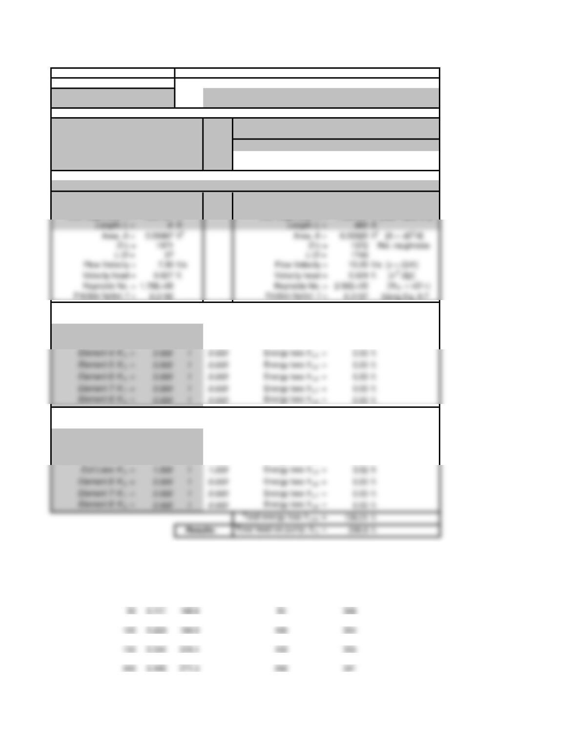
APPLIED FLUID MECHANICS System Curve US: CLASS I SERIES SYSTEMS
Objective: System Curve Reference points for the energy equation:
Ex. Problem 13.1 Pt. 1: Surface of lower reservoir
Fig. 13.33 Pt. 2: Surface of upper reservoir
System Data: U.S. Customary Units
Volume flow rate: Q = 0.5011
ft 3/s Elevation at point 1 = 0 ft
Pressure at point 1 = 0 psig Elevation at point 2 = 80 ft
Pressure at point 2 = 35 psig
If Ref. pt. is in pipe: Set v 1 “= B20” OR Set v2 “= E20“
Velocity at point 1 = 0.00 ft/s –> Vel head at point 1 = 0.00 ft
Velocity at point 2 = 0.00 ft/s –> Vel head at point 2 = 0.00 ft
Fluid Properties: May need to compute: n = h/r
Specific weight = 62.40
lb/ft 3Kinematic viscosity = 1.21E-05 ft 2/s
Pipe 1: 3 1/2-in Schedule 40 steel pipe Pipe 2: 2 1/2-in Schedule 40 steel pipe
Diameter: D = 0.2957 ft Diameter: D = 0.2058 ft
Wall roughness: e = 1.50E-04 ft Wall roughness: e = 1.50E-04 ft [See Table 8.2]
Energy losses-Pipe 1: KQty. Total K
Pipe: K1 = 0.519 1 0.519 Energy loss hL1 = 0.43 ft
Entrance: K2 = 0.500 1 0.500 Energy loss hL2 = 0.41 ft
Gate Valve: K3 = 0.136 1 0.136 Energy loss hL3 = 0.11 ft
Energy losses-Pipe 2: KQty. Total K
Pipe: K1 = 34.488 1 34.488 Energy loss hL1 = 121.53 ft
Check Valve: K2 = 1.800 1 1.800 Energy loss hL2 = 6.34 ft
Butterfly Valve: K 3 = 0.810 1 0.810 Energy loss hL3 = 2.85 ft
Standard Elbow: K4 = 0.540 2 1.080 Energy loss hL4 = 3.81 ft
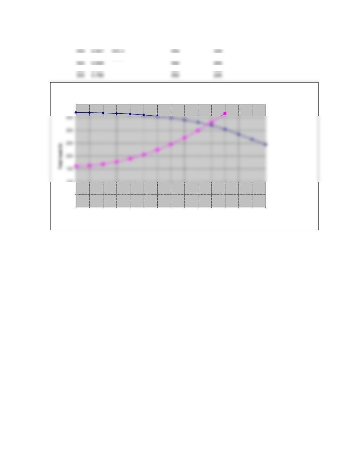
Figure 13.34 Total head on the pump at the desired operating point for Example Problem 13.1
SYSTEM CURVE PUMP CURVE: 2X3-10 PUMP WITH 9-IN IMPELLER
Q (gpm) Q (cfs) ha (ft) Q (gpm) Total head (ft)
0 0 160.8 0 370
25 0.056 162.9 25 369
75 0.167 177.6 75 366
125 0.278 205.4 125 360
175 0.390 246.1 175 349
225 0.501 299.8 225 332
275 0.612 366.3 275 305
0
50
100
400
025 50 75 100 125 150 175 200 225 250 275 300 325 350
Capacity (gal/min)
Figure 13.36 Operating Point for Example Problem 13.1
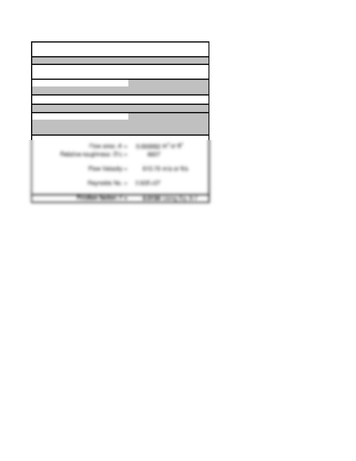
Friction Factor Calculation using Swamee-Jain Equation 8-7
Problem 8.28: Friction factor only; SI data
Use consistent SI or U.S. Customary units
Fluid Properties: Water at 75 deg C
Kinematic Viscosity 2.40E-07
m2/s or ft2/s
Volume flow rate: Q = 5.00E-02
m3/s or ft3/s
Pipe Data: 1/2 in Type K Copper
Pipe wall roughness: e = 1.50E-06 m or ft
Pipe diameter = 0.01021 m or ft
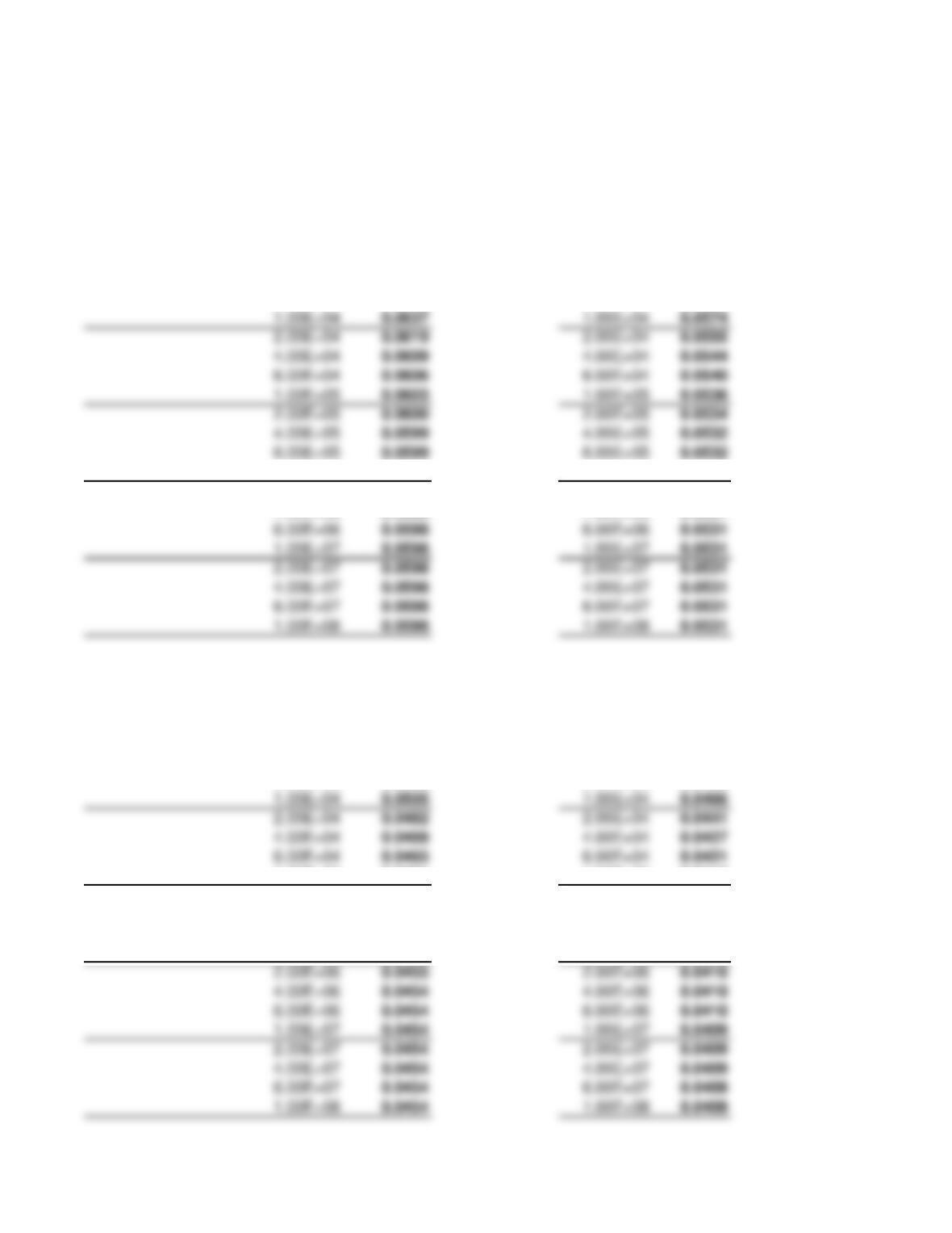
Friction factor curves
D/e30 D/e40
Friction factor Friction factor
Reynolds number f Reynolds number f
4.00E+03
0.0685 4.00E+03 0.0626
6.00E+03
0.0659 6.00E+03 0.0598
1.00E+06
0.0598 1.00E+06 0.0531
2.00E+06
0.0598 2.00E+06 0.0531
4.00E+06
0.0598 4.00E+06 0.0531
0.0598 6.00E+06 0.0531
0.0598 1.00E+07 0.0531
0.0598 2.00E+07 0.0531
0.0598 4.00E+07 0.0531
0.0598 6.00E+07 0.0531
0.0598 1.00E+08 0.0531
D/e60 D/e80
Friction factor Friction factor
Reynolds number f Reynolds number f
4.00E+03
0.0562 4.00E+03 0.0528
6.00E+03
0.0532 6.00E+03 0.0495
0.0505 1.00E+04 0.0466
0.0482 2.00E+04 0.0441
0.0469 4.00E+04 0.0427
0.0465 6.00E+04 0.0421
1.00E+05
0.0461 1.00E+05 0.0417
2.00E+05
0.0458 2.00E+05 0.0413
4.00E+05
0.0456 4.00E+05 0.0412
6.00E+05
0.0455 6.00E+05 0.0411
1.00E+06
0.0455 1.00E+06 0.0410
0.0455 2.00E+06 0.0410
0.0454 4.00E+06 0.0410
0.0454 6.00E+06 0.0410
0.0454 1.00E+07 0.0409
0.0454 2.00E+07 0.0409
0.0454 6.00E+07 0.0409
0.0454 1.00E+08 0.0409
0.0637 1.00E+04 0.0574
0.0619 2.00E+04 0.0555
0.0609 4.00E+04 0.0544
0.0606 6.00E+04 0.0540
0.0603 1.00E+05 0.0536
0.0600 2.00E+05 0.0534
0.0599 4.00E+05 0.0532
0.0599 6.00E+05 0.0532