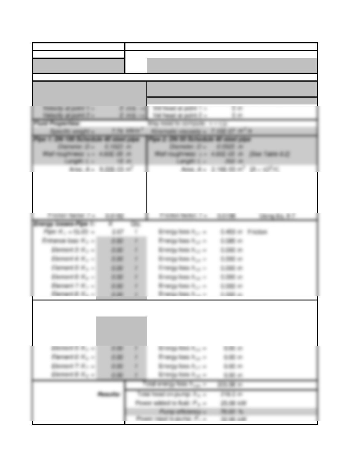
APPLIED FLUID MECHANICS I Power SI: CLASS I SERIES SYSTEMS
Objective: Pump power Reference points for the energy equation:
Example Problem 11.1 Point 1: At surface of lower reservoir
Fig. 11.2 Point 2: At surface of upper reservoir
System Data: SI Metric Units
Volume flow rate: Q = 0.015
m3/s Elevation at point 1 = 2.00 m
Pressure at point 1 = 0 kPa Elevation at point 2 = 12.00 m
Pressure at point 2 = 0 kPa If Ref. pt. is in pipe: Set v1 “= B20” OR Set v2 “= E20”
D/e = 2224 D/e = 1141 Relative roughness
L/D = 147 L/D = 3810
Flow Velocity = 1.82 m/s Flow Velocity = 6.93
m/s [v = Q/A]
Velocity head = 0.170 m Velocity head = 2.447
m [v2/2g ]
Reynolds No. = 2.63E+05 Reynolds No. = 5.13E+05
[NR = vD/ n]
Energy losses-Pipe 1: KQty.
Pipe: K1 = f(L/D) = 2.67 1Energy loss hL1 = 0.453 m Friction
Energy losses-Pipe 2: KQty.
Pipe: K1 = f(L/D) = 75.35 1Energy loss hL1 = 184.40 m Friction
Globe valve: K2 = 6.46 1Energy loss hL2 = 15.81 m
2 std elbows: K3 = 0.57 2Energy loss hL3 = 2.79 m
Exit loss: K4 = 1.00 1Energy loss hL4 = 2.45 m
Fluid Properties: May need to compute: n = h/r
Pipe 1: DN 100 Schedule 40 steel pipe Pipe 2: DN 50 Schedule 40 steel pipe
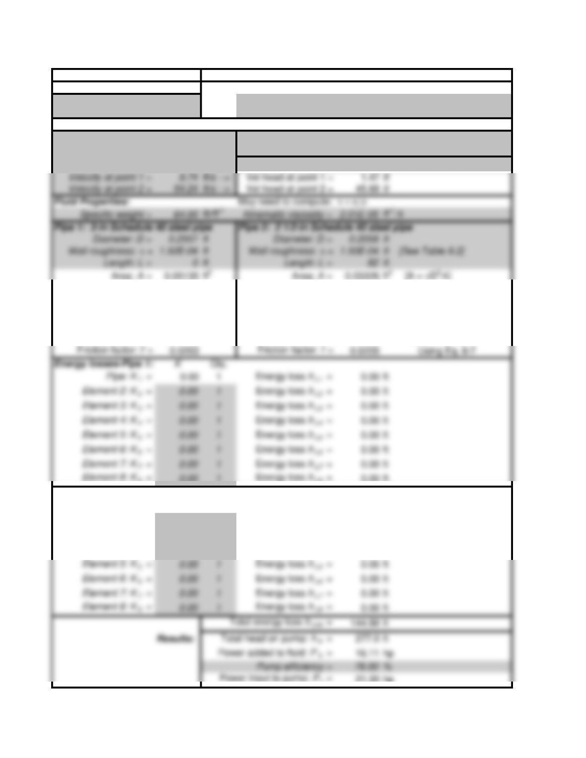
APPLIED FLUID MECHANICS I Power US: CLASS I SERIES SYSTEMS
Objective: Pump power Reference points for the energy equation:
Problem 11.29 Pt. 1: At pump inlet – Point A in Figure 11.28
Fig. 11.28 Pt. 2: In free stream of fluid outside nozzle
System Data: U.S. Customary Units
Volume flow rate: Q = 0.5
ft 3/s Elevation at point 1 = 0 ft
Pressure at point 1 = –3.5 psig Elevation at point 2 = 80 ft
Pressure at point 2 = 0 psig
If Ref. pt. is in pipe: Set v 1 “= B20” OR Set v2 “= E20″
D/e = 1705 D/e = 1372 Relative roughness
L/D = 0L/D = 398
Flow Velocity = 9.74 ft/s Flow Velocity = 15.03
ft/s [v = Q/A ]
Velocity head = 1.472 ft Velocity head = 3.508
ft [v2/2g ]
Reynolds No. = 1.24E+05 Reynolds No. = 1.54E+05
[NR = vD/ n]
Energy losses-Pipe 1:
Pipe: K1 = 0.00 1Energy loss hL1 = 0.00 ft
Element 2: K2 = 0.00 1Energy loss hL2 = 0.00 ft
Element 3: K3 = 0.00 1Energy loss hL3 = 0.00 ft
Element 4: K4 = 0.00 1Energy loss hL4 = 0.00 ft
Element 5: K5 = 0.00 1Energy loss hL5 = 0.00 ft
Element 6: K6 = 0.00 1Energy loss hL6 = 0.00 ft
Element 7: K7 = 0.00 1Energy loss hL7 = 0.00 ft
Energy losses-Pipe 2:
KQty.
Pipe: K1 = 8.16 1Energy loss hL1 = 28.61 ft
Elbow: K2 = 0.54 1Energy loss hL2 = 1.89 ft – fT = 0.018
Nozzle: K3 = 32.60 1Energy loss hL3 = 114.37 ft – based on discharge line
Element 4: K4 = 0.00 1Energy loss hL4 = 0.00 ft
Element 5: K5 = 0.00 1Energy loss hL5 = 0.00 ft
Element 6: K6 = 0.00 1Energy loss hL6 = 0.00 ft
Element 7: K7 = 0.00 1Energy loss hL7 = 0.00 ft
Fluid Properties: May need to compute: n = h/r
Pipe 1: 3-in Schedule 40 steel pipe Pipe 2: 2 1/2-in Schedule 40 steel pipe
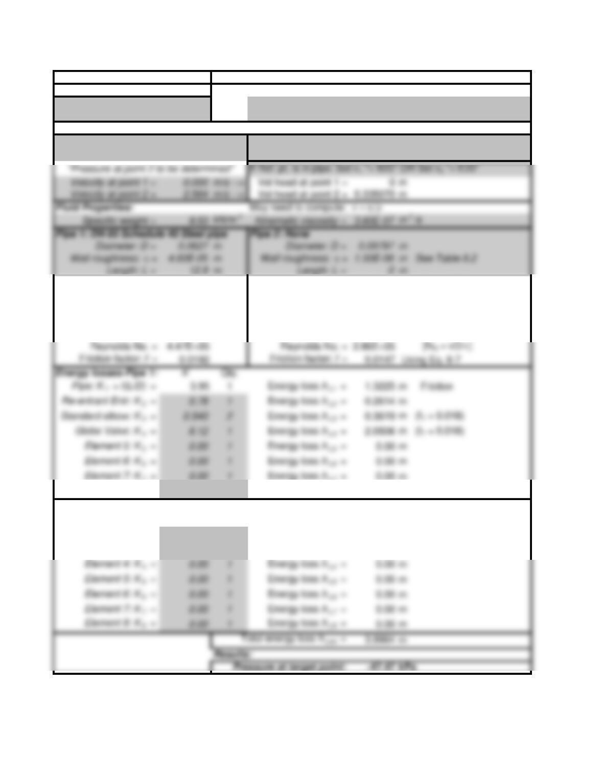
APPLIED FLUID MECHANICS I Pressure SI: CLASS I SERIES SYSTEMS
Objective: Pressure: Point 2 Reference points for the energy equation:
Problem 11.27 Pt. 1: At reservoir surface
Fig. 11.27 Pt. 2: In pipe at pump inlet
System Data: SI Metric Units
Volume flow rate: Q = 7.917E-03
m3/s Elevation at point 1 = 0.75 m
Pressure at point 1 = 0 kPa Elevation at point 2 = 1.4 m
Area: A = 3.088E-03 m2Area: A = 7.54E-03 m2 [A = pD2/4]
D/e = 1363 D/e = 65313 Relative roughness
L/D = 206 L/D = 0
Energy losses-Pipe 1:
Pipe: K1 = f(L/D) = 3.95 1Energy loss hL1 = 1.3225 m Friction
Element 5: K5 = 0.00 1Energy loss hL5 = 0.00 m
Element 6: K6 = 0.00 1Energy loss hL6 = 0.00 m
Element 7: K7 = 0.00 1Energy loss hL7 = 0.00 m
Flow Velocity = 2.564 m/s Flow Velocity = 1.0502 m/s [v = Q/A]
Velocity head = 0.335070 m Velocity head = 0.0562 m
Element 8: K8 = 0.00 1Energy loss hL8 = 0.00 m
Energy losses-Pipe 2:
KQty.
Pipe: K1 = f(L/D) = 0.00 1Energy loss hL1 = 0.00 m Friction
Element 2: K2 = 0.00 1Energy loss hL2 = 0.00 m
Element 3: K3 = 0.00 1Energy loss hL3 = 0.00 m
Element 4: K4 = 0.00 1Energy loss hL4 = 0.00 m
Element 5: K5 = 0.00 1Energy loss hL5 = 0.00 m
Element 6: K6 = 0.00 1Energy loss hL6 = 0.00 m
Element 7: K7 = 0.00 1Energy loss hL7 = 0.00 m
Element 8: K8 = 0.00 1Energy loss hL8 = 0.00 m
Fluid Properties: May need to compute: n = h/r
Pipe 1: DN 65 Schedule 40 Steel pipe Pipe 2: None
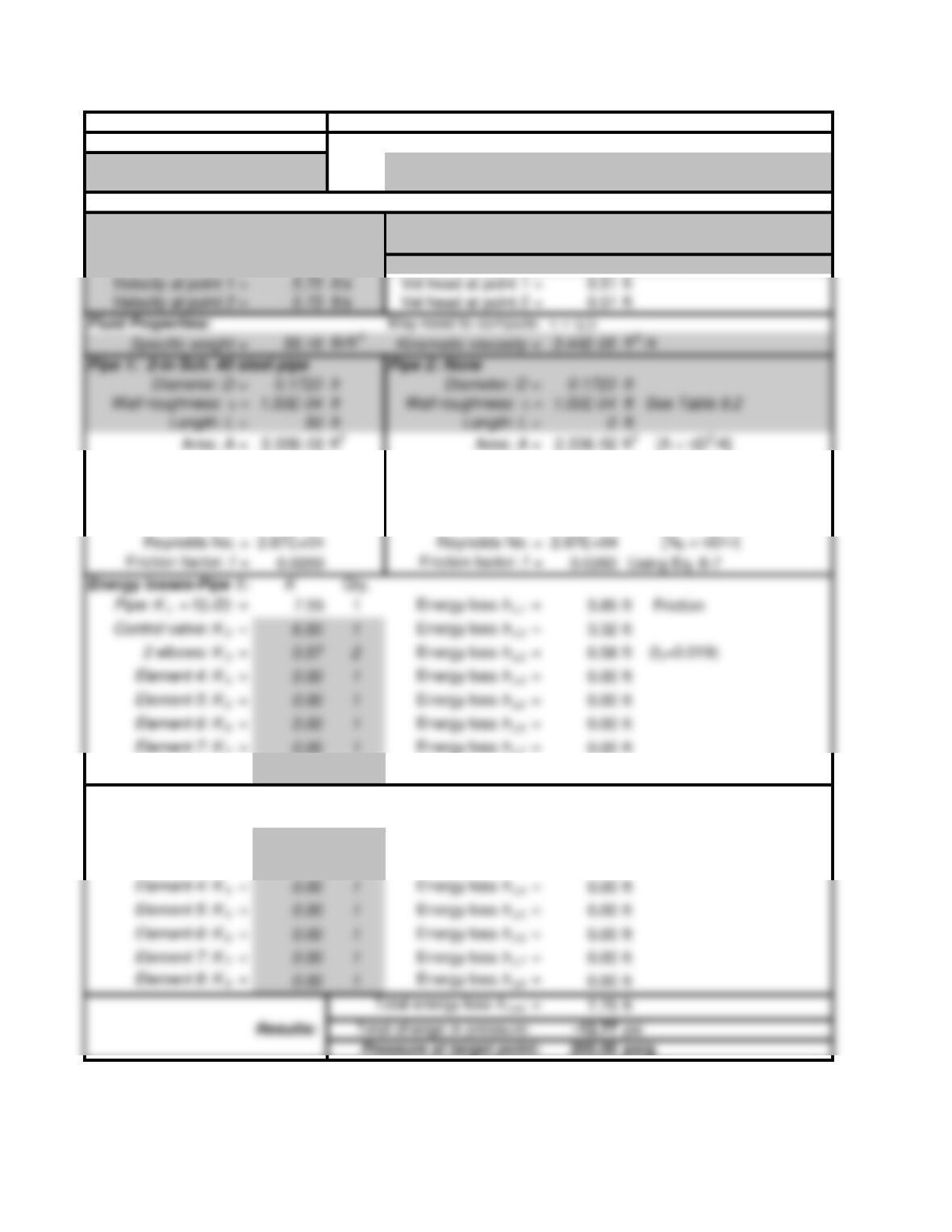
APPLIED FLUID MECHANICS I Pressure US: CLASS I SERIES SYSTEMS
Objective: Pressure: Point 2 Reference points for the energy equation:
Problem 11.27 Pt. 1: At reservoir surface
Fig. 11.27 Pt. 2: In pipe at inlet to the pump
System Data: US Customary Units
Volume flow rate: Q = 0.13363
ft 3/s Elevation at point 1 = 0 ft
Pressure at point 1 = 212.77 psig Elevation at point 2 = 25 ft
Pressure at point 2 = 200 psig If Ref. pt. is in pipe: Set v1 “= B20″ OR Set v2 “= E20″
D/e = 1149 D/e = 1149 Relative roughness
L/D = 290 L/D = 0
Energy losses-Pipe 1: KQty.
Pipe: K1 = f(L/D) = 7.55 1Energy loss hL1 = 3.85 ft Friction
Element 4: K4 = 0.00 1Energy loss hL4 = 0.00 ft
Element 5: K5 = 0.00 1Energy loss hL5 = 0.00 ft
Element 6: K6 = 0.00 1Energy loss hL6 = 0.00 ft
Element 7: K7 = 0.00 1Energy loss hL7 = 0.00 ft
Flow Velocity = 5.73 ft/s Flow Velocity = 5.73 ft/s [v = Q/A]
Velocity head = 0.510 ft Velocity head = 0.510 ft [v2/2g]
Element 8: K8 = 0.00 1Energy loss hL8 = 0.00 ft
Energy losses in Pipe 2: Qty.
Pipe: K1 = f(L/D) = 0.00 1Energy loss hL1 = 0.00 ft
Element 2: K2 = 0.00 1Energy loss hL2 = 0.00 ft
Element 3: K3 = 0.00 1Energy loss hL3 = 0.00 ft
Element 4: K4 = 0.00 1Energy loss hL4 = 0.00 ft
Element 5: K5 = 0.00 1Energy loss hL5 = 0.00 ft
Element 6: K6 = 0.00 1Energy loss hL6 = 0.00 ft
Element 7: K7 = 0.00 1Energy loss hL7 = 0.00 ft
Element 8: K8 = 0.00 1Energy loss hL8 = 0.00 ft
Fluid Properties: May need to compute: n = h/r
Pipe 1: 2-in Sch. 40 steel pipe Pipe 2: None
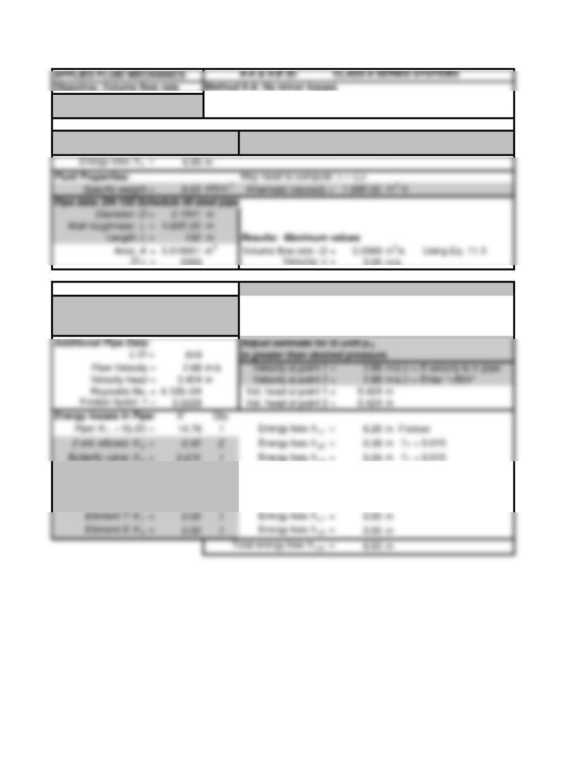
Example Problem 11.3 Uses Equation 11-3 to estimate the allowable volume flow rate
Figure 11.7 to maintain desired pressure at point 2 for a given pressure at point 1
System Data: SI Metric Units
Pressure at point 1 = 120 kPa Elevation at point 1 = 0 m
Pressure at point 2 = 60 kPa Elevation at point 2 = 0 m
CLASS II SERIES SYSTEMS Volume flow rate: Q = 0.0538
m3/s
Method II-B: Use results of Method IIA; Given: Pressure p 1 = 120 kPa
Include minor losses;
Pressure p 2 = 60.18 kPa
then pressure at Point 2 is computed NOTE: Should be > 60 kPa
Element 4: K4 = 0.00 1Energy loss hL4 = 0.00 m
Element 5: K5 = 0.00 1Energy loss hL5 = 0.00 m
Element 6: K6 = 0.00 1Energy loss hL6 = 0.00 m
Element 7: K7 = 0.00 1Energy loss hL7 = 0.00 m
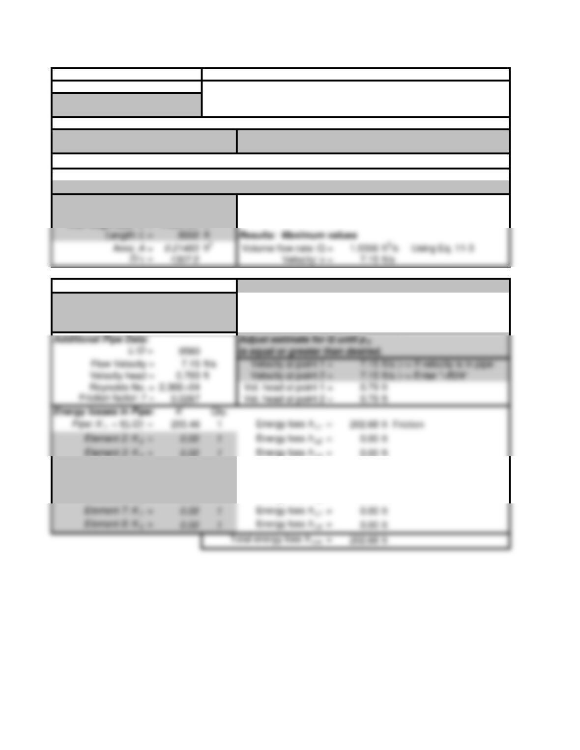
APPLIED FLUID MECHANICS II-A & II-B US: CLASS II SERIES SYSTEMS
Objective: Volume flow rate
Method II-A: No minor losses
Problem 11.10 Uses Equation 11-3 to find maximum allowable volume flow rate
to maintain desired pressure at point 2 for a given pressure at point 1
System Data: US Customary Units
Pressure at point 1 = 250 psig Elevation at point 1 = 55 ft
Pressure at point 2 = 180 psig Elevation at point 2 = 0 ft
Energy loss: h L = 202.22 ft
Fluid Properties: Eth. Glycol: 77F May need to compute: n = h/r
Specific weight = 68.47
lb/ft 3Kinematic viscosity = 1.59E-04 ft 2/s
Pipe data: 6-in ductile iron pipe
Diameter: D = 0.523 ft
Wall roughness:
e
= 4.00E-04 ft
CLASS II SERIES SYSTEMS Volume flow rate: Q = 1.5356
ft 3/s
Method II-B: Use results of Method IIA; Given: Pressure p 1 = 250 psig
Include minor losses;
Pressure p 2 = 179.78 psig
then pressure at Point 2 is computed NOTE: Should be > 180 psig
Energy losses in Pipe: KQty.
Element 2: K2 = 0.00 1Energy loss hL2 = 0.00 ft
Element 3: K3 = 0.00 1Energy loss hL3 = 0.00 ft
Element 4: K4 = 0.00 1Energy loss hL4 = 0.00 ft
Element 5: K5 = 0.00 1Energy loss hL5 = 0.00 ft
Element 6: K6 = 0.00 1Energy loss hL6 = 0.00 ft
Element 7: K7 = 0.00 1Energy loss hL7 = 0.00 ft
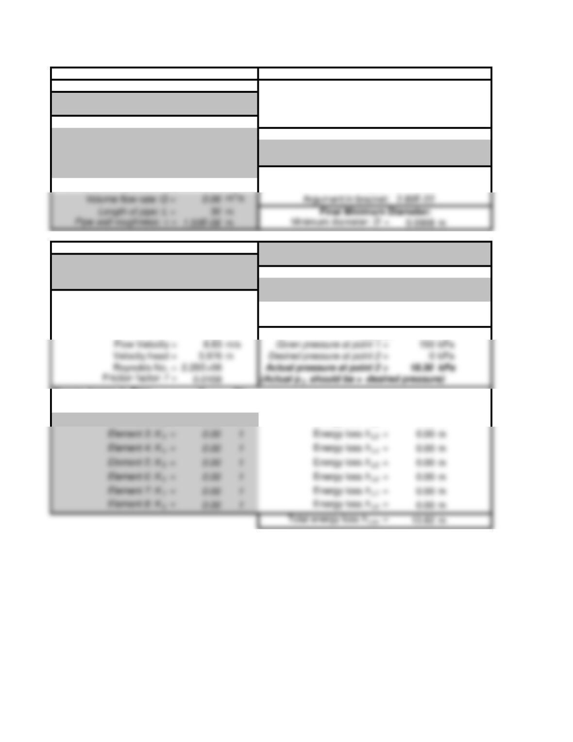
APPLIED FLUID MECHANICS III-A & III-B SI: CLASS III SERIES SYSTEMS
Objective: Minimum pipe diameter Method III-A: Uses Equation 11-13 to compute the
Problem 11.18 minimum size of pipe of a given length
that will flow a given volume flow rate of fluid
System Data: SI Metric Units with a limited pressure drop. (No minor losses)
Pressure at point 1 = 150 kPa
Fluid Properties:
Pressure at point 2 = 0 kPa Specific weight = 9.53
kN/m3
Elevation at point 1 = 0 mKinematic Viscosity = 3.60E-07
m2/s
Elevation at point 2 = 0 m
Intermediate Results in Eq. 11-13:
Allowable Energy Loss: hL = 15.74 mL/ghL = 0.194292
CLASS III SERIES SYSTEMS Specified pipe diameter: D = 0.093 m
Method III-B: Use results of Method III-A; 100 mm OD × 3.5 mm wall copper tube; App. G.2
Specify actual diameter; Include minor losses;
If velocity is in the pipe, enter “=B23” for value
then pressure at Point 2 is computed. Velocity at point 1 = 8.83 m/s
Additional Pipe Data: Velocity at point 2 = 8.83 m/s
Flow area: A = 0.006793 m2Vel. head at point 1 = 3.976 m
Relative roughness: D/e = 62000 Vel. head at point 2 = 3.976 m
L/D = 323 Results:
Energy losses in Pipe: KQty.
Pipe Friction: K1 = f(L/D) = 3.48 1Energy loss hL1 = 13.82 m
Element 2: K2 = 0.00 1Energy loss hL2 = 0.00 m
Element 3: K3 = 0.00 1Energy loss hL3 = 0.00 m
Element 4: K4 = 0.00 1Energy loss hL4 = 0.00 m
Element 5: K5 = 0.00 1Energy loss hL5 = 0.00 m
Element 6: K6 = 0.00 1Energy loss hL6 = 0.00 m
Element 7: K7 = 0.00 1Energy loss hL7 = 0.00 m
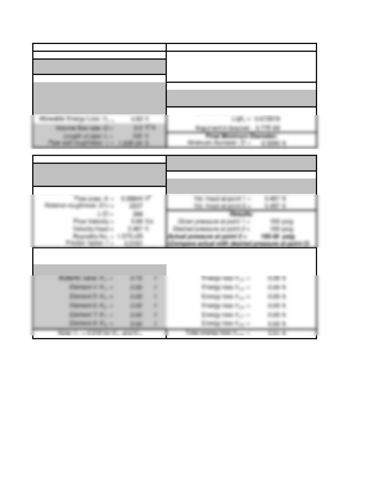
APPLIED FLUID MECHANICS III-A & III-B US: CLASS III SERIES SYSTEMS
Objective: Minimum pipe diameter Method III-A: Uses Equation 11-8 to compute the
Example Problem 11.6 minimum size of pipe of a given length
that will flow a given volume flow rate of fluid
System Data: SI Metric Units with a limited pressure drop. (No minor losses)
Pressure at point 1 = 102 psig
Fluid Properties:
Pressure at point 2 = 100 psig Specific weight = 62.4
lb/ft3
Elevation at point 1 = 0 ft Kinematic Viscosity = 1.21E-05
ft2/s
Elevation at point 2 = 0 ft
Intermediate Results in Eq. 11-8:
CLASS III SERIES SYSTEMS Specified pipe diameter: D = 0.3355 ft
Method III-B: Use results of Method III-A; 4-inch Schedule 40 steel pipe
Specify actual diameter; Include minor losses;
If velocity is in the pipe, enter “=B23” for value
then pressure at Point 2 is computed. Velocity at point 1 = 5.66 ft/s
Additional Pipe Data: Velocity at point 2 = 5.66 ft/s
Actual pressure at point 2 = 100.48 psig
Energy losses in Pipe: KQty.
Pipe Friction: K1 = f(L/D) = 5.70 1Energy loss hL1 = 2.83 ft
Two long rad. elbows: K2 = 0.32 2Energy loss hL2 = 0.32 ft
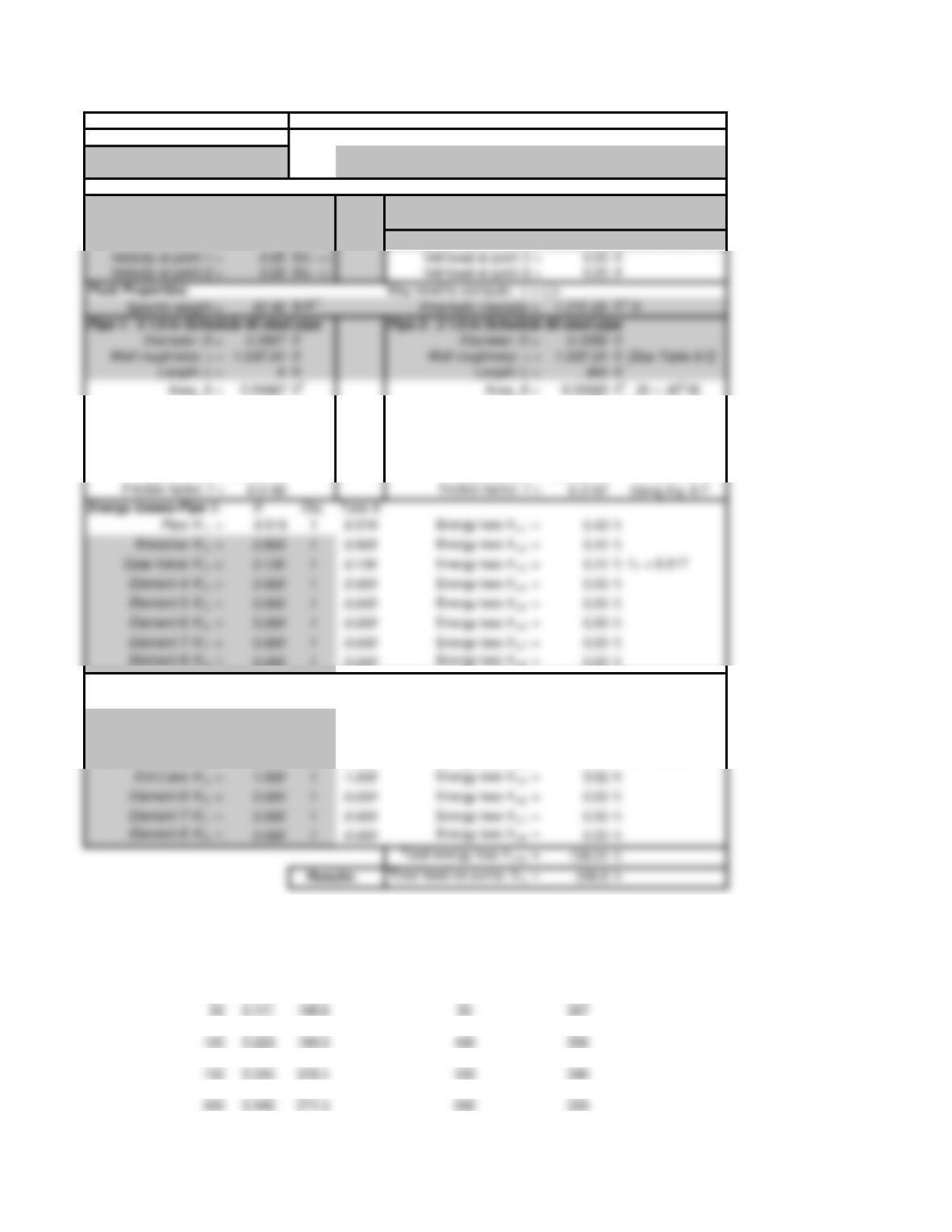
APPLIED FLUID MECHANICS System Curve US: CLASS I SERIES SYSTEMS
Objective: System Curve Reference points for the energy equation:
Ex. Problem 13.4 Pt. 1: Surface of lower reservoir
Fig. 13.41 Pt. 2: Surface of upper reservoir
System Data: U.S. Customary Units
Volume flow rate: Q = 0.5011
ft 3/s Elevation at point 1 = 0 ft
Pressure at point 1 = 0 psig Elevation at point 2 = 80 ft
Pressure at point 2 = 35 psig
If Ref. pt. is in pipe: Set v 1 “= B20” OR Set v2 “= E20“
D/e = 1971 D/e = 1372 Rel. roughness
L/D = 27 L/D = 1749
Flow Velocity = 7.30 ft/s Flow Velocity = 15.06
ft/s [v = Q/A ]
Velocity head = 0.827 ft Velocity head = 3.524
ft [v2/2g ]
Reynolds No. = 1.78E+05 Reynolds No. = 2.56E+05
[NR = vD/ n]
Energy losses-Pipe 1: KQty. Total K
Pipe: K1 = 0.519 1 0.519 Energy loss hL1 = 0.43 ft
Energy losses-Pipe 2: KQty. Total K
Pipe: K1 = 34.488 1 34.488 Energy loss hL1 = 121.53 ft
Check Valve: K2 = 1.800 1 1.800 Energy loss hL2 = 6.34 ft fT = 0.018
Butterfly Valve: K 3 = 0.810 1 0.810 Energy loss hL3 = 2.85 ft fT = 0.018
Standard Elbow: K4 = 0.540 2 1.080 Energy loss hL4 = 3.81 ft fT = 0.018
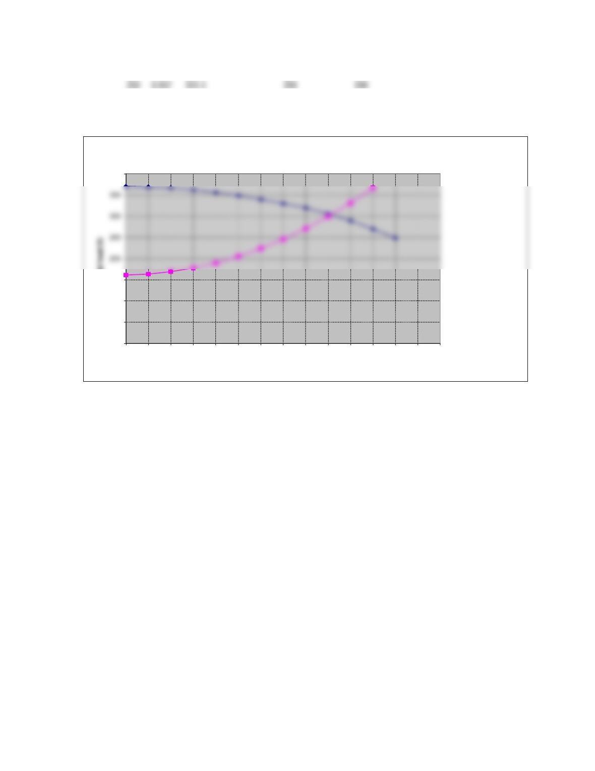
Figure 13.34 Total head on the pump at the desired operating point for Example Problem 13.1
SYSTEM CURVE PUMP CURVE: 2X3-10 PUMP WITH 9-IN IMPELLER
Q (gpm) Q (cfs) ha (ft) Q (gpm) Total head (ft)
0 0 160.8 0 370
25 0.056 162.9 25 369
75 0.167 177.6 75 362
125 0.278 205.4 125 349
175 0.390 246.1 175 330
Fluid Properties: May need to compute: n = h/r
Pipe 1: 3 1/2-in Schedule 40 steel pipe Pipe 2: 2 1/2-in Schedule 40 steel pipe
225 0.501 299.8 225 306
275 0.612 366.3 275 270
300 0.668 300 249
0
50
100
150
400
025 50 75 100 125 150 175 200 225 250 275 300
Total head (ft)
Capacity (gal/min)
Figure 13.36 Operating Point for Example Problem 13.1
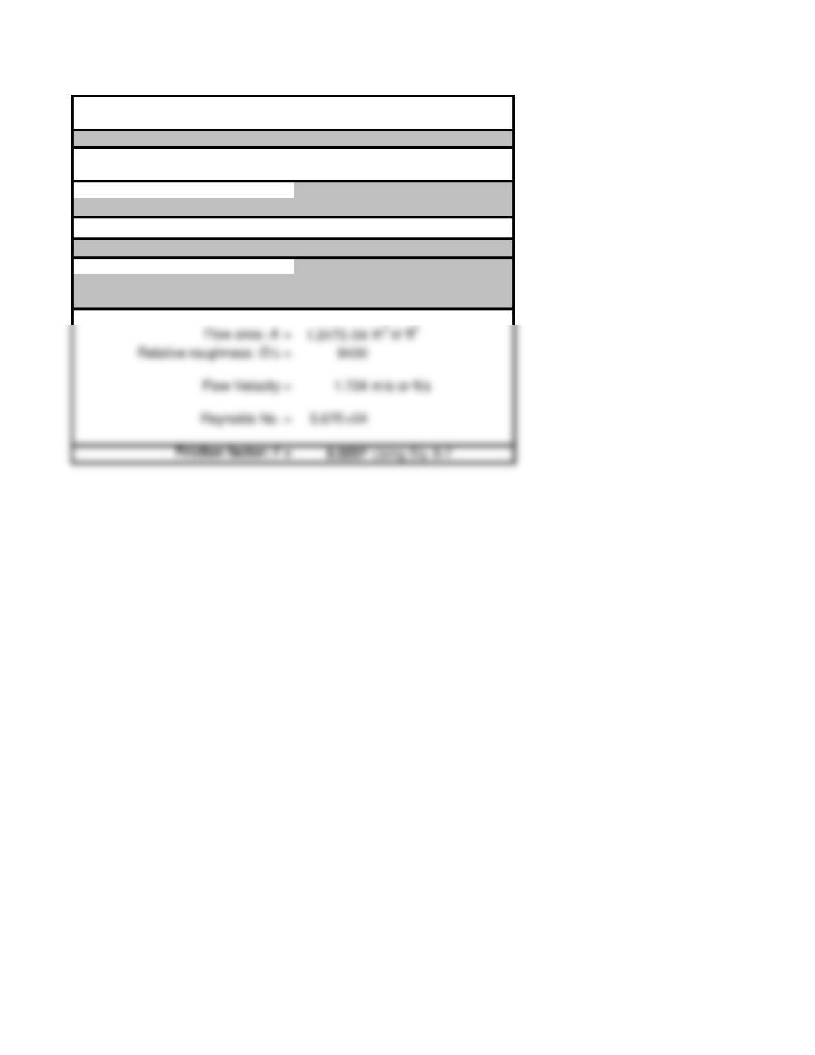
Friction Factor Calculation using Swamee-Jain Equation 8-7
Problem 8.28: Friction factor only; SI data
Use consistent SI or U.S. Customary units
Fluid Properties: Water at 75 deg C
Kinematic Viscosity 3.83E-07
m2/s or ft2/s
Volume flow rate: Q = 2.15E-04
m3/s or ft3/s
Pipe Data: 15 mm OD × 1.2 mm wall Copper
Pipe wall roughness: e = 1.50E-06 m or ft
Pipe diameter = 0.0126 m or ft
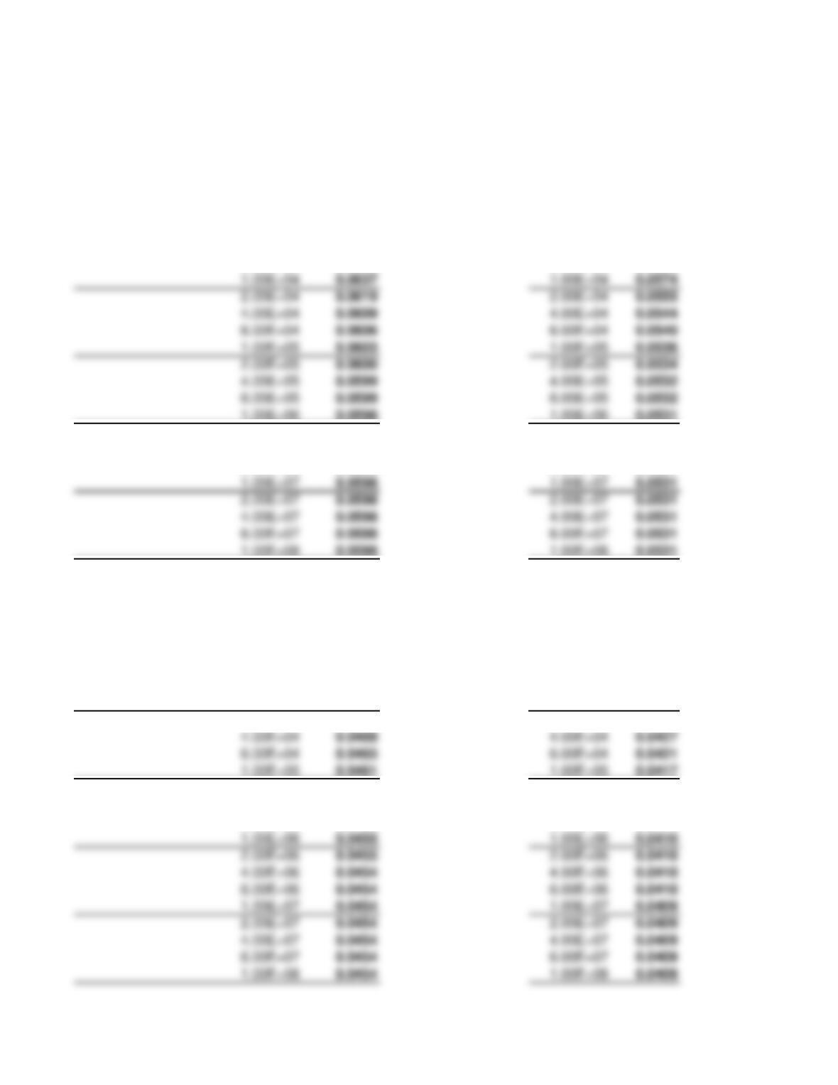
Data for friction factor curves
D/e30 D/e40
Friction factor Friction factor
Reynolds number f Reynolds number f
4.00E+03
0.0685 4.00E+03 0.0626
6.00E+03
0.0659 6.00E+03 0.0598
1.00E+06
0.0598 1.00E+06 0.0531
2.00E+06
0.0598 2.00E+06 0.0531
4.00E+06
0.0598 4.00E+06 0.0531
6.00E+06
0.0598 6.00E+06 0.0531
0.0598 1.00E+07 0.0531
0.0598 2.00E+07 0.0531
0.0598 4.00E+07 0.0531
0.0598 6.00E+07 0.0531
0.0598 1.00E+08 0.0531
D/e60 D/e80
Friction factor Friction factor
Reynolds number f Reynolds number f
4.00E+03
0.0562 4.00E+03 0.0528
6.00E+03
0.0532 6.00E+03 0.0495
1.00E+04
0.0505 1.00E+04 0.0466
2.00E+04
0.0482 2.00E+04 0.0441
0.0469 4.00E+04 0.0427
0.0465 6.00E+04 0.0421
0.0461 1.00E+05 0.0417
2.00E+05
0.0458 2.00E+05 0.0413
4.00E+05
0.0456 4.00E+05 0.0412
6.00E+05
0.0455 6.00E+05 0.0411
0.0455 1.00E+06 0.0410
0.0455 2.00E+06 0.0410
0.0454 4.00E+06 0.0410
0.0454 6.00E+06 0.0410
0.0454 1.00E+07 0.0409
0.0454 2.00E+07 0.0409
0.0454 6.00E+07 0.0409
0.0454 1.00E+08 0.0409
0.0637 1.00E+04 0.0574
0.0619 2.00E+04 0.0555
0.0609 4.00E+04 0.0544
0.0606 6.00E+04 0.0540
0.0603 1.00E+05 0.0536
0.0600 2.00E+05 0.0534
0.0599 4.00E+05 0.0532
0.0599 6.00E+05 0.0532