Chapter 11
186
Prac
t
i
c
e
pro
b
l
e
ms
for
any
cla
s
s
11.21 Class I Pt. 1 at tank surface, Pt. 2 in stream outside pipe: p1 = p2 = 0;
1 = 0
In Eq. I
2
11.22 Class I Pt. 1 at collector tank surface. Pt. 2 at pump inlet. p1 = 0,
1 = 0
22
1 1 2 2
21
:
2 2
L
p p
z h z
g g
2
2
2 1 2
( ) 2
L
p z z h g
I
2 2 0.1723 ft 2 2 2
g g g g g
Entrance Filter Friction Valve
SERIES PIPE LINE SYSTEMS
187
SERIES PIPE LINE SYSTEMS
189
Chapter 11
190
SERIES PIPE LINE SYSTEMS
191
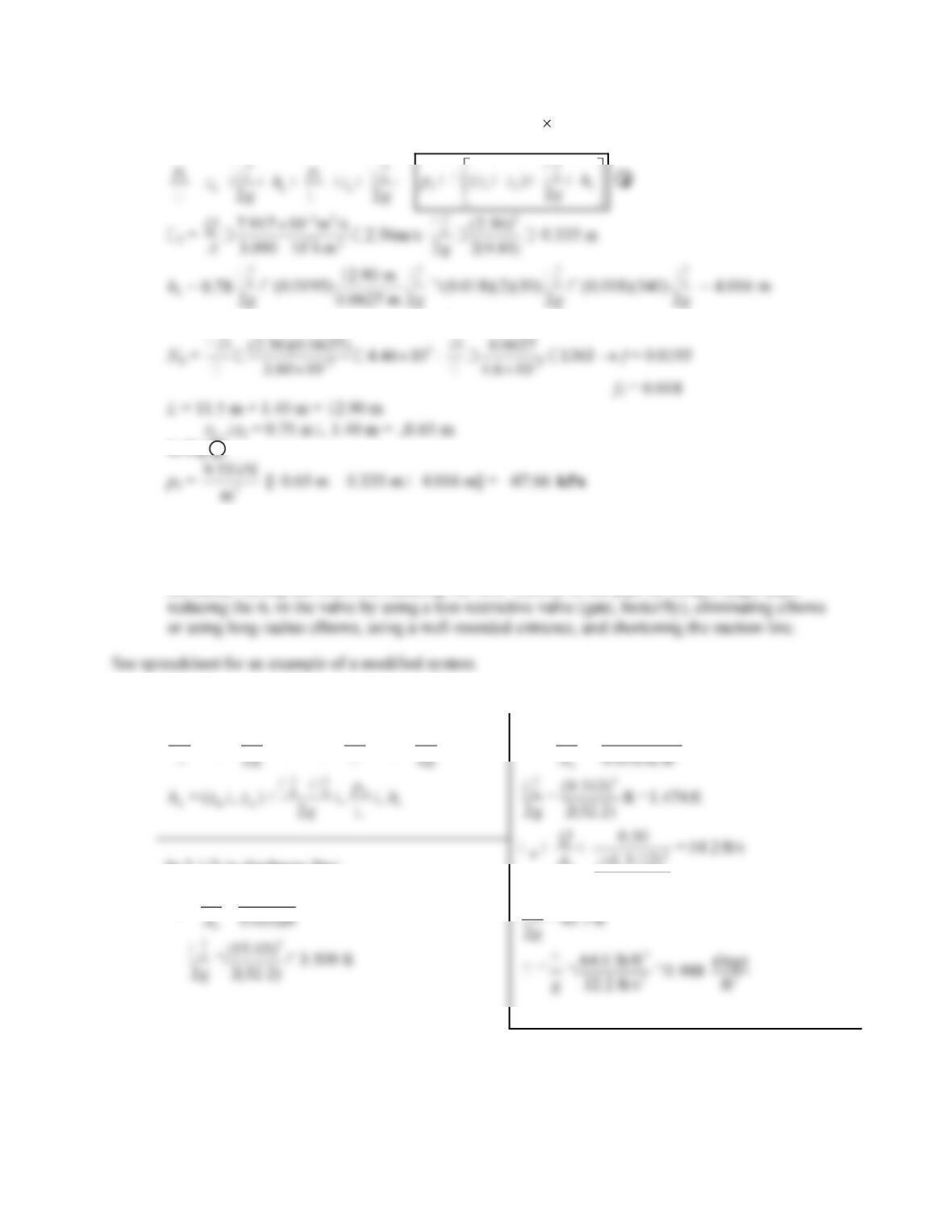
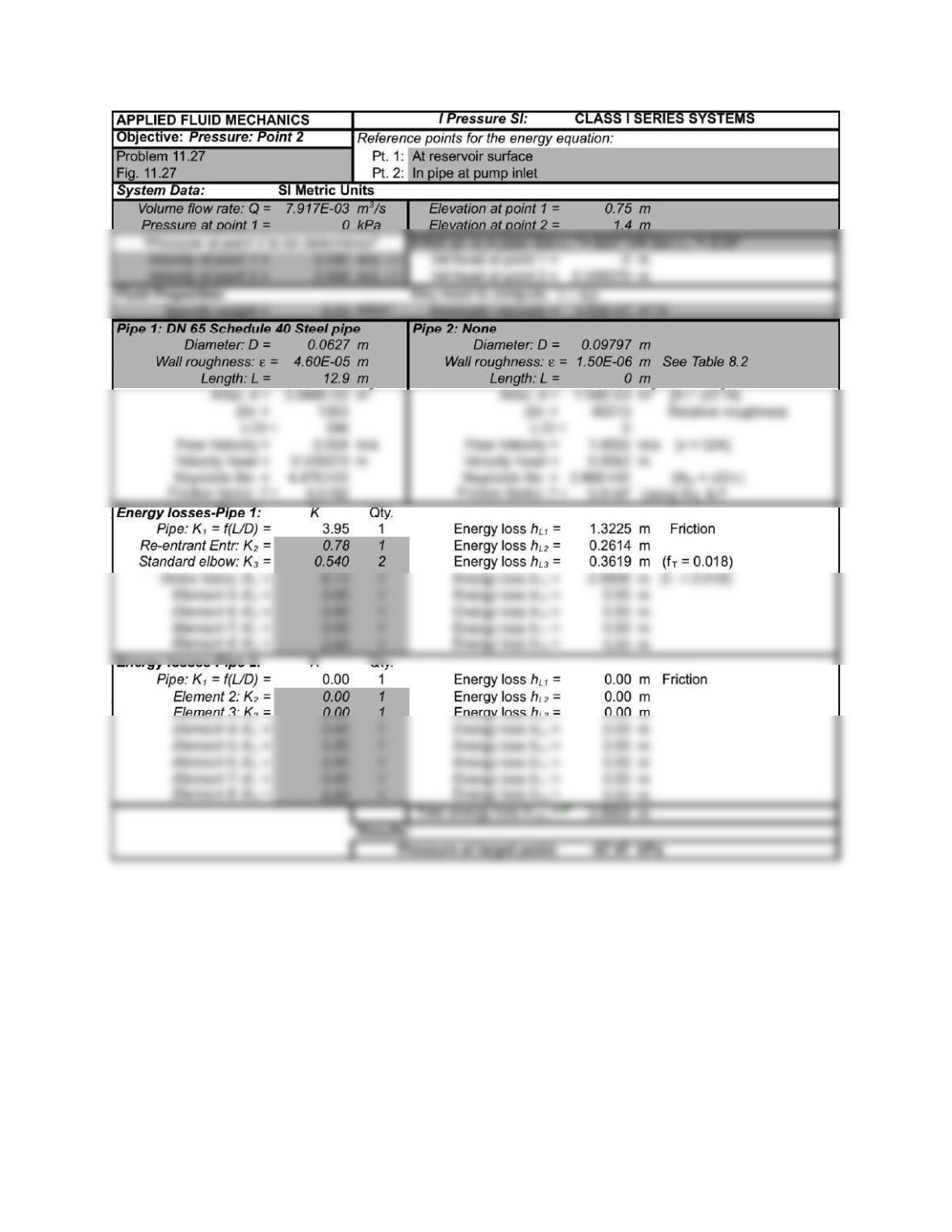
See also spreadsheet solution.
11.27 Class I Q = 475 L/min (1 m
3
/s/60000 L/min) = 7.917 10
–
3
m
3
/s
Pt. 1 at reservoir surface; Pt. 2 at pump inlet. p1 = 0,
1 = 0
Entrance Friction 2 Elbows Valve
In Eq. I
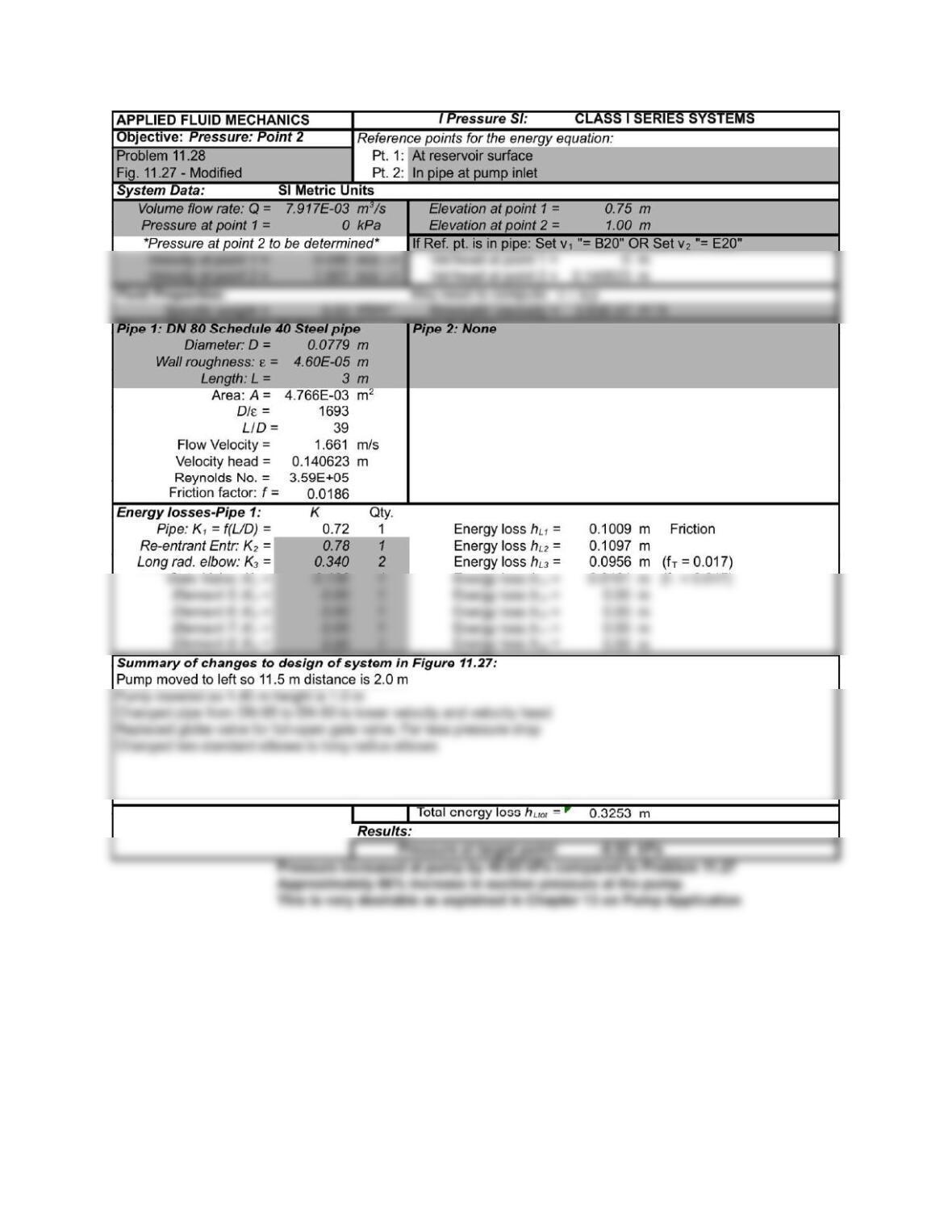
11.28 Design problem with variable solutions: Pressure at pump inlet can be increased by: lowering
the pump, raising the reservoir, reducing the flow velocity in the pipe by using a larger pipe,
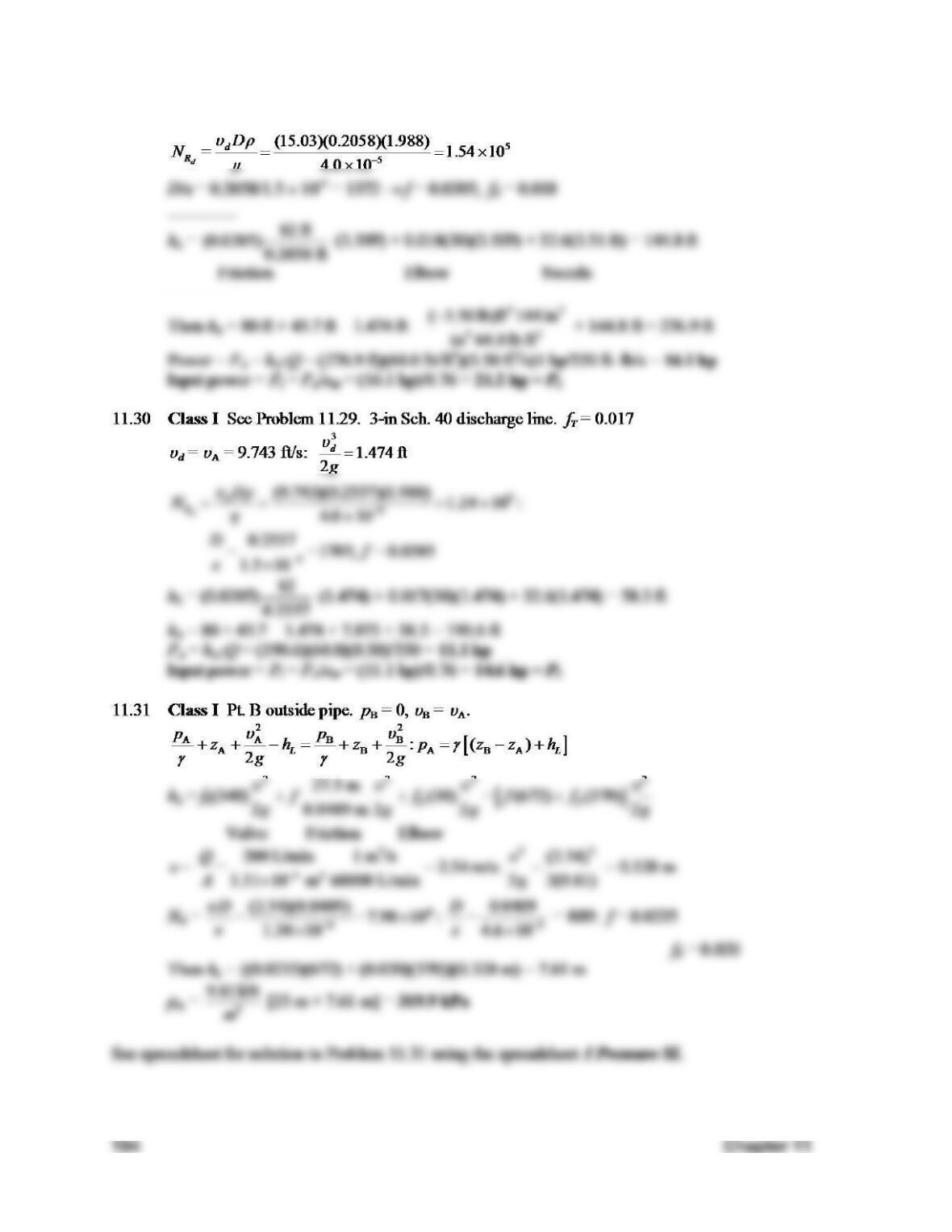
11.29 Class I Pt. B in stream outside nozzle. pB = 0
22
A A B B
A A B
L
p p
z h h z
In 2 1/2-in discharge line:
0.50 15.03 ft/s
d
Q
3
A2
2
B
0.50 ft /s
9.743 ft/s
(1.3/12)
4
B
Q
A
Chapter 11
192
SERIES PIPE LINE SYSTEMS
193
SERIES PIPE LINE SYSTEMS
195
Chapter 11
196
Prob
l
e
m
s
11.32
and
1
1.33
are
s
o
l
v
ed
u
s
in
g
the
sp
r
e
a
d
she
e
t
on
the
fo
l
l
ow
i
n
g
two
pa
g
es.
The
s
e
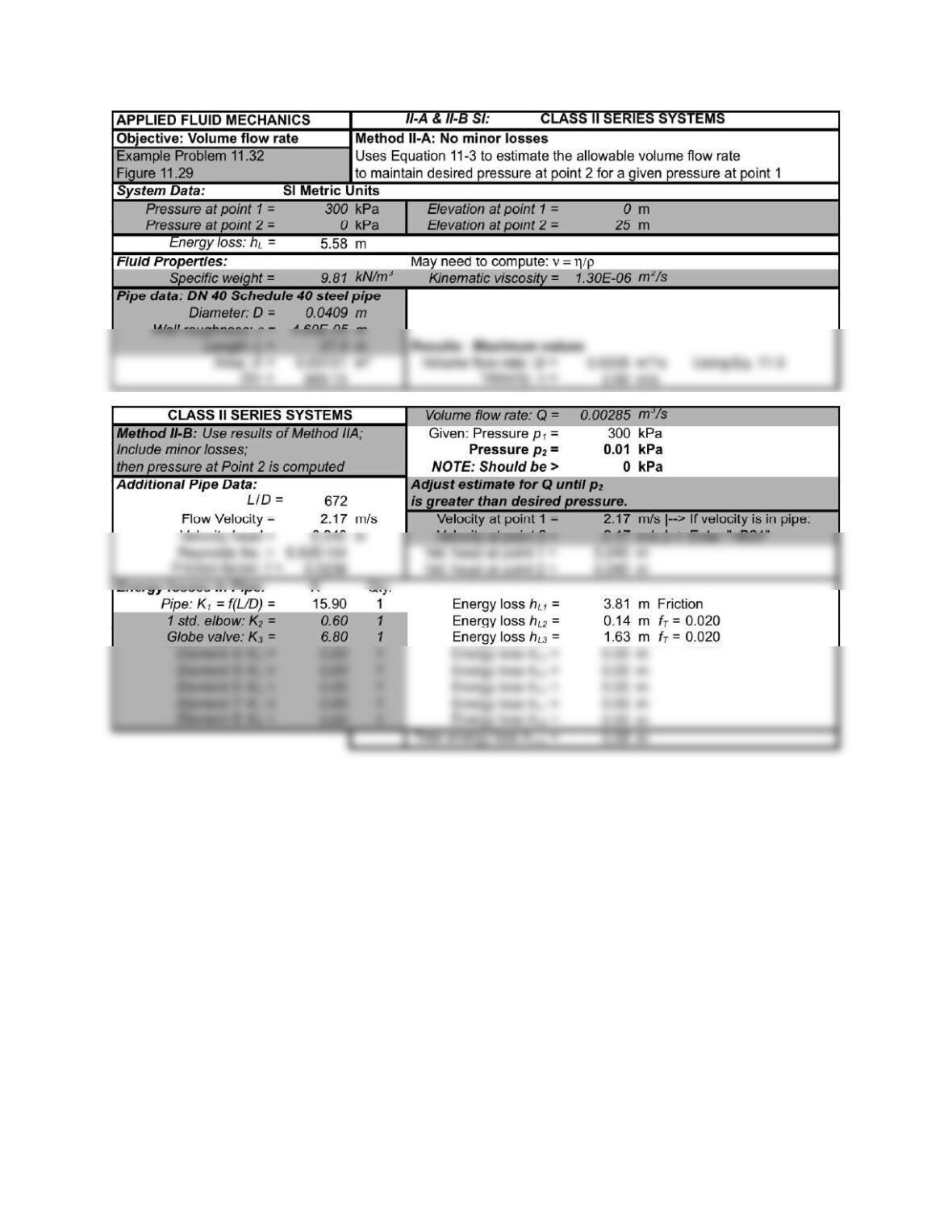
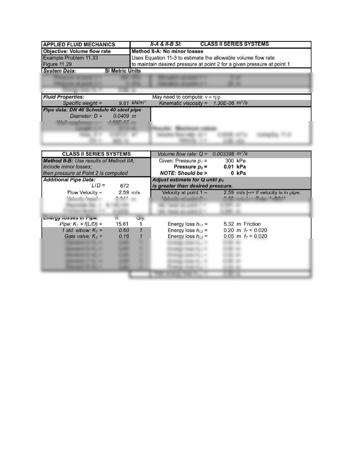
problems are of the Class II type and are solved using the procedure described in Section 11.4.
Method II-B is used because the system contains significant minor losses. In fact, one objective of
these two problems is to compare the performance of two design approaches for the same system,
using a different, more efficient valve in Problem 11.33 as compared with Problem 11.32.
Recall that Method II-A is set up and solved first in the spreadsheet. This ignores the minor losses and
gives an upper limit for the volume flow rate that can be delivered through the system with a given
d
SERIES PIPE LINE SYSTEMS
197
Chapter 11
198
SERIES PIPE LINE SYSTEMS
199
11.34
C
l
ass
I
Pt.
1
a
t
s
u
rf
a
ce
o
f
t
an
k
A;
Pt.
2
o
u
t
s
ide
pi
p
e
i
n
tan
k
B.
1
= 0
22
1 1 1 2
21
:
2 2
L
p p
z h z
g g
2
2
1 2 2 1
( ) 2L
p = p + z z h
g
I
2 =
223
2
2
250 gal/min 1 ft /s (23.87)
= 23.87 ft/s: = = 8.844 ft
0.02333 ft 449 gal/min 2g 2(32.2)
Q =
A
SERIES PIPE LINE SYSTEMS
201