PROBLEM 11.13
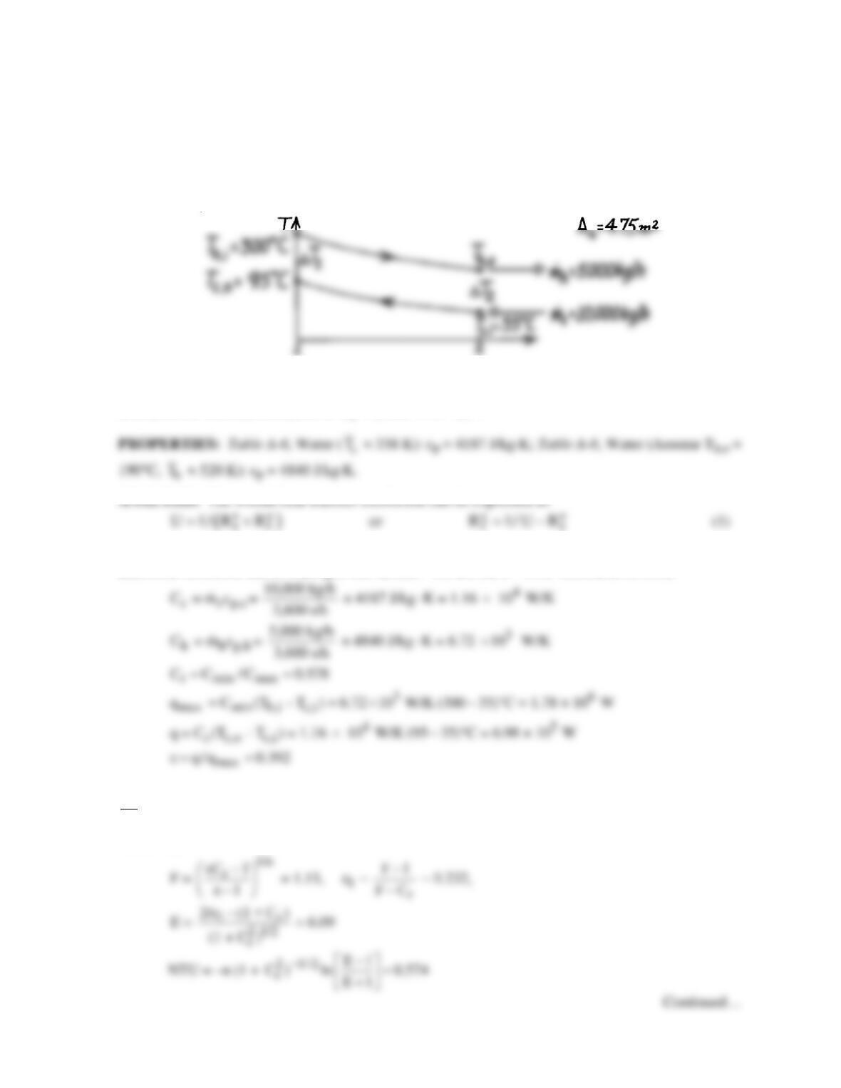
KNOWN: The shell and tube Hxer (two shells, four tube passes) of Problem 11.12, known to have
an area 4.75m2, provides 95°C water at the cold outlet (rather than 120°C) after several years of
operation. Flow rates and inlet temperatures of the fluids remain the same.
FIND: The fouling factor, Rf.
SCHEMATIC:
ASSUMPTIONS: (1) Negligible heat loss to surroundings, (2) Constant properties, (3) Thermal
resistance for the clean condition is
t
R′′ = (1500 W/m2⋅K)-1.
where
t
R′′
is the thermal resistance for the clean condition and
f
R′′
, the fouling factor, represents the
additional resistance due to fouling of the surface. We use the ε – NTU method as follows,
Note, that Th,o = Th,i – q/ Ch = 196°C, so properties should be evaluated at
h h,i h,o
T (T T ) / 2 248°C 521 K,=+==
very close to the assumed value. From Eqs. 11.31 and 11.30,
with n =2,
PROBLEM 11.13 (Cont.)
Thus,
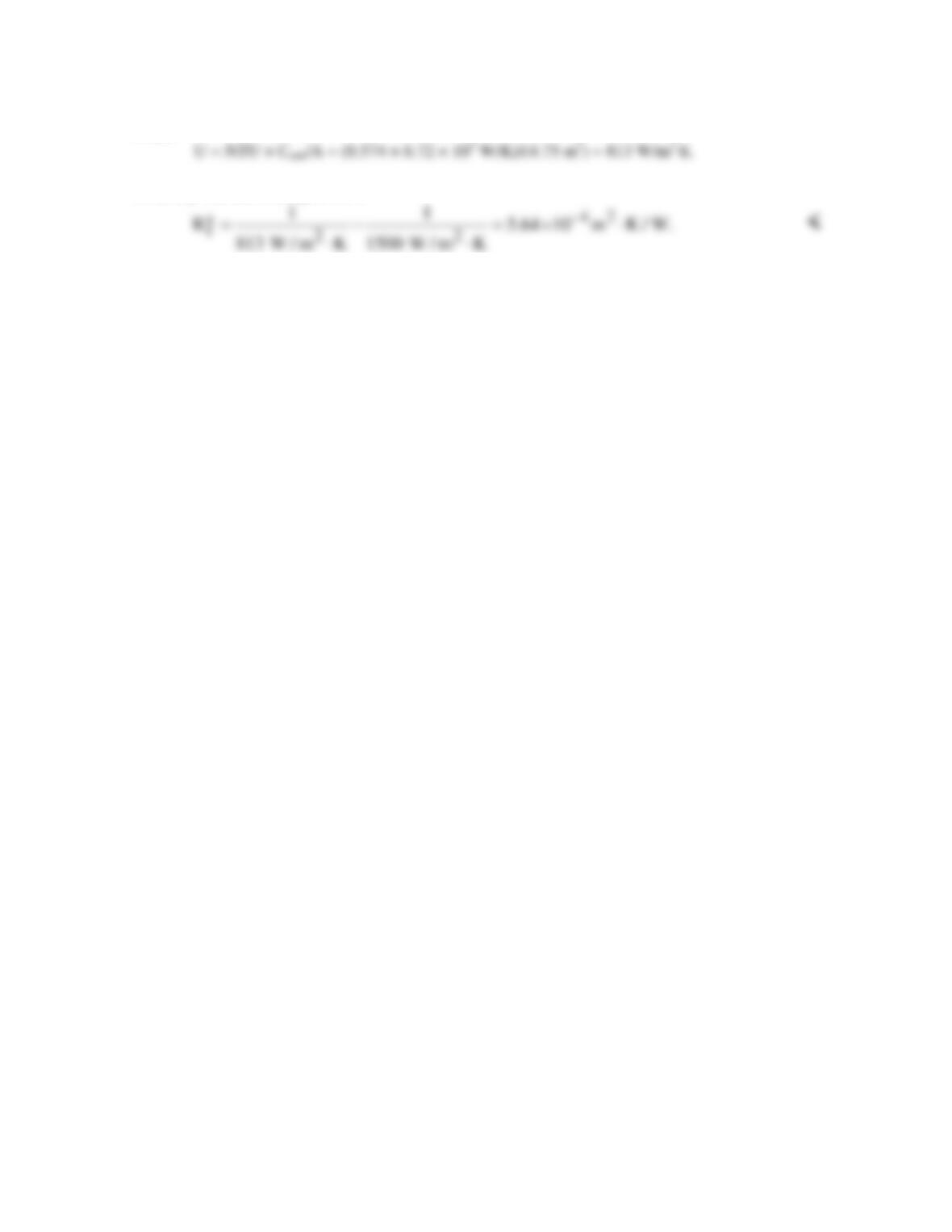
From Eq. (1), the fouling factor is
COMMENTS: Note that the effect of fouling is to nearly double (Uclean/Ufouled = 1500/813 ≈ 1.9)
the resistance to heat transfer. Note also the assumption for Th,o used for property evaluation is
satisfactory.
PROBLEM 11.14
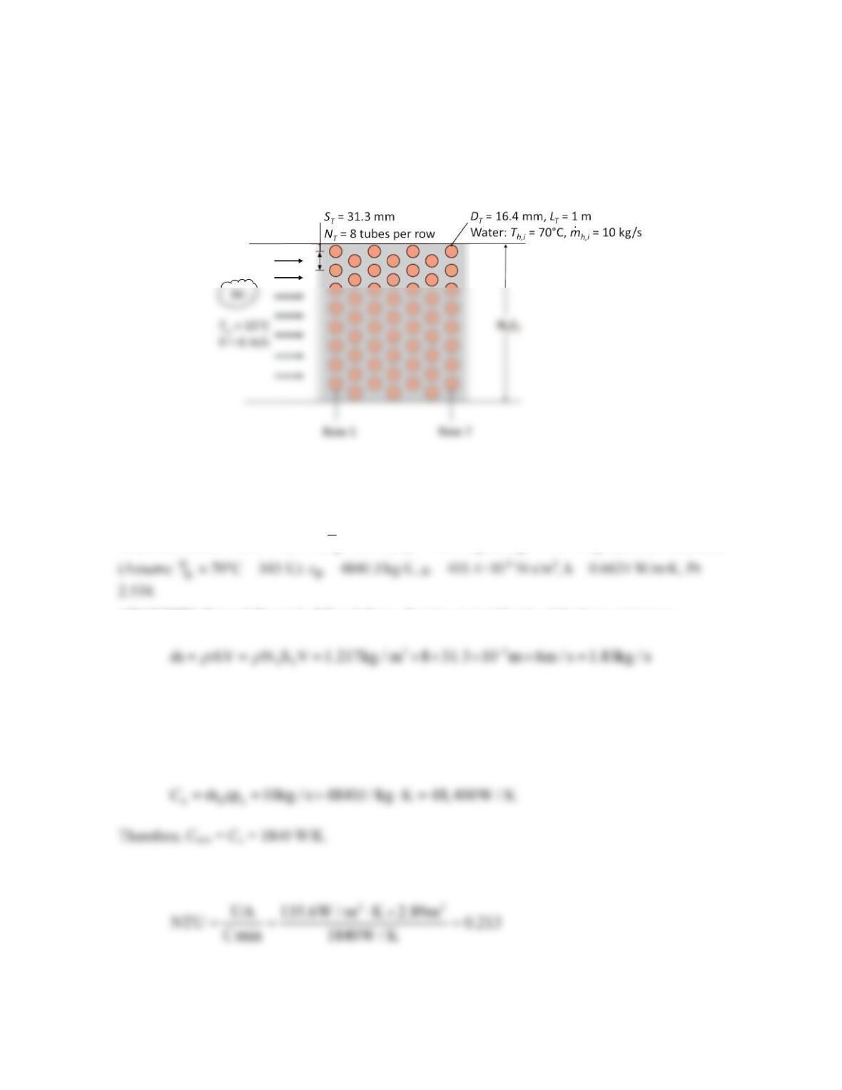
KNOWN: Geometry and operating conditions of tube bank of Example 7.7. Water flow rate. Air
side average heat transfer coefficient. Geometry of duct.
FIND: Heat rate using the ε–NTU method and overall heat transfer coefficient. Comment on the
validity of the assumption of isothermal tubes in Example 7.7.
SCHEMATIC:
ASSUMPTIONS: (1) Steady–state, incompressible flow conditions, (2) Negligible radiation effects,
(3) Constant properties, (4) Flow is uniformly distributed among tubes, (5) Fully-developed flow in
tubes.
PROPERTIES: Table A-4, Air (
c
T
≈ 288 K): ρ = 1.217 kg/m3, cp = 1007 J/kg⋅K; Table A-6, Water
ANALYSIS: Rework Example 7.7 as follows. For the air (cold) side of the heat exchanger,
so that
c cc
C m cp 1.83kg / s 1007J / kg K 1840W / K= = × ⋅=
For the water (hot) side of the heat exchanger,
The heat transfer surface area is A = NTNLπDL = 8×7×π×16.4×10-3m×1m= 2.89 m2, so that
Assuming the tubes surfaces remain at Tc,i = 70°C as in Example 7.7, Cmax →∞ and Cr = 0, Equation
(11.35a) yields
Continued…
PROBLEM 11.14 (Cont.)
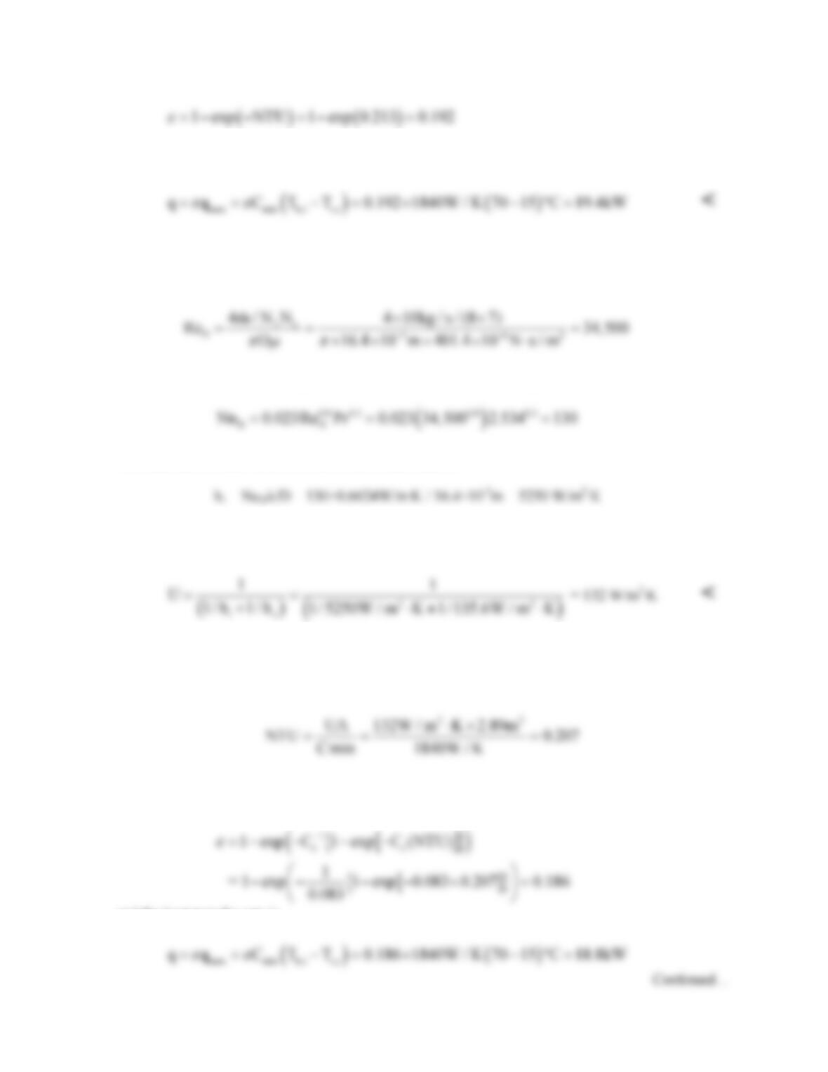
Therefore the heat rate is
The predicted heat rate using the ε–NTU method agrees with the heat rate determined in the example.
Now, consider the water flow in the tubes. The Reynolds number affiliated with each tube is
and the flow is turbulent. Using the Dittus-Boelter correlation of Chapter 8,
The heat transfer coefficient on the inside of each tube is
Therefore the overall heat transfer coefficient, accounting for the convection resistance of the internal
flow, is
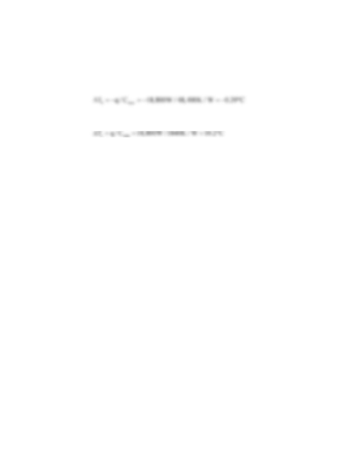
Relaxing the assumption of isothermal tubes in Example 7.7 Cr = Cmin/Cmax = 1840/48,400 = 0.083,
and
Since Cmin is associated with the mixed side of the crossflow heat exchanger, Equation (11.34a) may
be used to determine the effectiveness.
and the heat transfer rate is
PROBLEM 11.14 (Cont.)
The rate of heat transfer associated with the assumption of isothermal tube walls is (19.4 – 18.8)/18.8
× 100 = 3.2% higher than when the isothermal tube wall assumption is relaxed. The assumption of
isothermal tube walls is marginally valid. <
COMMENTS: (1) The temperature change in the water from tube inlet to tube outlet is
(2) The air temperature increases significantly as it progresses through the heat exchanger with
(3) The minimum tube wall temperature will exist at the end of the tubes in the first row of the heat
exchanger since this location corresponds to both minimum water and air temperatures.
PROBLEM 11.15
KNOWN: Inlet and outlet temperatures of hot and cold fluid streams in a concentric tube heat
exchanger.
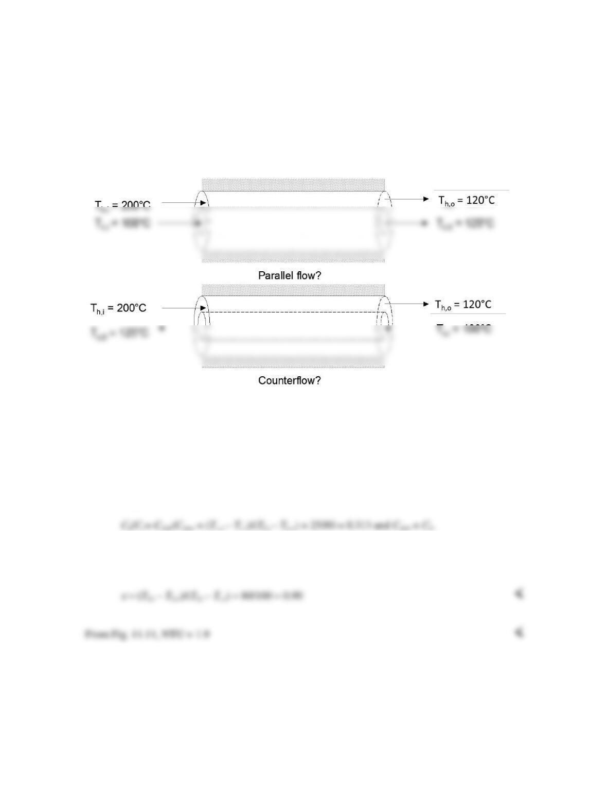
FIND: Whether the heat exchanger is operated in counter– or parallel flow, heat exchanger
effectiveness, heat exchanger NTU.
SCHEMATIC:
ASSUMPTIONS: (1) Negligible heat transfer between the heat exchanger and the surroundings, (2)
Constant properties.
ANALYSIS: The heat exchanger must be operating in a counterflow configuration because Th,o <
Tc,o. <
From energy balances on each fluid, q = Ch(Th,i – Th,o) = Cc(Tc,o – Tc,i), from which
From the definition of the effectiveness, q =
ε
Cmin(Th,i – Tc,i) =
ε
Ch(Th,i – Tc,i) = Ch(Th,i – Th,o) from
which
COMMENTS: The NTU may also be found from Eq. 11.29b, yielding NTU = 1.92.
PROBLEM 11.16
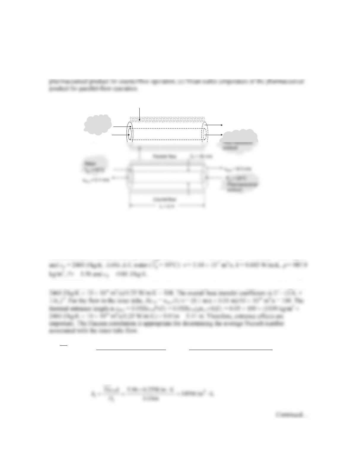
KNOWN: Inlet temperatures of pharmaceutical product and water in a concentric tube heat
exchanger. Tube diameters and fluid velocities.
FIND: (a) Value of the overall heat transfer coefficient, U, (b) Mean outlet temperature of the
SCHEMATIC:
ASSUMPTIONS: (1) Negligible heat transfer between the heat exchanger and the surroundings, (2)
Constant properties, (3) Negligible conduction resistance posed by the thin-walled inner tube, (4)
Smooth tube surfaces.
PROPERTIES: Pharmaceutical product (given):
ν
= 10 × 10–6 m2/s, k = 0.25 W/m⋅K,
ρ
= 1100 kg/m3
ANALYSIS: (a) The Prandtl number of the pharmaceutical product is Prc =
ρ
cp
ν
/k = (1100 kg/m3 ×
( ) ( )
2/3 2/3
0.0668( / ) 0.0668 (0.01/ 2) 100 108
3.66 3.66 5.96
1 0.04 / 1 0.04 0.01/ 2 100 108
Di
Di
Di
D L Re Pr
Nu
D L Re Pr
× ××
=+=+ =
+ + ××
Therefore,
T
h,i
= 60°C
T
c,i
= 20°C
u
m,h
= 0.2 m/s
u
m,c
= 0.1 m/s
Water
D
o
= 20 mm
Problem 11.16 (Cont.)
For the annular flow, ReDh = um,h(Do – Di)/
ν
= 0.2 m/s × 0.01 m/5.54 × 10-7 m2/s = 3610. Hence, the
Gnielinski correlation is appropriate for use. The friction factor for the annular region is obtained from
Eq. 8.21 and is
Therefore,
and
The overall heat transfer coefficient is
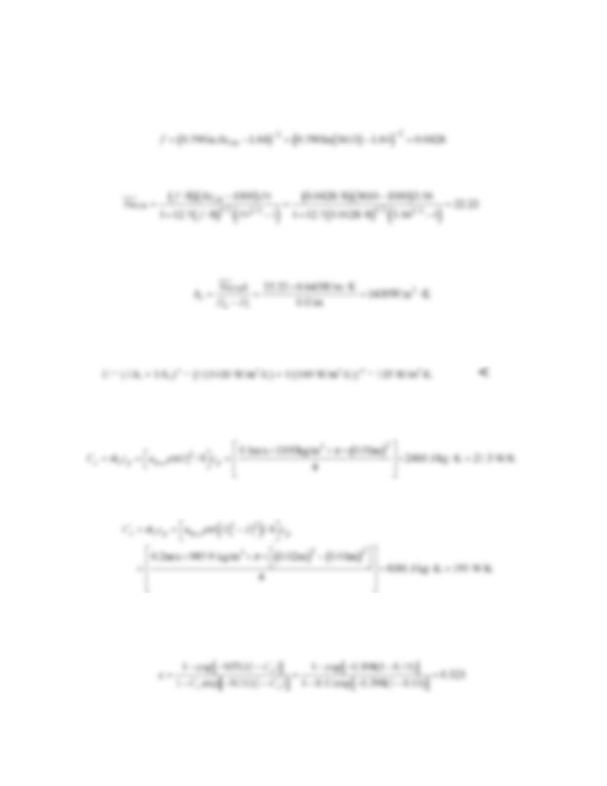
(b) The heat capacity rate of the cold (pharmaceutical product) stream is
The heat capacity rate of the hot (water) stream is
Therefore, Cr = Cmin/Cmax = (21.3 W/K)/(195 W/K) = 0.11 and the number of transfer units is NTU =
UA/Cmin = U
π
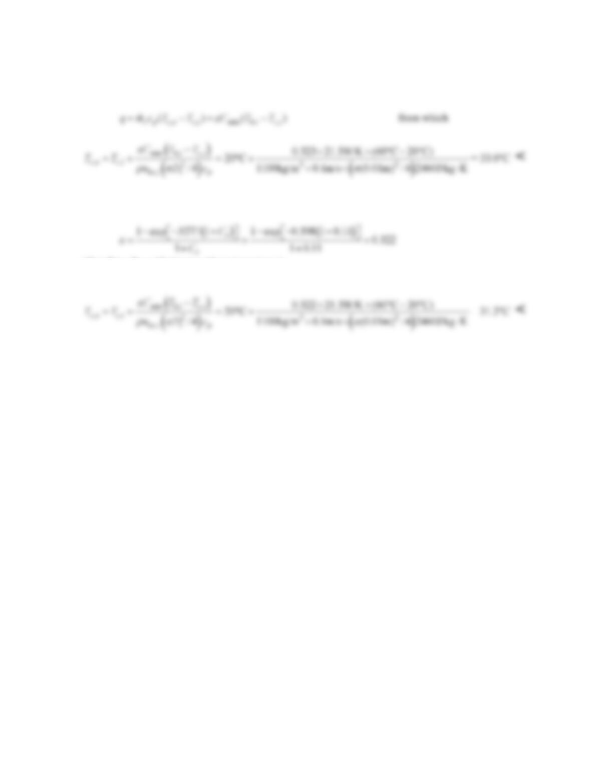
DiL/Cmin = (135 W/m2⋅K × π × 0.01 m × 2m)/21.3 W/K = 0.398. The effectiveness of
the counterflow heat exchanger is obtained from Eq. 11.29a and is
Continued…
Problem 11.16 (Cont.)
The heat transfer rate is
(c) For parallel–flow operation,
Therefore, the cold stream outlet temperature is
COMMENTS: There is little difference in the outlet temperature of the pharmaceutical product.
However, if the outlet temperature of the pharmaceutical product cannot exceed some critical value,
the heat exchanger should be operated in parallel–flow since the ultimate outlet temperature associated
with a very long concentric tube apparatus would be determined by the conservation of energy
principle.
PROBLEM 11.17
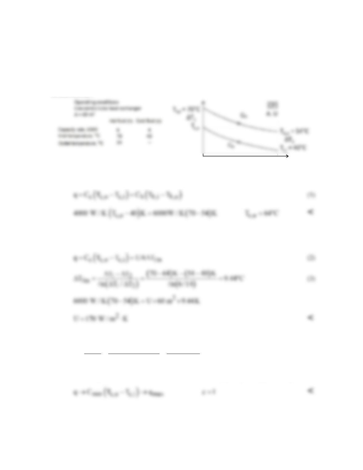
KNOWN: Concentric tube heat exchanger with area of 60 m2 with operating conditions as shown on
the schematic.
FIND: (a) Outlet temperature of the hot fluid; (b) Whether the exchanger is operating in counterflow
or parallel flow; or can’t tell from information provided; (c) Overall heat transfer coefficient; (d)
Effectiveness of the exchanger; and (e) Effectiveness of the exchanger if its length is made very long.
SCHEMATIC:
ASSUMPTIONS: (1) Negligible heat loss to surroundings, (2) Constant properties.
ANALYSIS: From overall energy balances on the hot and cold fluids, find the hot fluid outlet
temperature
(b) HXer must be operating in counterflow (CF) since Th,o < Tc,o.
(c) From the rate equation with A = 60 m2, with Eq. (1) for q,
(d) The effectiveness, from Eq. 11.19, with the cold fluid as the minimum fluid, Cc = Cmin ,
( )
( )
( )
( )
c c,o c,i
max min h,i c,i
CT T 64 40 K
q0.8
q 70 40 K
C TT
ε
−−
= = = =
−
−
<
(e) For a very long CF HXer, the outlet of the minimum fluid, Cmin = Cc, will approach Th,i. That is,
PROBLEM 11.18
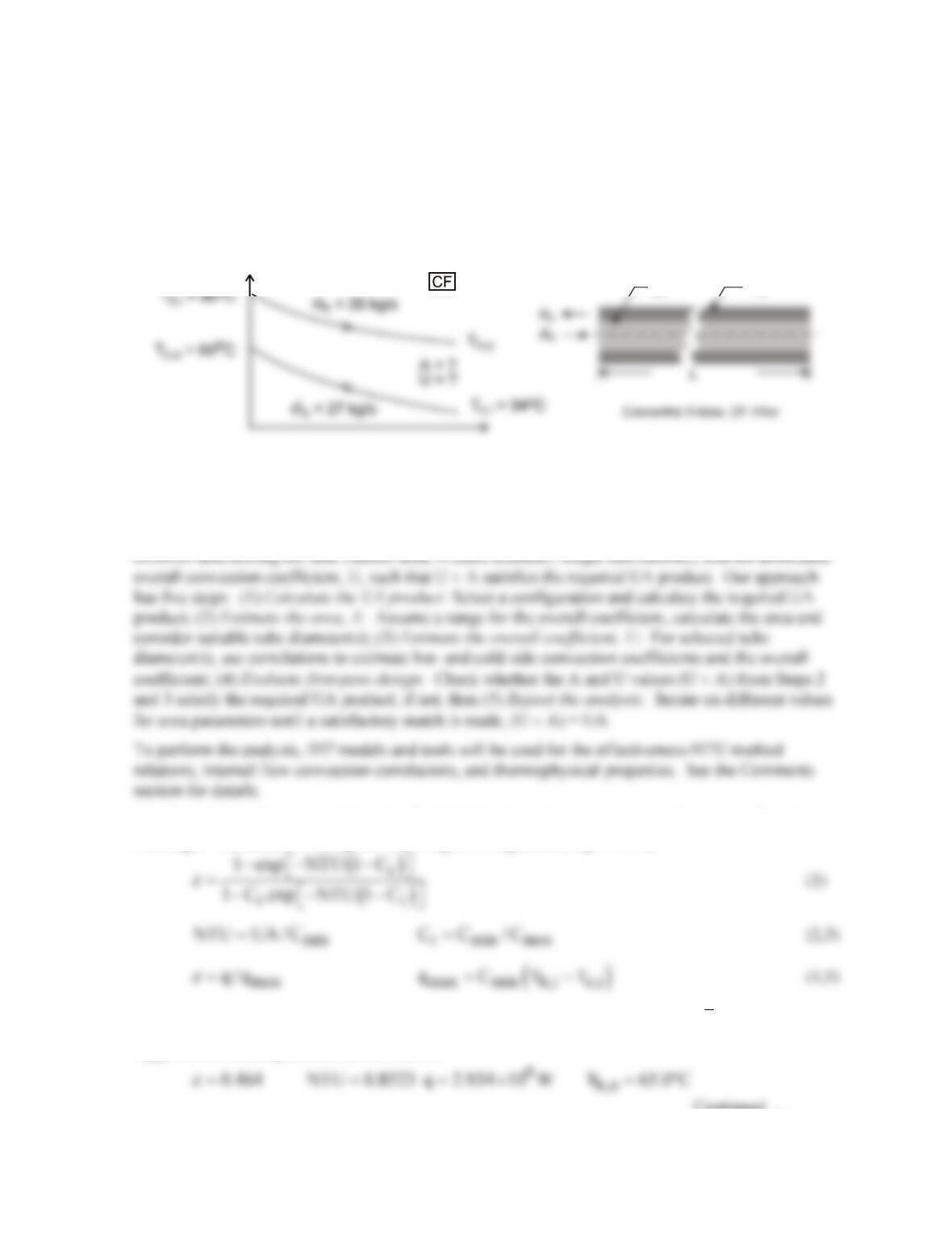
KNOWN: Specifications for a water–to–water heat exchanger as shown in the schematic including
the flow rate, and inlet and outlet temperatures.
FIND: (a) Design a heat exchanger to meet the specifications; that is, size the heat exchanger, and (b)
Evaluate your design by identifying what features and configurations could be explored with your
customer in order to develop more complete, detailed specifications.
SCHEMATIC:
D
o
D
i
ASSUMPTIONS: (1) Negligible heat loss to surroundings, (2) Tube walls have negligible thermal
resistance, (3) Flow is fully developed, and (4) Constant properties.
ANALYSIS: (a) Referring to the schematic above and using the rate equation, we can determine the
value of the UA product required to satisfy the design requirements. Sizing the heat exchanger
Step 1 Calculate the required UA. For the initial design, select a concentric tube, counterflow heat
exchanger. Calculate UA using the following set of equations, Eqs. 11.29a,
where
p
C mc ,=
and cp is evaluated at the average mean temperature of the fluid,
m
T
= (Tm,i +
Tm,o)/2. Substituting numerical values, find
Continued …
PROBLEM 11.18 (Cont.)
4
UA 9.62 10 W / K= ×
<
Step 2 Estimate the area, A. From Table 11.2, the typical range of U for water–to–water exchangers is
850 – 1700 W/m2⋅K. With UA = 9.619 × 10⁴ W/K, the range for A is 57 – 113 m2, where
i
A D LN
π
=
(6)
where L and N are the length and number of tubes, respectively. Consider these values of Di with L =
10 m to describe the exchanger:
Step 3 Estimate the overall coefficient, U. With the inner (hot) and outer (cold) fluids in the
concentric tube arrangement, the overall coefficient is
io
1/ U 1/ h 1/ h= +
(7)
and the
h
are estimated using the Dittus-Boelter correlation assuming fully developed turbulent flow.
Coefficient, hot side,
i
h.
For flow in the inner tube,
and the correlation, Eq. 8.60 with n = 0.3, is
where properties are evaluated at the average mean temperature,
( )
h hi ho
T T T / 2.= +
Coefficient, cold side,
o
h.
For flow in the annular space, Do – Di, the above relations apply where
the characteristic dimension is the hydraulic diameter,
To determine the outer diameter Do, require that the inner and outer fluid flow areas are the same,
that is,
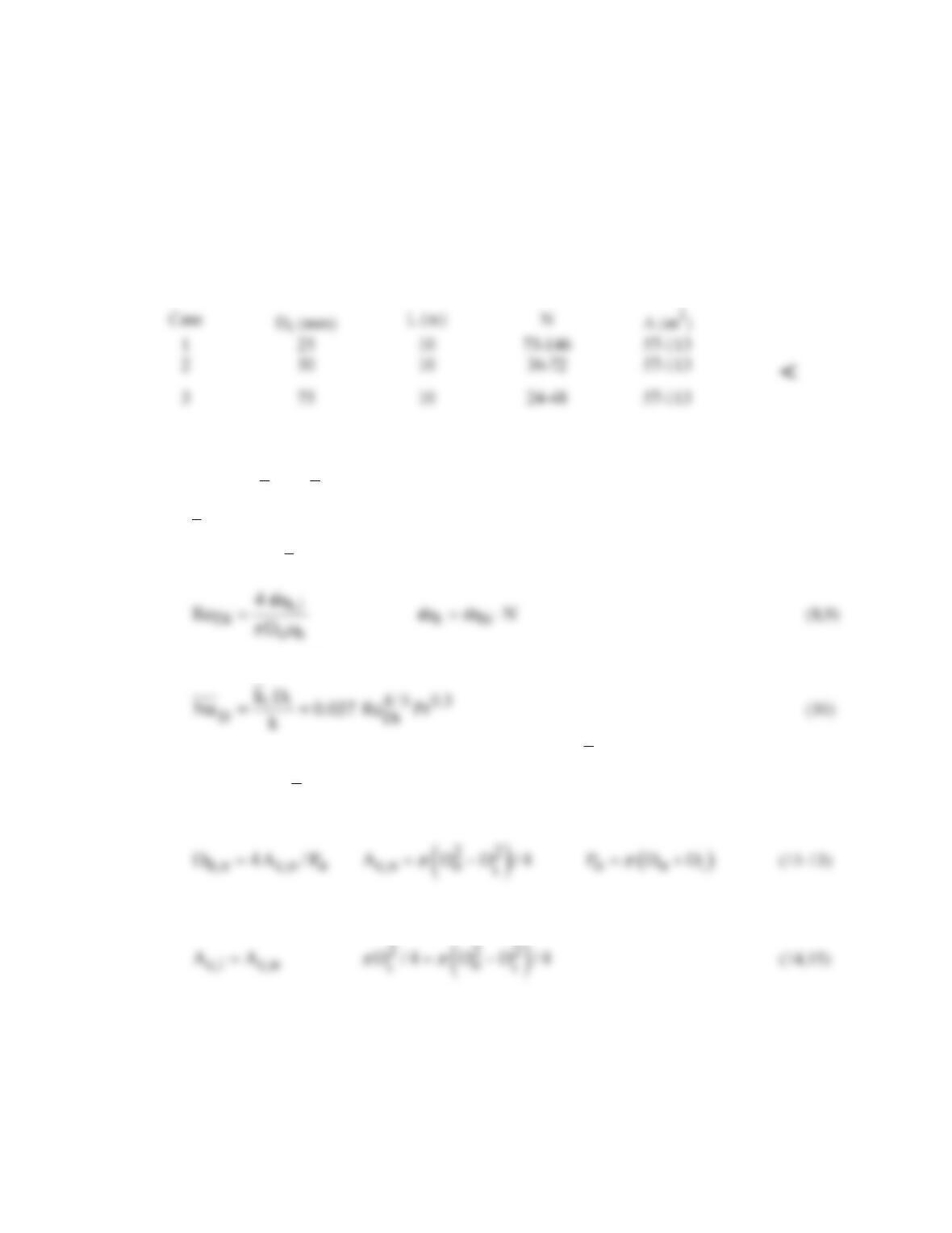
Summary of the convection coefficient calculations. The results of the analysis with L = 10 m are
summarized below.
Continued …
PROBLEM 11.18 (Cont.)
Case
D
i
N
A
i
h
o
h
U
U × A
(mm)
(m2)
(W/m2⋅K)
(W/m2⋅K)
(W/m2⋅K)
W/K
1a
25
73
57
4795
4877
2418
1.39
×
105
For all these cases, the Reynolds numbers are above 10,000 and turbulent flow occurs.
Step 4 Evaluate first-pass design. The required UA product value determined in step 1 is UA = 9.62
(b) What information could have been provided by the customer to simplify the analysis for design of
the exchanger? Looking back at the analysis, recognize that we had to assume the exchanger
configuration (type) and overall length. Will knowledge of the customer’s installation provide any
insight? While no consideration was given in our analysis to pumping power limitations, that would
affect the flow velocities, and hence selection of tube diameter.
COMMENTS: The IHT workspace with the relations for step 3 analysis is shown below, including
summary of key correlation parameters. The set of equations is quite stiff so that good initial guesses
are required to make the initial solve.
/* Results, Step 3 – Di = 25 mm, N = 73, L = 10 m
A Do U UA Di L N
57.33 0.03536 2418 1.386E5 0.025 10 73
ReDi ReDo hDi hDo
5.384E4 1.352E4 4795 4877 */
// Input variables
//Di = 0.050
Di = 0.025
//Di = 0.075
2a
50
36
57
2424
2465
1222
3a
75
24
57
1616
1644
PROBLEM 11.18 (Cont.)
// Flow rate and number of tubes, inside parameters (hot)
mdoth = N * umi * rhoi * Aci
Aci = pi * Di^2 /4
1 / U = 1 / hDi + 1/ hDo
UA = U * A
A = pi * Di * L * N
// Inside coefficient, hot fluid
NuDi = NuD_bar_IF_T_FD(ReDi,Pri,n) // Eq 8.60
// Outside coefficient, cold fluid
NuDo = NuD_bar_IF_T_FD(ReDo,Pro,nn) // Eq 8.60
// Water property functions :T dependence, From Table A.6
// Units: T(K), p(bars);
x = 0 // Quality (0=sat liquid or 1=sat vapor)
// Conversions
Thi_C = Thi – 273
Tho_C = Tho – 273
Tci_C = Tci – 273
Tco_C = Tco – 273
PROBLEM 11.19
KNOWN: Inlet and outlet temperatures for a shell-and-tube heat exchanger with 10 tubes
making eight passes. Heat transfer coefficient for oil flowing in shell. Mass flow rate of water in
tubes. Tube diameter.
FIND: Oil flow rate required to achieve specified outlet temperature. Tube length required to
achieve specified water heating.
SCHEMATIC:
.
ASSUMPTIONS: (1) Negligible heat loss to the surroundings, (2) Constant properties, (3)
Negligible tube wall thermal resistance and fouling effects, (4) Fully developed water flow in
tubes.
PROPERTIES: Table A.5, unused engine oil: (
h
T
= 130°C): cp = 2350 J/kg⋅K. Table A.6,
ANALYSIS: From the overall energy balance, Eq. 11.7b, the heat transfer required of the
exchanger is
PROBLEM 11.19 (Cont.)
Thus UA = NTU×Cmin = 10,420 W/K. To find the required tube length, we must know the heat
transfer coefficients for the water flow. We calculate the Reynolds number, with
1c
m m /N=
=
0.25 kg/s defined as the water flow rate per tube, Eq. 8.6 yields
Hence the flow is turbulent, and from Eq. 8.60,
and
COMMENTS: (1) With L/D = 1516, the assumption of fully developed conditions throughout
the tube is justified. (2) With eight passes, the shell length is approximately L/8 = 4.7 m.
PROBLEM 11.20
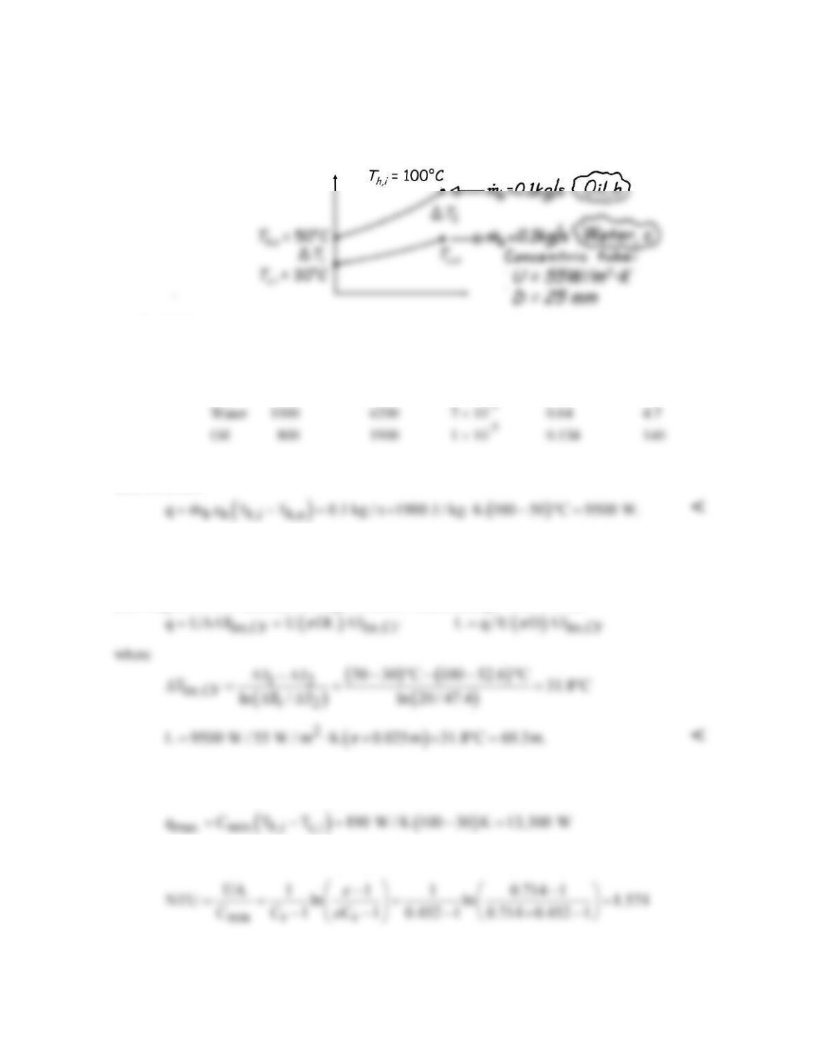
KNOWN: Counterflow concentric tube heat exchanger.
FIND: (a) Total heat transfer rate and outlet temperature of the water and (b) Required length.
SCHEMATIC:
ASSUMPTIONS: (1) Negligible heat loss to surroundings, (2) Negligible thermal resistance due to
tube wall thickness.
PROPERTIES: (given):
ρ (kg/m3) cp (J/kg⋅K) ν (m2/s) k (W/m⋅K) Pr
ANALYSIS: (a) With the outlet temperature, Tc,o = 50°C, from an overall energy balance on the hot
(oil) fluid, find
From an energy balance on the cold (water) fluid, find
c,o c,i c c
T T q / m c 30 C 9500 W / 0.1 kg / s 4200 J / kg K 52.6 C.= + = °+ × ⋅ = °
<
(b) Using the LMTD method, the length of the CF heat exchanger follows from
COMMENTS: Using the ε-NTU method, find Cmin = Ch = 190 W/K and Cmax = Cc = 420 W/K.
Hence
and ε=q/qmax = 0.714. With Cr = Cmin /Cmax = 0.452 and using Eq. 11.29b,
so that with A = 5.437m2 = πDL, find L = 69.3 m.
PROBLEM 11.21
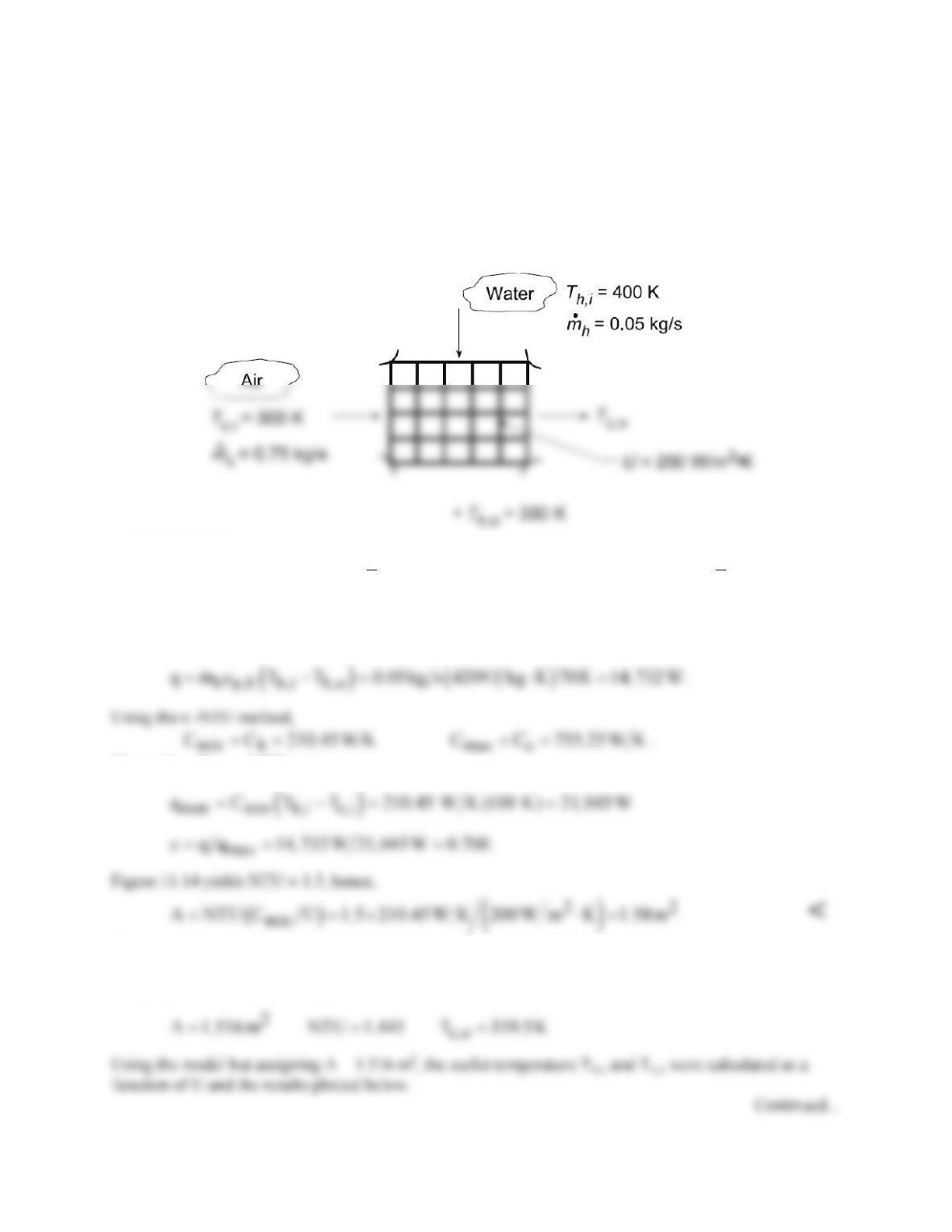
KNOWN: Flow rates and inlet temperatures for automobile radiator configured as a cross–flow heat
exchanger with both fluids unmixed. Overall heat transfer coefficient.
FIND: (a) Area required to achieve hot fluid (water) outlet temperature, Tm,o = 330 K, and (b) Outlet
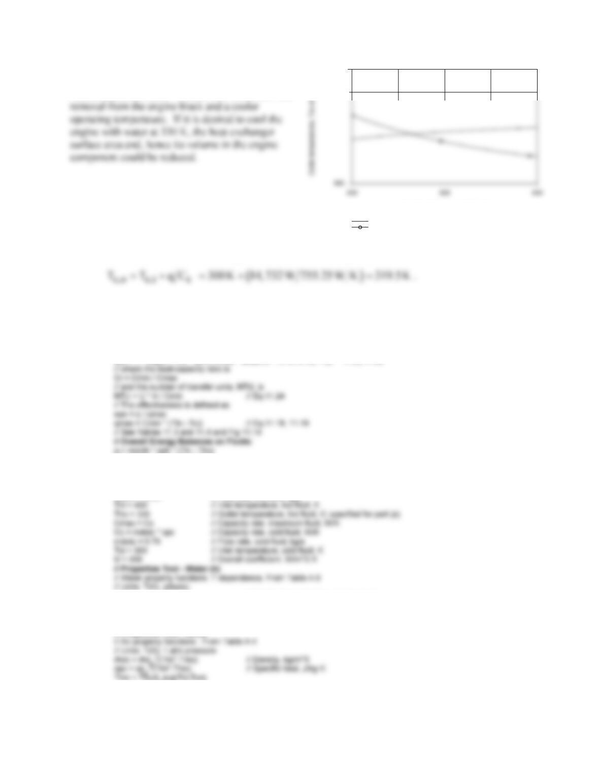
temperatures, Th,o and Tc,o, as a function of the overall coefficient for the range, 200 ≤ U ≤ 400 W/m2⋅K
with the surface area A found in part (a) with all other heat transfer conditions remaining the same as for
part (a).
SCHEMATIC:
ASSUMPTIONS: (1) Negligible heat loss to surroundings, (2) Constant properties.
PROPERTIES: Table A.6, Water (
h
T
= 365 K): cp,h = 4209 J/kg⋅K; Table A.4, Air
( )
c
T 310 K≈
: cp,c
= 1007 J/kg⋅K.
ANALYSIS: (a) The required heat transfer rate is
Hence, Cmin/Cmax = 0.279 and
(b) Using the IHT Heat Exchanger Tool for Cross-flow with both fluids unmixed arrangement and the
Properties Tool for Air and Water, a model was generated to solve part (a) evaluating the efficiency
using Eq. 11.32. The following results were obtained:
PROBLEM 11.21 (Cont.)
With a higher U, the outlet temperature of the hot
fluid (water) decreases. A benefit is enhanced heat
Overall coefficient, U (W/^2.K)
350
Cold fluid (air), Tco (K)
Hot fluid (water), Tho (K)
COMMENTS: (1) For the results of part (a), the air outlet temperature is
(2) The IHT workspace with the model to generate the above plot is shown below. Note that it is
necessary to enter the overall energy balances on the fluids from the keyboard.
// Heat Exchanger Tool – Cross–flow with both fluids unmixed:
// For the cross–flow, single–pass heat exchanger with both fluids unmixed,
eps = 1 – exp((1 / Cr) * (NTU^0.22) * (exp(–Cr * NTU^0.78) – 1)) // Eq 11.32
q = mdotc * cpc * (Tco – Tci)
// Assigned Variables:
Cmin = Ch // Capacity rate, minimum fluid, W/K
Ch = mdoth * cph // Capacity rate, hot fluid, W/K
mdoth = 0.05 // Flow rate, hot fluid, kg/s
xh = 0 // Quality (0=sat liquid or 1=sat vapor)
rhoh = rho_Tx(“Water”,Tmh,xh) // Density, kg/m^3
cph = cp_Tx(“Water”,Tmh,xh) // Specific heat, J/kg·K
Tmh = Tfluid_avg(Thi,Tho )
// Properties Tool – Air(c)
PROBLEM 11.22
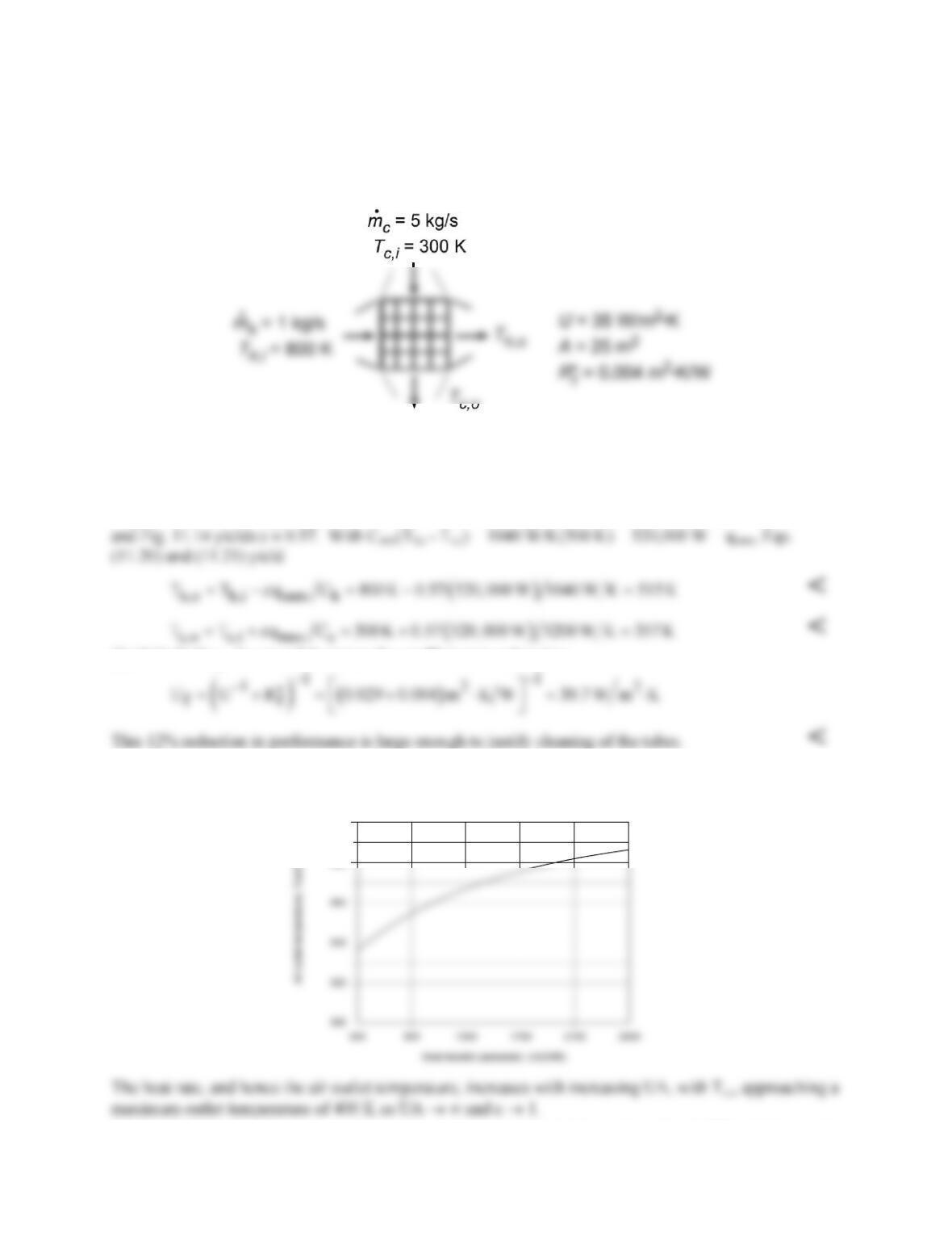
KNOWN: Flowrates and inlet temperatures of a cross–flow heat exchanger with both fluids unmixed.
Total surface area and overall heat transfer coefficient for clean surfaces. Fouling resistance associated
with extended operation.
FIND: (a) Fluid outlet temperatures, (b) Effect of fouling, (c) Effect of UA on air outlet temperature.
SCHEMATIC:
ASSUMPTIONS: (1) Negligible heat loss to surroundings, (2) Constant properties, (3) Negligible tube
wall resistance.
PROPERTIES: Air and gas (given): cp = 1040 J/kg⋅K.
ANALYSIS: (a) With Cmin = Ch = 1 kg/s × 1040 J/kg⋅K = 1040 W/K and Cmax = Cc = 5 kg/s × 1040
J/kg⋅K = 5200 W/K, Cmin/Cmax = 0.2. Hence, NTU = UA/Cmin = 35 W/m2⋅K(25 m2)/1040 W/K = 0.841
(b) With fouling, the overall heat transfer coefficient is reduced to
(c) Using the Heat Exchangers option from the IHT Toolpad to explore the effect of UA, we obtain the
following result.
380
400
COMMENTS: Note that, for conditions of part (a), Eq. 11.32 yields a value of ε = 0.538, which reveals
the level of approximation associated with reading ε from Fig. 11.14.