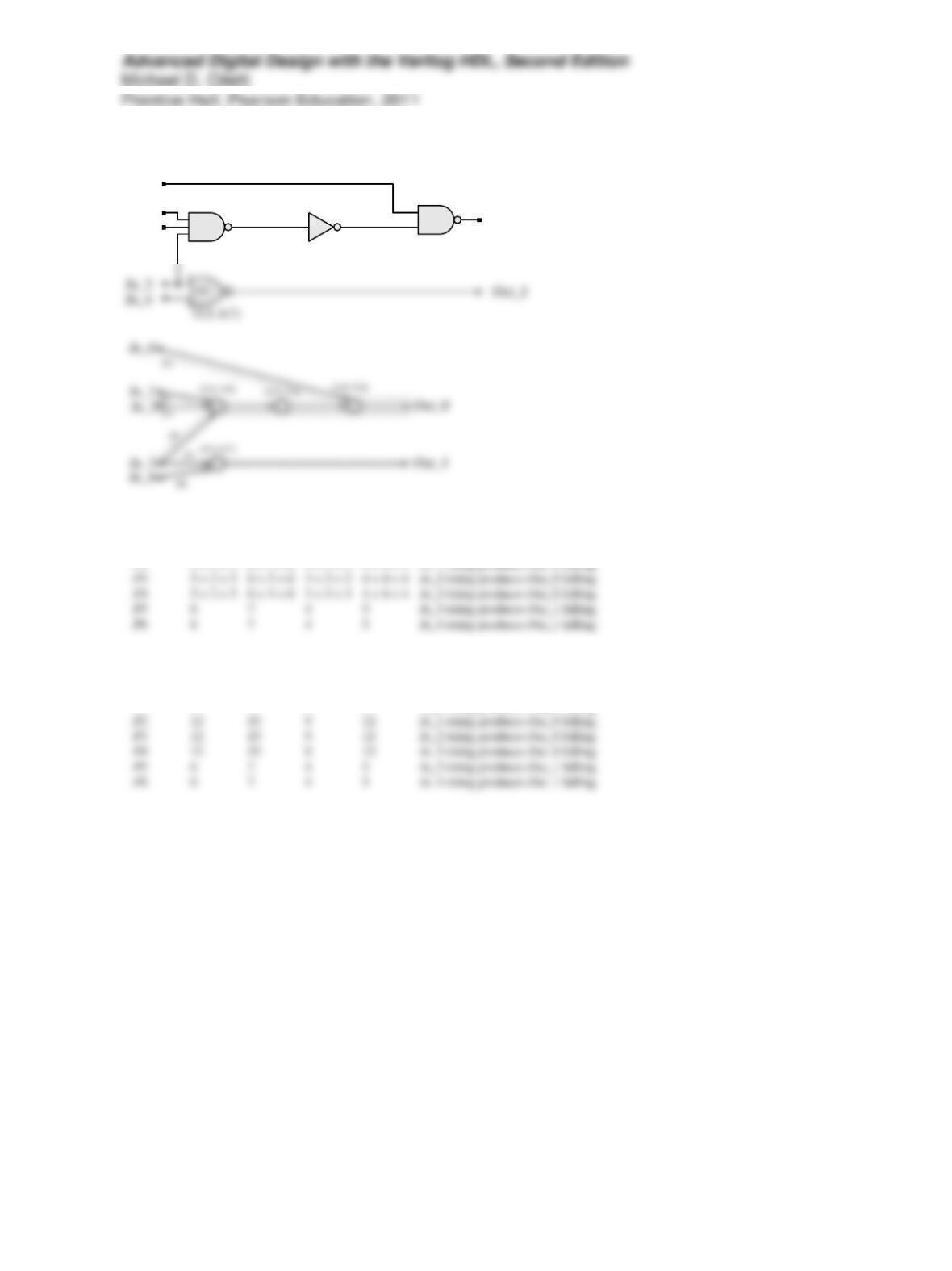
Problem 11-1
In_0
In_1
In_2
Out_0
G0
G2G3
(3:4, 5:6) (3:4, 5:6)
(2:3, 3:4)
Path Rising Output Delay Falling Output Delay
Min Max Min Max
P15634In_0 rising produces Out_0 falling
P2 5 + 2 + 5 6 + 3 + 6 3 + 3 + 3 4 + 4 + 4 In_1 rising produces Out_0 falling
Path Rising Output Delay Falling Output Delay
Min Max Min Max
P15634In_0 rising produces Out_0 falling
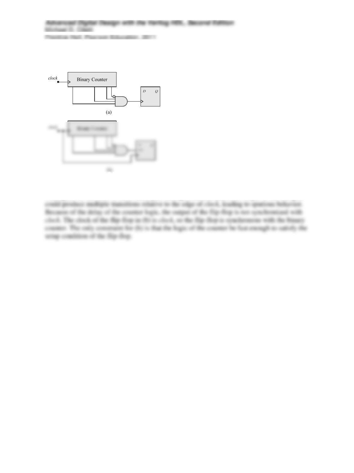
Problem 11-5
The circuit in (a) is problematic because the clock input of the flip-flop is driven by the output of
a and gate. As the cells of the counter pass through transient states, the output of the and gate
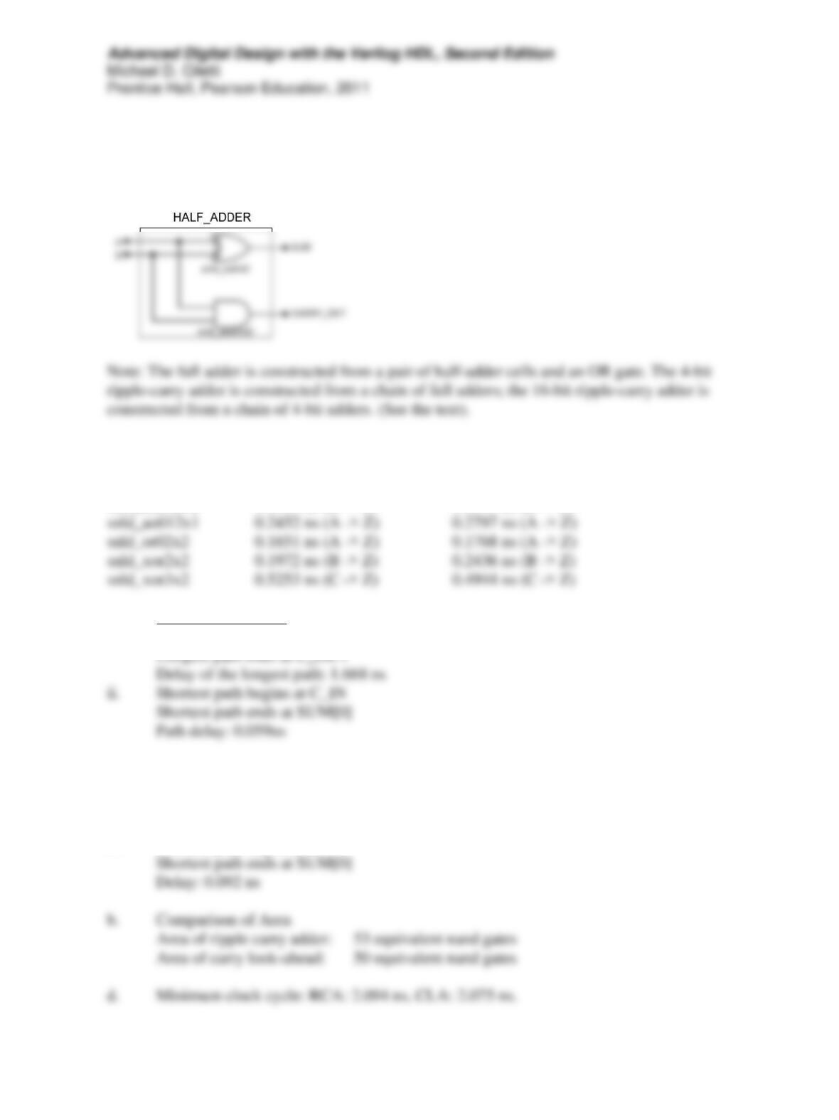
Problem 11-6
The solution below is presented as a sample of what should be developed for the particular cell
library used to create the timing analysis.
Cells used in the design:
Cell name Prop Delay (Rising) Prop Delay (Falling)
snld_and02x2 0.1505 ns (B -> Z) 0.1895 ns (B -> Z)
a. Ripple Carry Adder
i. Longest path begins at: B[0]
Carry Look-Ahead Adder
iii. Longest path begins at B[0]
Longest path ends at SUM[3]
Delay: 1.589 ns
iv. Shortest path begins at A[0]
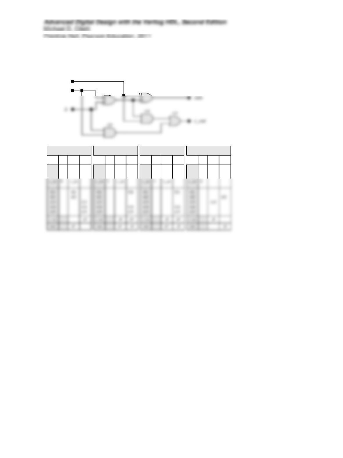
Problem 11-7
G1
G2
a
c_in
a
b
0
0
Tests for s-a-1 Faults
a
b
site#1 site
a
b
1
0
Tests for s-a-0 Faults
b
site#1 site
a
b
1
1
Tests for s-a-0 Faults
a
site#1 site
a
b
1
1
Tests for s-a-0 Faults
site#1 site
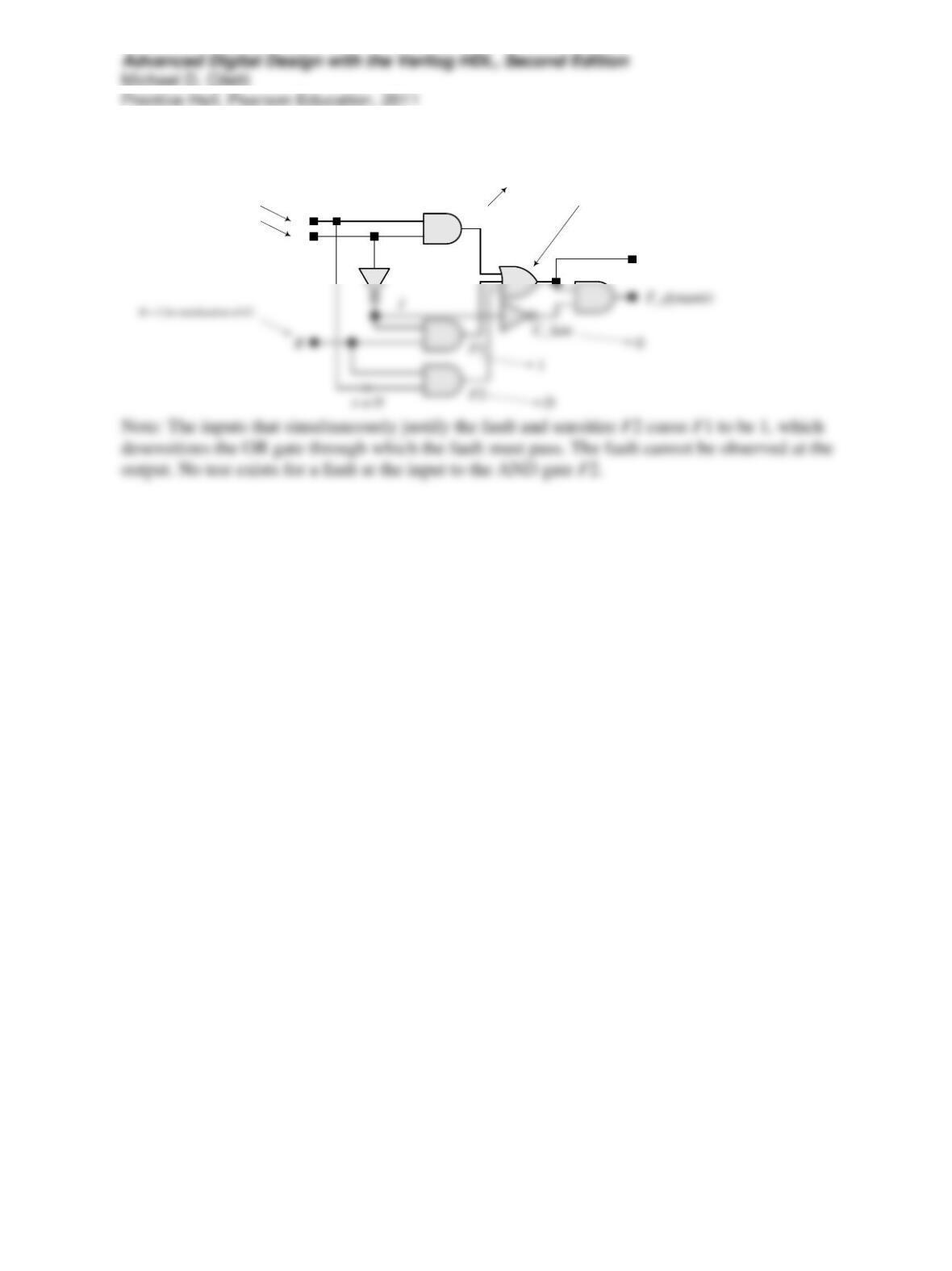
Problem 11-8
A
C
F_static
F0
A = 1 for justification
C = 0 for sensitization of F0
0
Blocked by
F1
Problem 11-9
See the solution to 11-7.
Problem 11-11
The signal reset_bar is generated at the next negative edge ofhe clock, which resets the
instruciton register to be filled with ones, causing hte mahine tobe in the bypass mode.
Problem 11-15
A glitch on TMS will take the machine to S_Run_Idle, where, with TMS no longer 0, the
machine will transition to S_Select_DR, and then to S_Select IR, before returning to S_Reset.
Problem 11-17
See the discussion at the bottom of p. 804 and Figure 11-51 in the text. The exit states allow a
Problem 11-20
If the machines in figure 11-60 enter the state Y = 0 they will remain there becasue teh inputs to the flip-
flops will be and remain 0. when the flip-flop in Figure P11-20 has Y = 0 the left-most three stages will