PROBLEM 11S.6
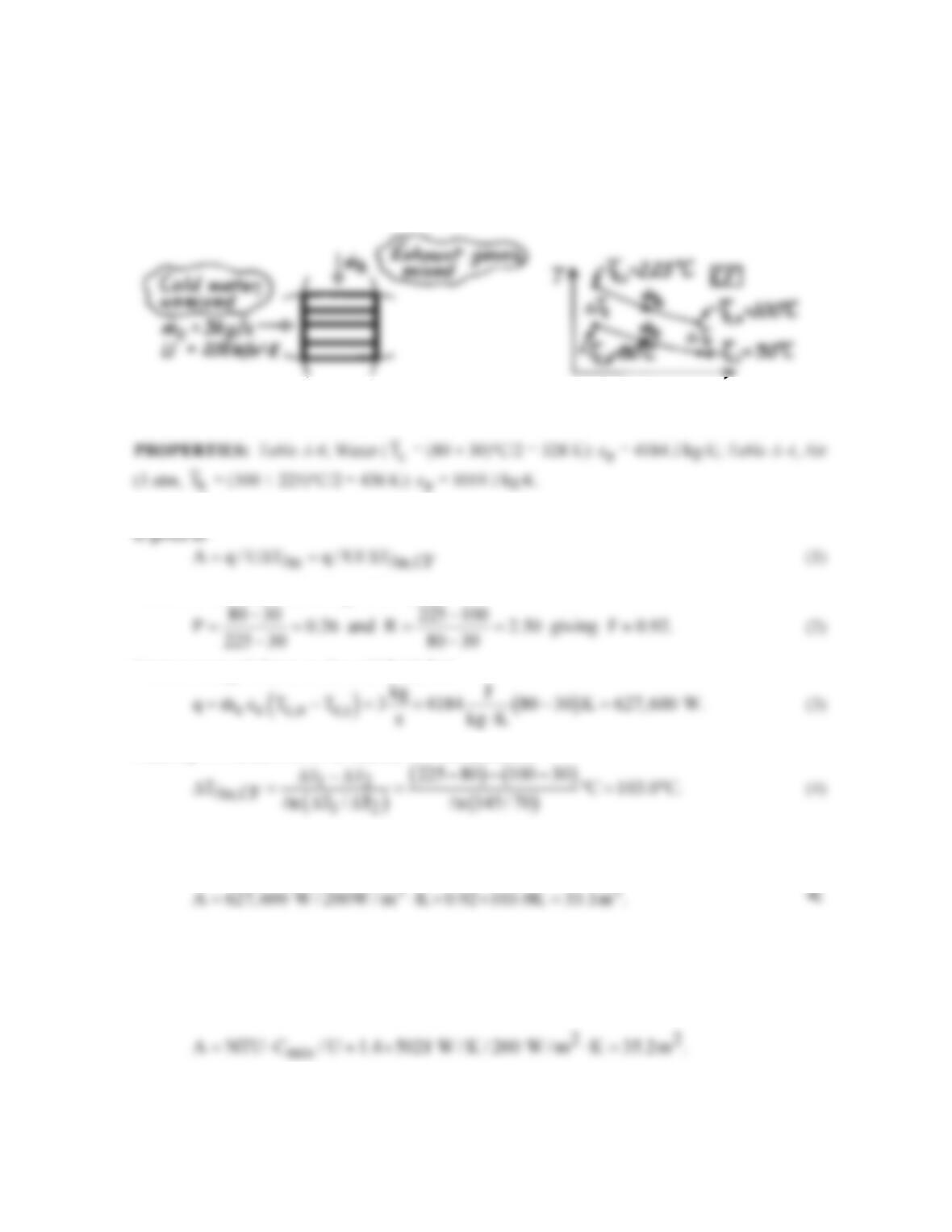
KNOWN: Single pass, cross–flow heat exchanger with hot exhaust gases (mixed) to heat water
(unmixed)
FIND: Required surface area.
SCHEMATIC:
ASSUMPTIONS: (1) Negligible heat loss to surroundings, (2) Negligible kinetic and potential
energy changes, (3) Exhaust gas properties assumed to be those of air.
ANALYSIS: The rate equation for the heat exchanger follows from Eqs. 11.14 and 11S.1. The area
where F is determined from Fig. 11S.4 using
From an energy balance on the cold fluid, find
From Eq. 11.15, the LMTD for counter-flow conditions is
Substituting numerical values resulting from Eqs. (2-4) into Eq. (1), find the required surface area to
be
COMMENTS: Note that the properties of the exhaust gases were not needed in this method of
analysis. If the e–NTU method were used, find first Ch/Cc = 0.40 with Cmin = Ch = 5021 W/K. From
Eqs. 11.18 and 11.19, with Ch = Cmin, e = q/qmax = (Th,i – Th,o)/(Th,i – Tc,i) = (225 – 100)/(225 –
30) = 0.64. Using Fig. 11.15 with Cmin/Cmax = 0.4 and e = 0.64, find NTU = UA/Cmin ≈ 1.4. Hence,
Note agreement with above result.
PROBLEM 11S.7
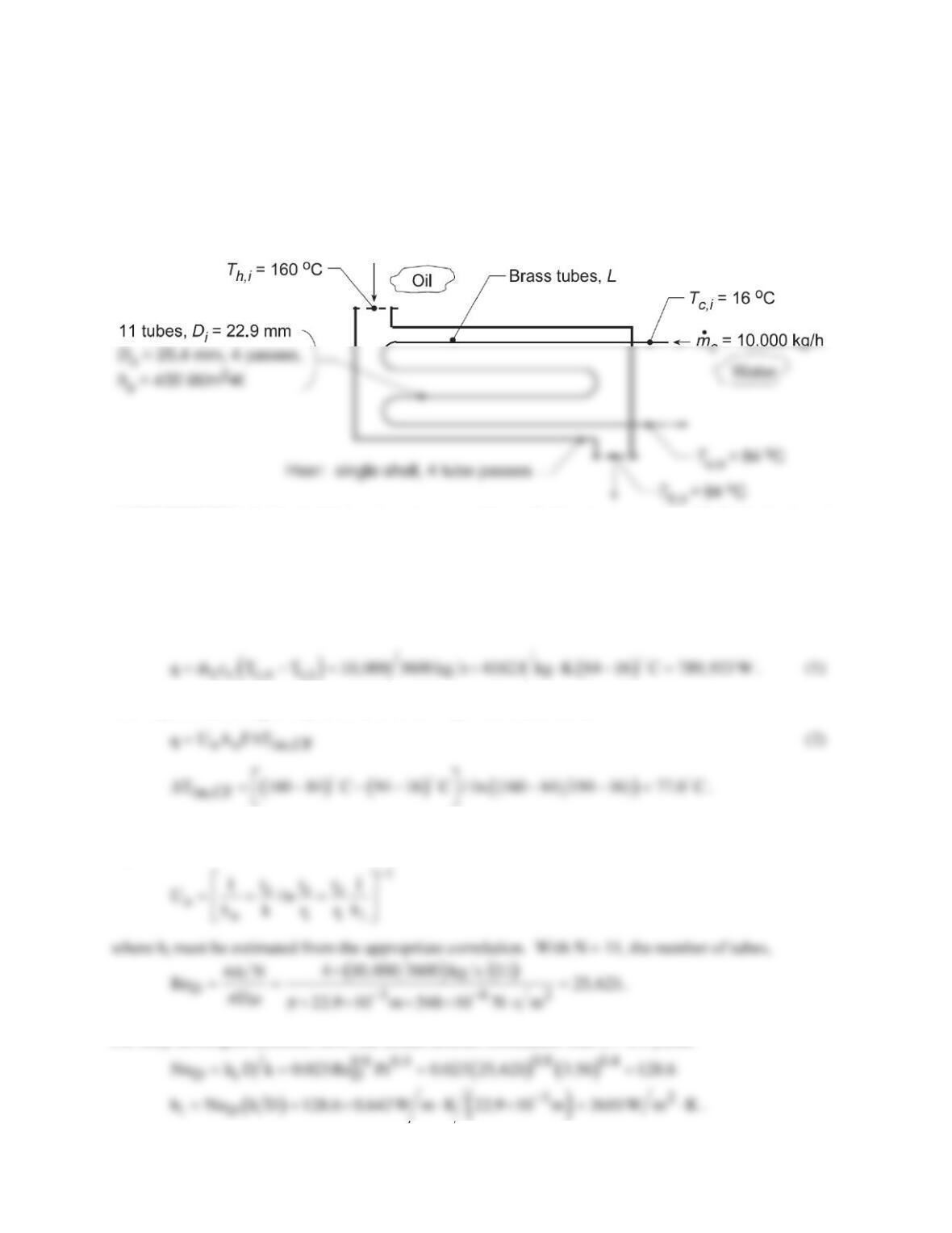
KNOWN: Conditions of oil and water for heat exchanger, one shell with 4 tube passes.
FIND: Length of exchanger tubes per pass, L; and (b) Compute and plot the effectiveness, e, fluid
outlet temperatures, Th,o and Tc,o, and water-side convection coefficient, hc , as a function of the water
flow rate for 5000 ≤
c
m
≤ 15,000 kg / h for the tube length found in part (a) with all other conditions
remaining the same.
SCHEMATIC:
ASSUMPTIONS: (1) Negligible heat loss to surroundings, (2) Constant properties, (3) Fully-developed
flow in tubes.
PROPERTIES: Table A-1, Brass (400 K): k = 137 W/m⋅K; Table A-5, Water (323 K):
ρ
= 998.1
kg/m3, k = 0.643 W/m⋅K, cp = 4182 J/kg⋅K, m = 548 × 10-6 N⋅s/m2, Pr = 3.56.
ANALYSIS: (a) From an energy balance on the water, the heat rate required is
The required tube length may be obtained from Eqs. 11.14 and 11.15,
From Fig. 11S.1, F = 0.86 using P = (84 – 16)/(160 – 16) = 0.47 and R = (160 – 94)/(84 – 16) = 0.97. From
Eq. 11.5,
For fully developed turbulent flow, the Dittus-Boelter correlation with n = 0.4 yields
Continued…
PROBLEM 11S.7 (Cont.)
Returning now to Eq. (2), find Ao, then the length,
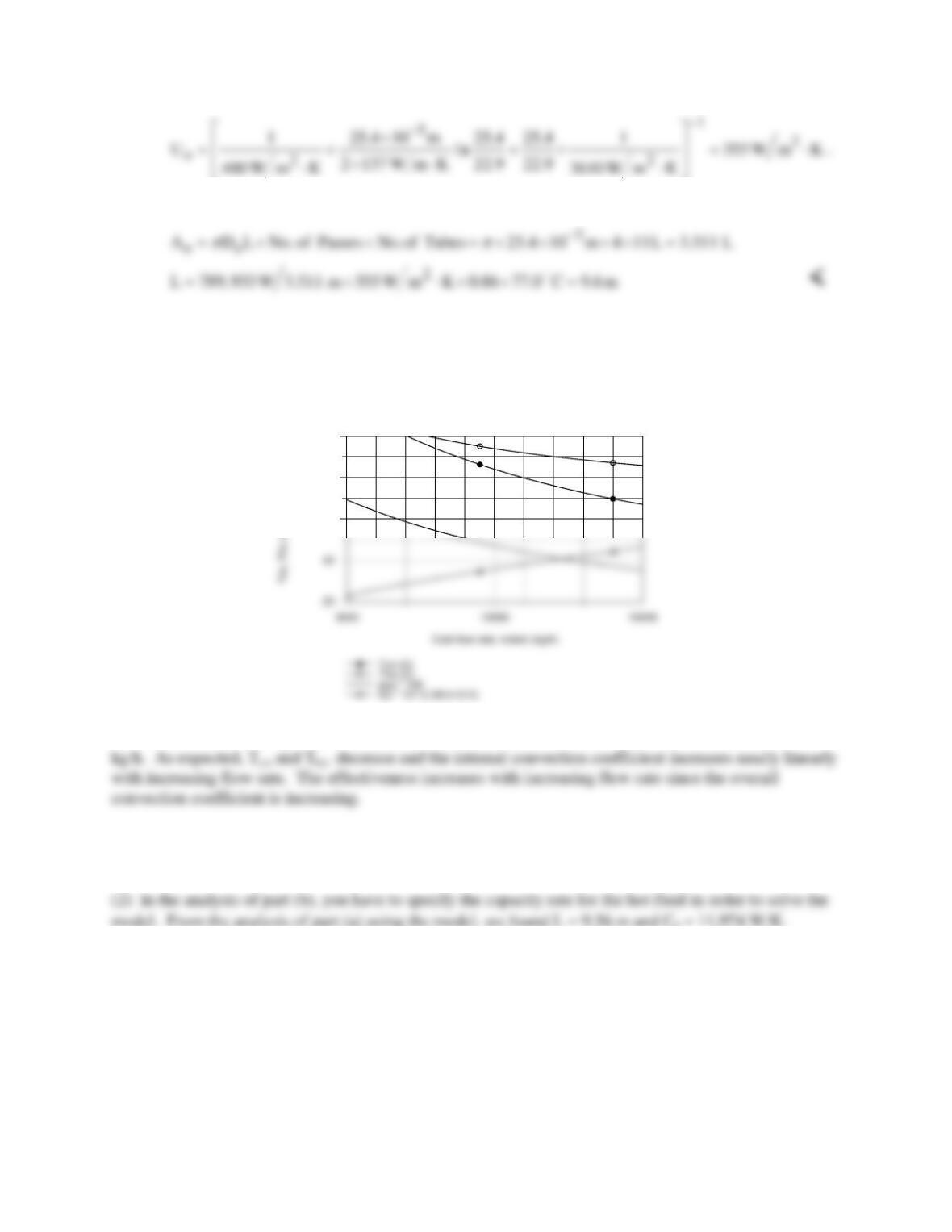
(b) Using the IHT Heat Exchanger Tool, Shell and Tube, One-shell pass and N tube passes, the
Correlation Tool, Forced Convection, Internal Flow for Turbulent, fully developed condition, and the
Properties Tool for Water, a model was developed using the effectiveness – NTU method to compute and
plot Tc,o , Th,o , e, and hi as a function of
c
m
.
60
80
100
In order to avoid a boiling condition in the cold fluid, the cold flow rate should not be less than 8000
COMMENTS: (1) The thermal resistance of the brass tubes is negligible. Since L/Di = 400, fully-
developed conditions are reasonable.
PROBLEM 11S.8
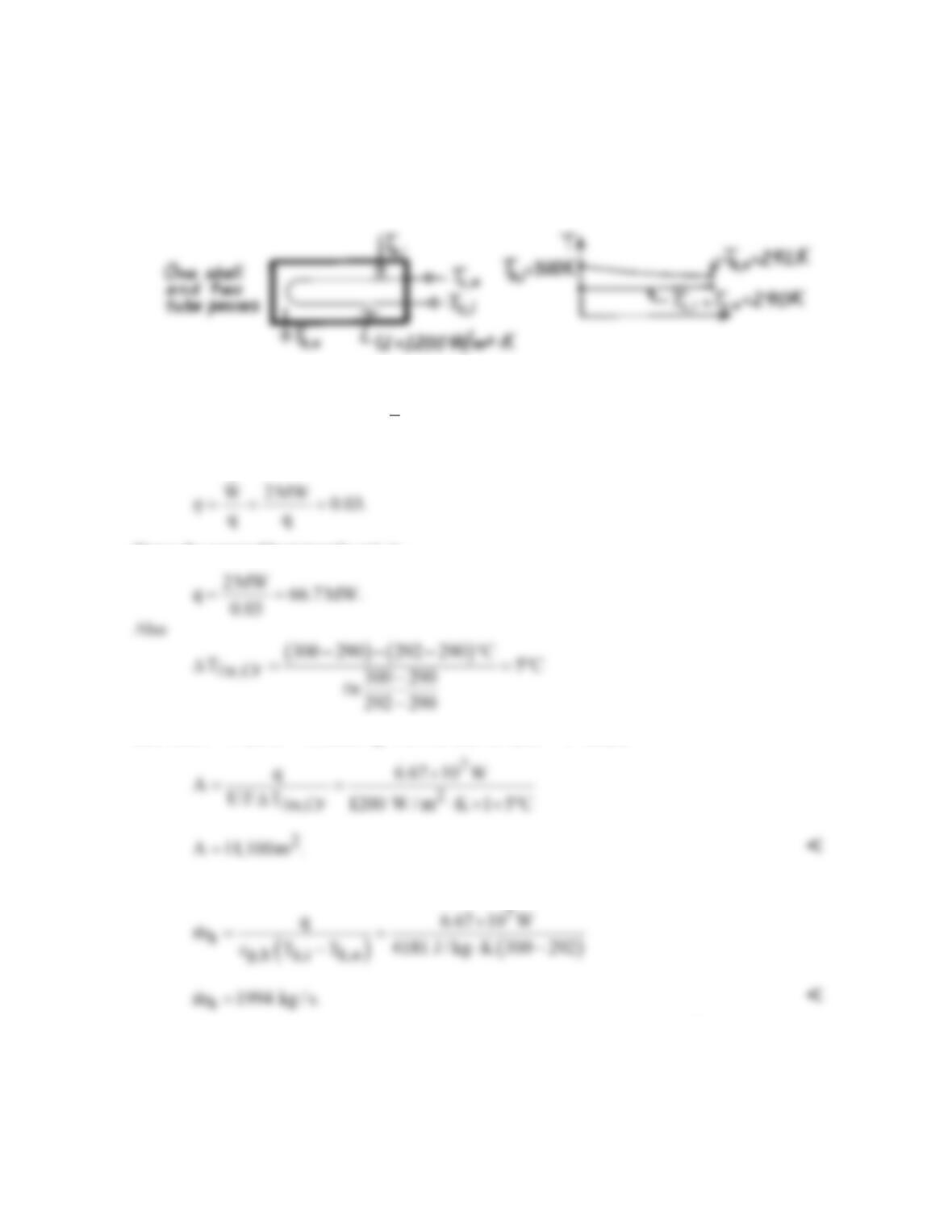
KNOWN: Power output and efficiency of an ocean energy conversion system. Temperatures and
overall heat transfer coefficient of shell-and-tube evaporator.
FIND: (a) Evaporator area, (b) Water flow rate.
SCHEMATIC:
ASSUMPTIONS: (1) Negligible heat loss to surroundings, (2) Constant properties.
PROPERTIES: Table A-6, Water (
m
T
= 296 K): cp = 4181 J/kg⋅K.
ANALYSIS: (a) The efficiency is
Hence the required heat transfer rate is
and, with P = 0 and R = ∞, from Fig. 11S.1 it follows that F = 1. Hence
(b) The water flow rate through the evaporator is
COMMENTS: (1) From the e–NTU method, (Cmin/Cmax) = 0, qmax = 8.34 × 10⁷ W, e = 0.80 and
from Fig. 11.12, NTU ≈ 1.65, giving A = 11,500 m2. (2) The required heat exchanger size is
enormous due to the small temperature differences involved.
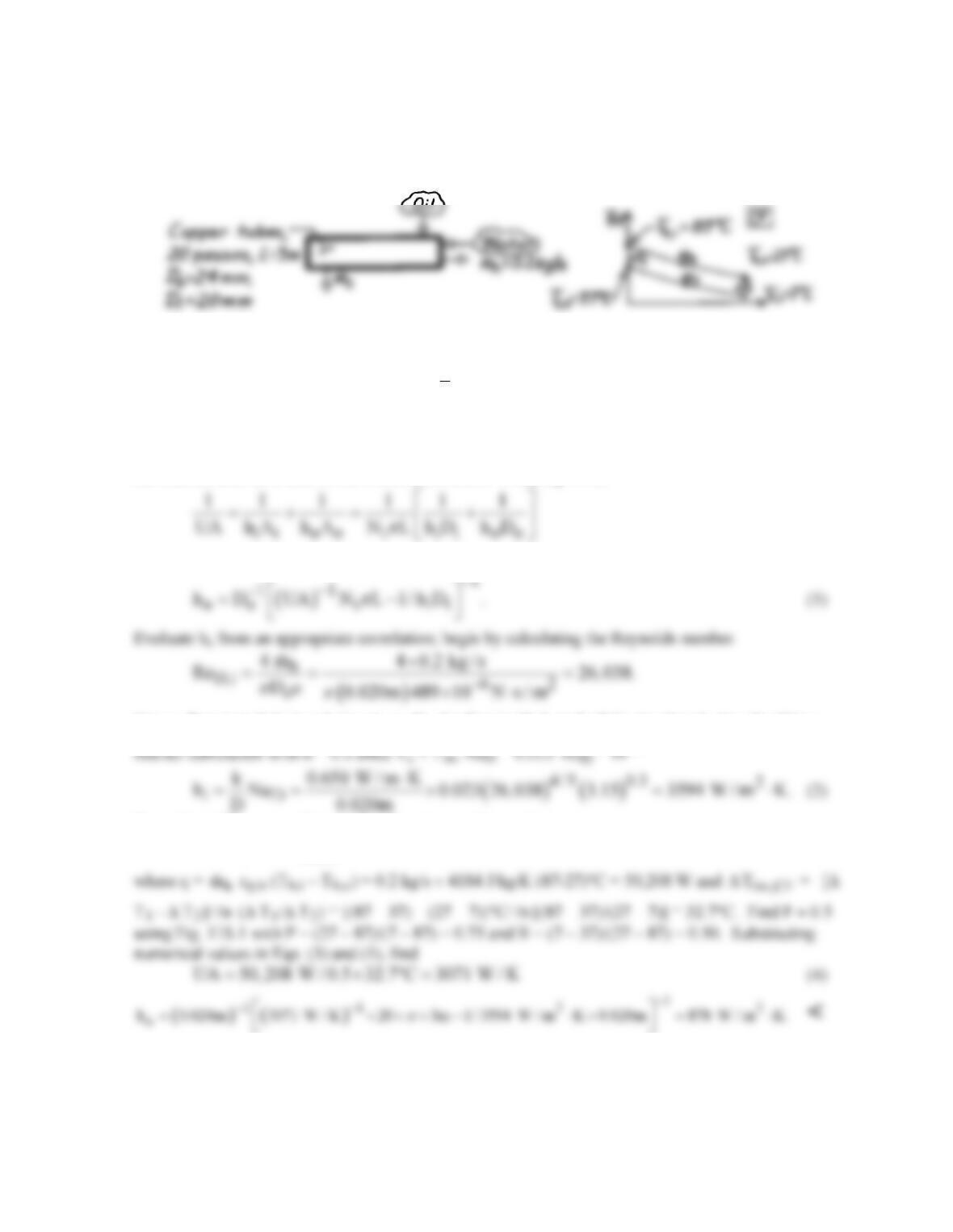
PROBLEM 11S.9
KNOWN: Shell-and-tube heat exchanger with one shell pass and 20 tube passes.
FIND: Average convection coefficient for the outer tube surface.
SCHEMATIC:
ASSUMPTIONS: (1) Negligible heat loss to surroundings, (2) Constant properties, (3) Type of oil
not specified, (4) Thermal resistance of tubes negligible; no fouling.
PROPERTIES: Table A-6, Water, liquid (
h
T
= 330 K): cp = 4184 J/kg⋅K, k = 0.650 W/m⋅K, m =
489 × 10-6 N⋅s/m2, Pr = 3.15.
ANALYSIS: To find the average coefficient for the outer tube surface, ho, we need to evaluate hi for
the internal tube flow and U, the overall coefficient. From Eq. 11.5,
where Nt is the total number of tubes. Solving for ho,
Hence, flow is turbulent and since L >> Di, the flow is likely to be fully developed. Use the Dittus–
4/5
To evaluate UA, we need to employ the rate equation, written as
m,CF
UA q / F T= ∆
(3)
COMMENTS: Using the e-NTU method: find Ch and Cc to obtain Cr = 0.5 and e = 0.75. From Eq.
11.30b,c find NTU = 3.44 and UA = 2881 W/K.
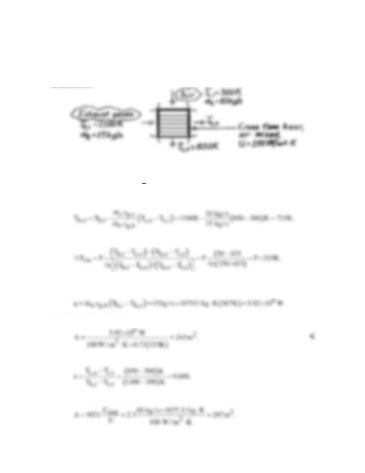
PROBLEM 11S.10
KNOWN: Flow rates and inlet temperatures of exhaust gases and combustion air used in a cross–
flow (one fluid mixed) heat exchanger. Overall heat transfer coefficient. Desired air outlet
temperature.
FIND: Required heat exchanger surface area.
SCHEMATIC:
ASSUMPTIONS: (1) Steady-state conditions, (2) Negligible heat loss to surroundings, (3) Constant
properties, (4) Gas properties are those of air.
PROPERTIES: Table A-4, Air (
m
T
≈ 700 K, 1 atm): cp = 1075 J/kg⋅K.
ANALYSIS: From Eqs. 11.6b and 11.7b,
From Eqs. 11.15, 11.17 and 11S.1,
From Fig. 11S.4, with R = (300 – 850)/(733 – 1100) = 1.50 and P = (733 – 1100)/(300 – 1100) = 0.46,
F ≈ 0.73. With
it follows from Eq. 11.14 that
COMMENTS: Using the effectiveness–NTU method, from Eq. 11.21
Hence, with Cmixed/Cunmixed = Cc/Ch = 0.67, Fig. 11.15 gives NTU ≈ 2.3. From Eq. 11.24,
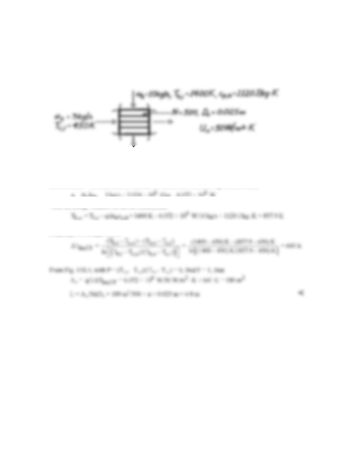
PROBLEM 11S.11
KNOWN: Flow rate, specific heat and inlet temperature of gas in cross–flow heat exchanger. Flow
rate and temperature of water which enters as saturated liquid and leaves as saturated vapor. Number
of tubes, tube diameter and overall heat transfer coefficient.
FIND: Required tube length.
SCHEMATIC:
ASSUMPTIONS: (1) Negligible heat loss to surroundings, (2) Constant gas specific heat.
PROPERTIES: Table A-6, Saturated Water, (T = 450 K): hfg = 2.024 ×10⁶ J/kg.
ANALYSIS: The heat transfer rate can be found from considering the cold fluid,
c fg
q = m h = 3 kg/s × 2.024 × 10 J/kg = 6.072 × 10 W
Then an energy balance on the hot fluid yields
From Eqs. 11.15 and 11.17,
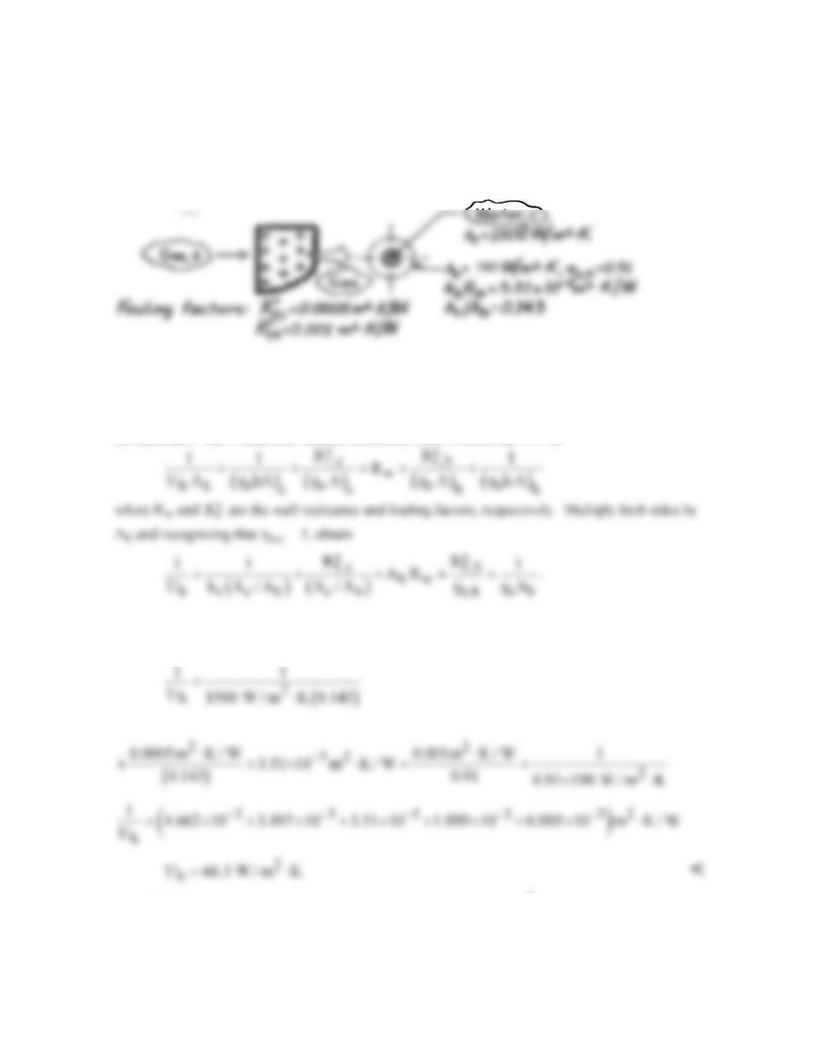
PROBLEM 11S.12
KNOWN: Compact heat exchanger (see Example 11S.2) after extended use has prescribed fouling
factors on water and gas sides.
FIND: Gas–side overall heat transfer coefficient.
SCHEMATIC:
ASSUMPTIONS: (1) Heat transfer coefficients on the inside and outside (cold- and hot-sides) are
the same as for the unfouled condition, (2) Temperature effectiveness of the finned hot side surface is
the same as for the unfouled condition.
ANALYSIS: The overall heat transfer coefficient follows from Eq. 11.1 as
Substitute numerical values from Example 11S.2 results (hh, ho,h, Ah Rw, Ac/Ah) and those from the
problem statement
( )
f,h f,c c
R ,R ,h
′′ ′′
to find,
COMMENTS: For the unfouled condition, we found Uh = 100 W/m2⋅K from Example 11S.2. Note
that the thermal resistance of the tube–fin material is negligible and that fouling has a significant
effect, reducing Uh by 34%.
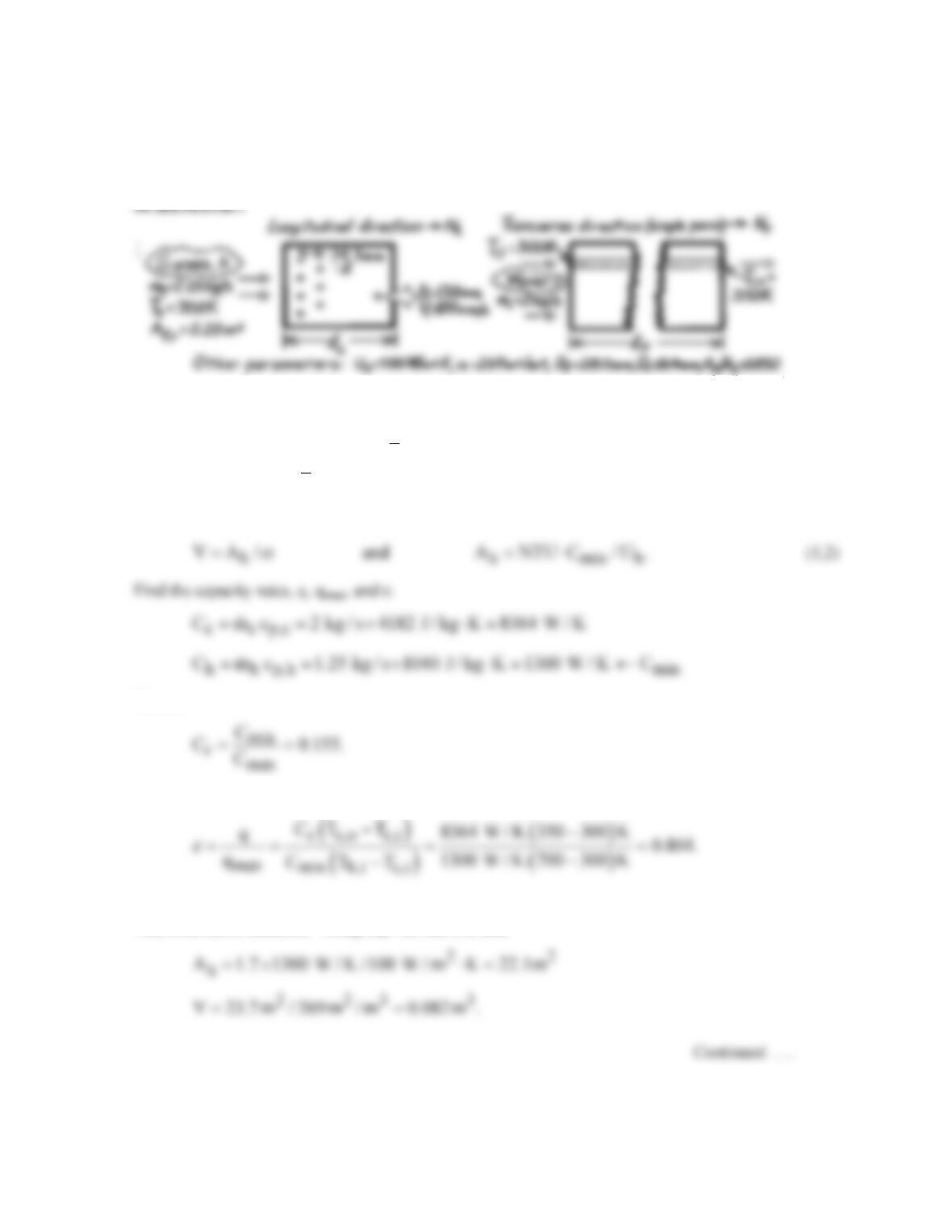
PROBLEM 11S.13
KNOWN: Compact heat exchanger with prescribed core geometry and operating parameters.
FIND: Required heat exchanger volume; number of tubes in the longitudinal and transverse
directions, NL and NT; required tube length.
ASSUMPTIONS: (1) Negligible heat loss to surroundings, (2) Single pass operation, (3) Gas
properties are those of air.
PROPERTIES: Table A-6, Water (
c
T
= 325 K): ρ = 987.2 kg/m3, cp = 4182 J/kg⋅K; Table A-4, Air
(Assume Th,o ≈ 400 K,
h
T
≈ 550 K, 1 atm): cp = 1040 J/kg⋅K.
ANALYSIS: To find the Hxer volume, first find Ah using the e-NTU method. By definition,
Hence,
It follows that
With e = 0.804 and Cr = 0.155, find NTU ≈ 1.7 from Fig. 11.14 for a single-pass, cross flow Hxer
with both fluids unmixed. Using Eqs. (2) and (1), find
PROBLEM 11S.13 (Cont.)
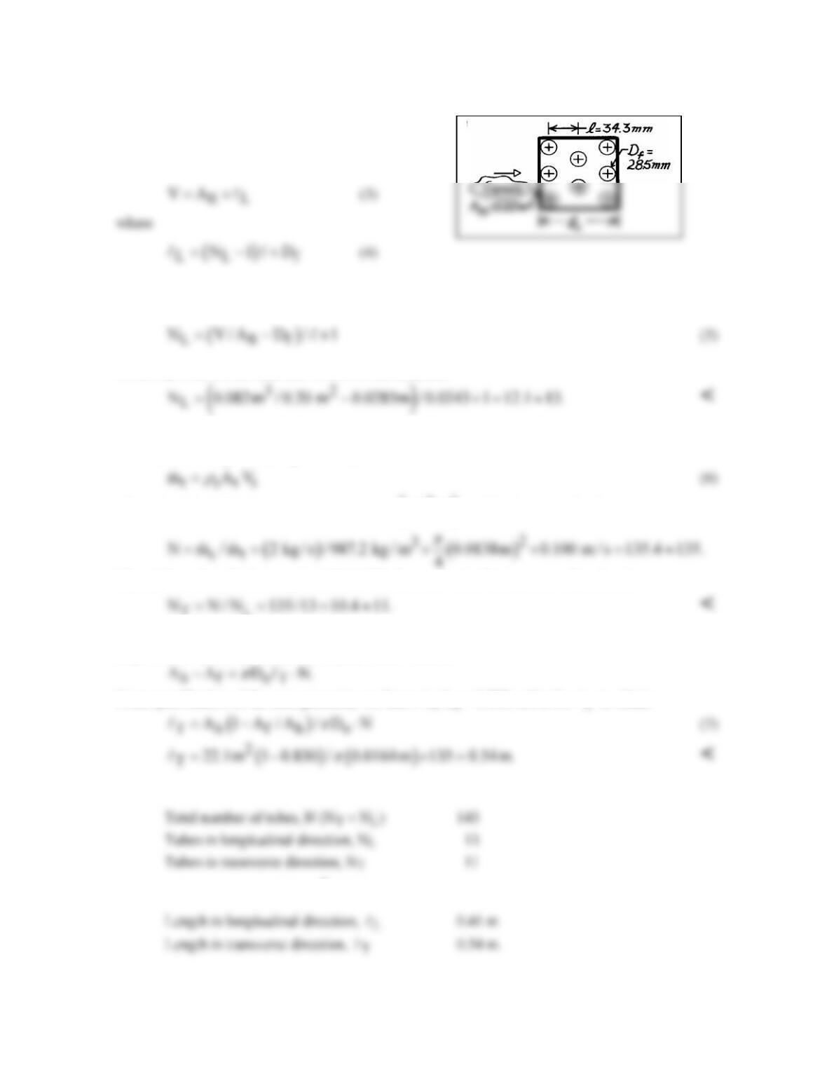
To determine the number of tubes in the
longitudinal direction, consider the tubular
arrangement in the sketch. The Hxer
volume can be written as
and NL is the number of tubes in the longitudinal direction. Combining Eqs. (3) and (4) and
substituting numerical values, find
where Df is the overall diameter of the finned tube, and
To determine the number of tubes in the transverse direction, compare the overall water flow rate
c
m
with that for a single tube,
t
m.
That is,
where At is the tube inner cross-sectional area
()
2
i
D /4
π
and Vi the internal velocity. Hence,
The total number of tubes required, N, is 135; the number in the transverse direction is
TL
To determine the water tube length, recognize that the total area (Ah), less that of the finned surfaces
(Af), will be that of the water tube surface area. That is,
From specification of the core geometry, we know Af/Ah = 0.830; solve for
to obtain
COMMENTS: In summary we find that
with a total surface area of 22.1 m2. The length of the exchanger is
PROBLEM 11S.14
KNOWN: Compact heat exchanger geometry, gas–side flow rate and inlet temperature, water–side
convection coefficient, water flow rate, and water inlet and outlet temperatures.
FIND: Gas–side overall heat transfer coefficient. Required heat exchanger volume.
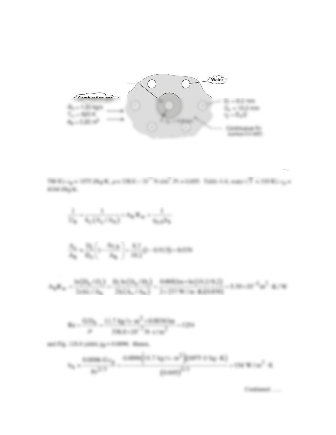
SCHEMATIC:
T = 290 K
c,i
T = 370 K
c,o
h = 1500 W/m -K
c 2
Hypothetical
circular fin
ASSUMPTIONS: (1) Gas has properties of atmospheric air at an assumed mean temperature of 700
K, (2) Negligible fouling, (3) Negligible heat exchange with the surroundings.
PROPERTIES: Table A-1, aluminum (T ≈ 300 K): k = 237 W/m⋅K. Table A-4, air (p = 1 atm,
T
=
ANALYSIS: For the prescribed heat exchanger core,
where
The product of Ah and the wall conduction resistance is
With a gas–side mass velocity of G =
h fr
m/ A
s
= 1.25 kg/s/0.534 × 0.20 m2 = 11.7 kg/s⋅m2,
PROBLEM 11S.14 (Cont.)
With r2c = r2 + t/2 = 15.8 mm + 0.330 mm/2 = 15.97 mm, r2c/r1 = 15.97/5.1 = 3.13, L = r2 – r1 = 10.7
mm, Lc = L + t/2 = 10.87 mm = 0.0109m, Ap = Lct = 3.59 × 10⁻⁶ m2, and
3/2
c
L
(hh/kAp)1/2 = 0.484,
Fig. 3.20 yields hf ≈ 0.77. Hence,
( ) ( )
11
1 2 52 2 2
h
U 1500 W / m K 0.07 5.39 10 m K / W 0.79 154 W / m K 0.0183 m K/W
−−
−−
= ⋅× + × ⋅ + × ⋅ = ⋅
With q = Cc (Tc,o – Tc,i) = 4184 W/K × 80 K = 3.35 × 10⁵ W, qmax = Cmin (Th,i – Tc,i) = 1344 W/K ×
535 K = 7.19 × 10⁵ W, e = 0.466 and Cr = 0.321. From Figure 11.14, we then obtain NTU ≈ 0.65.
The required gas-side surface area is then
With α = 587 m2/m3, the required volume is
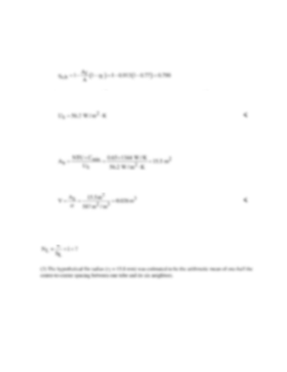
COMMENTS: (1) Although Uh is small and Ah larger for the continuous fins than for the circular
fins of Example 11S.2, the much larger value of α renders the volume requirement smaller.
(2) The heat exchanger length is L = V/Afr = 0.132 m, and the number of tube rows is
PROBLEM 11S.15
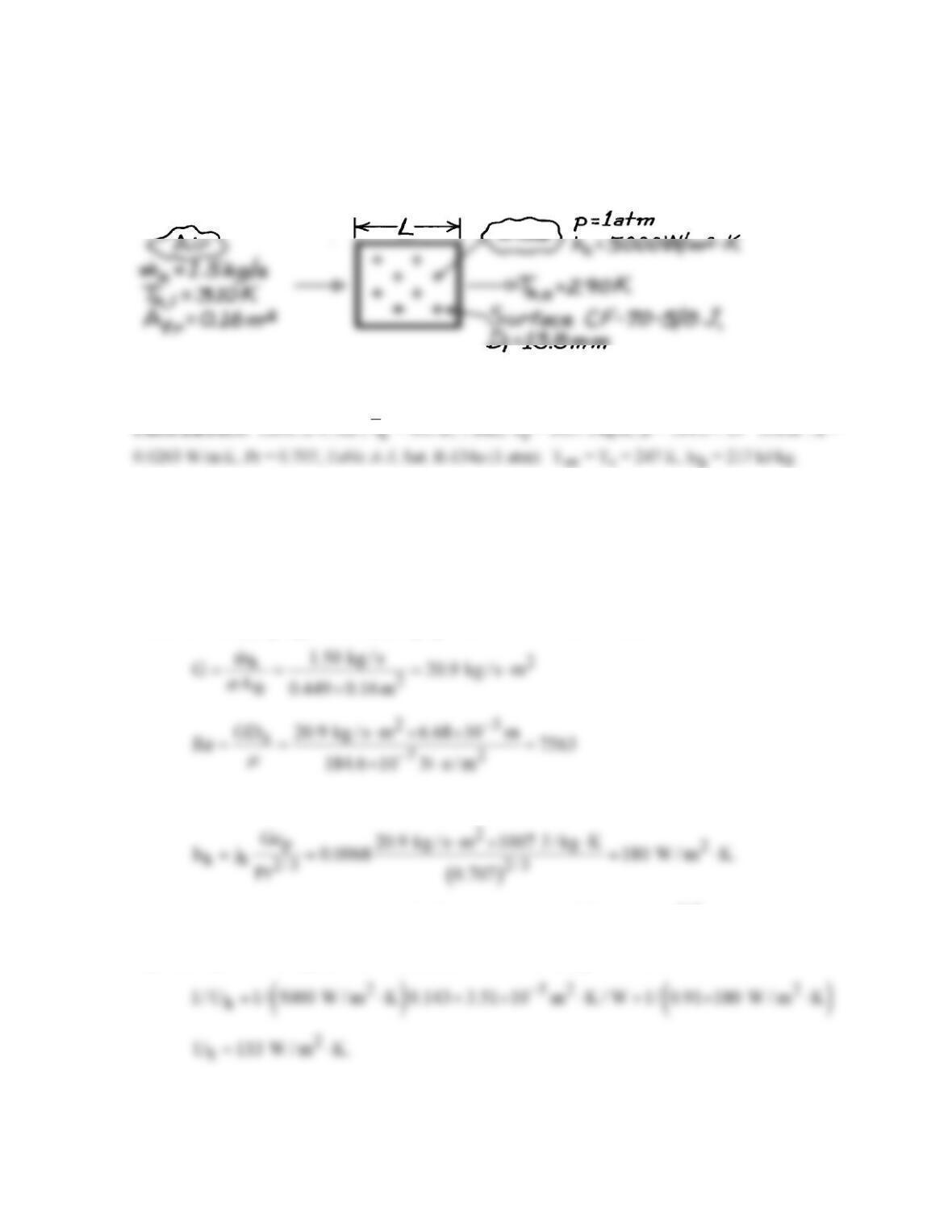
KNOWN: Cooling coil geometry. Air flow rate and inlet and outlet temperatures. Refrigerant–134a
pressure and convection coefficient.
FIND: Required number of tube rows.
SCHEMATIC:
ASSUMPTIONS: (1) Negligible fouling, (2) Constant properties, (3) Negligible heat loss to
surroundings.
ANALYSIS: The required number of tube rows is
( )
L fL
N L D /S 1=−+
where
( )
fr h h min h
L V / A V A / A NTU C / U
α
= = =
( )
h c c h h w o,h h
1/ U 1/ h A / A A R 1/ h .
h
= ++
From Ex. 11S.2, (Ac/Ah) = 0.143 and AhRw = 3.51 × 10⁻⁵ m2⋅K/W. With
and Fig. 11S.5 gives jH ≈ 0.0068. Hence,
With Lc = 6.18 mm and Ap = 1.57 × 10⁻⁶ m2 from Ex. 11S.5,
( )
1/2
3/2
chp
L h / kA
= 0.338 and, from
Fig. 3.20, hf ≈ 0.89 for r2c/r1 = 1.75. Hence, as in Ex. 11S.5, ho,h = 0.91 and
Continued …..
PROBLEM 11S.15 (Cont.)
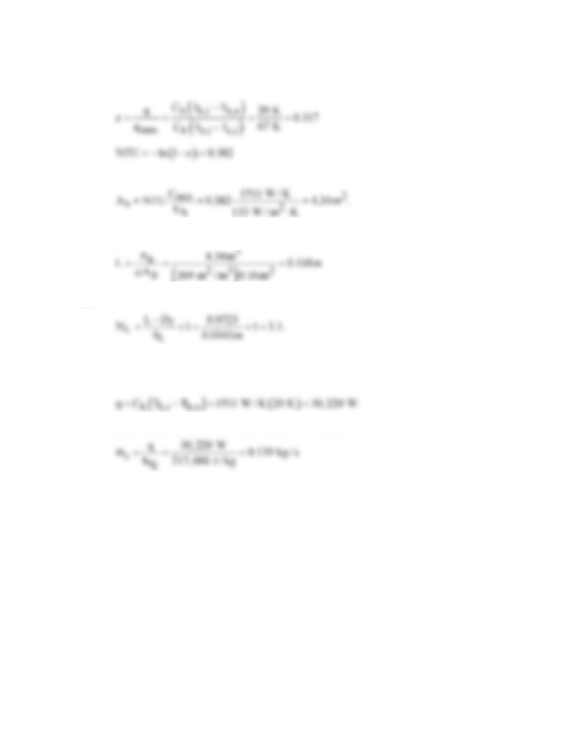
With Cmin/Cmax = 0 and Cmin =
h p,h
mc
= 1511 W/K,
and
Hence,
()
and
Hence, three or more rows must be used. <
COMMENTS: For the prescribed operating conditions, the heat rate would be
If R-134a enters the tubes as saturated liquid, a flow rate of at least
would be needed to maintain saturated conditions in the tubes.
PROBLEM 11S.16
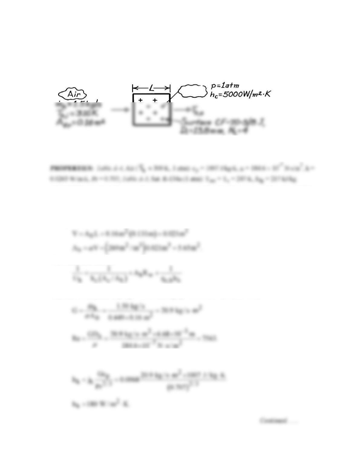
KNOWN: Cooling coil geometry. Air flow rate and inlet temperature. R–134a pressure and
convection coefficient.
FIND: Air outlet temperature.
SCHEMATIC:
ASSUMPTIONS: (1) Negligible fouling, (2) Constant properties, (3) Negligible heat loss to
surroundings.
ANALYSIS: To obtain the air outlet temperature, we must first obtain the heat rate from the e–NTU
method. To find Ah, first find the heat exchanger length,
( ) ( )
L Lf
L N 1 S D 3 0.0343m 0.0285 m 0.131m.≈ − += + =
Hence,
The overall coefficient is
where Ex. 11S.2 yields (Ac/Ah) = 0.143 and AhRw = 3.51 × 10⁻⁵ m2⋅K/W. With
Fig. 11S.5 gives jH ≈ 0.0068. Hence,
R-134aR-134a
PROBLEM 11S.16 (Cont.)
With Lc = 6.18 mm and Ap = 1.57 × 10⁻⁶ m2 from Ex. 11S.2,
( )
1/2
3/2
chp
L h / kA
= 0.338 and, from
Fig. 3.20, hf ≈ 0.89 for r2c/r1 = 1.75. Hence, as in Ex. 11S.2, ho,h = 0.91 and
h
U 133 W / m K.= ⋅
With
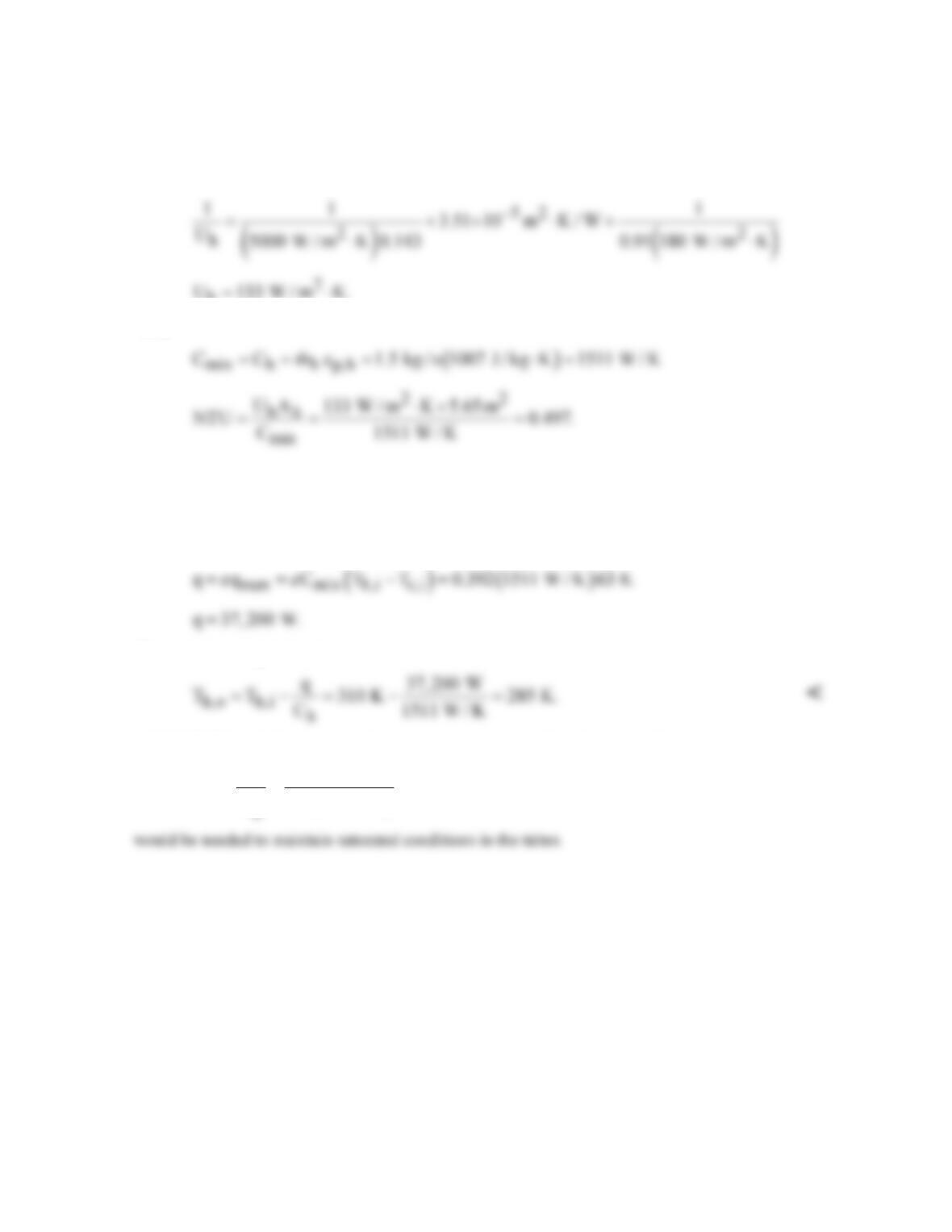
With Cmin/Cmax = 0, Eq. 11.35a yields
( ) ( )
1 exp NTU 1 exp 0.497 0.392.
e
=−− =−− =
Hence,
The air outlet temperature is
COMMENTS: If R-134a enters the tubes as saturated liquid, a flow rate of at least
cfg
q 37, 200 W
m 0.171 kg / s
h 217,000 J / kg
= = =
PROBLEM 11S.17
KNOWN: Cooling coil geometry. Gas flow rate and inlet temperature. Water pressure, flow rate
and convection coefficient.
FIND: Required number of tube rows.
SCHEMATIC:
ASSUMPTIONS: (1) Negligible fouling, (2) Constant properties, (3) Negligible heat loss to
surroundings.
PROPERTIES: Table A-4, Air (
h
T
≈ 725 K, 1 atm): cp = 1081 J/kg⋅K, m = 346.7 × 10⁻⁷
ANALYSIS: The required number of tube rows is
f
LL
LD
N1
S
−
= +
where
From Ex. 11S.2, (Ac/Ah) ≈ 0.143 and
( )
( )
( ) ( )
( )( )
i oi 42
hw ch
D ln D / D 0.0138 m ln 16.4 /13.8
A R 5.55 10 m K / W.
2k A / A 2 15 W / m K 0.143
−
= = =×⋅
⋅
With
and Fig. 11.16S.5 gives jh ≈ 0.009. Hence,
PROBLEM 11S.17 (Cont.)
With r2c/r1 = 1.75, Lc = 6.18 mm and Ap = 1.57 × 10⁻⁶ m2 from Ex. 11.6,
( )
1/2
3/2
chp
L h / kA
=
1.52 and Fig. 3.20 gives hf ≈ 0.40. Hence,
A
Hence,
With
find
From Eq. 11.35b
Hence,
COMMENTS: The gas outlet temperature is
PROBLEM 11S.18
KNOWN: Cooling coil geometry. Gas flow rate and inlet temperature. Water pressure and
convection coefficient.
FIND: Gas outlet temperature.
SCHEMATIC:
ASSUMPTIONS: (1) Negligible fouling, (2) Constant properties, (3) Negligible heat loss to
surroundings.
ANALYSIS: To obtain Th,o, first obtain q from the e-NTU method. To determine NTU, Ah must be
found from knowledge of L.
Hence,
The overall coefficient is
From Ex. 11S.2, (Ac/Ah) ≈ 0.143 and
With
and Fig. 11S.5 gives jH ≈ 0.009. Hence,
Continued …..
PROBLEM 11S.18 (Cont.)
With r2c/r1 = 1.75, Lc = 6.18 mm and Ap = 1.57 × 10⁻⁶ m2 from Ex. 11.6,
( )
1/2
3/2
chp
L h / kA
=
1.52 and Fig. 3.20 gives hf ≈ 0.40. Hence,
Hence,
With
Since Cmin/Cmax = 0, Eq. 11.35a gives
Hence,
and
COMMENTS: (1) The assumption of
h
T = 725 K is good.
(2) If water enters the tubes as saturated liquid, a flow rate of at least