Integrate:
REVIEW
Possible problems with this solution: The Reynolds number is very close to the point
where turbulent flow will occur and this would be an unstable condition. The flow
might alternate between turbulent and laminar flow.
101
10.65: PROBLEM DEFINITION
Situation:
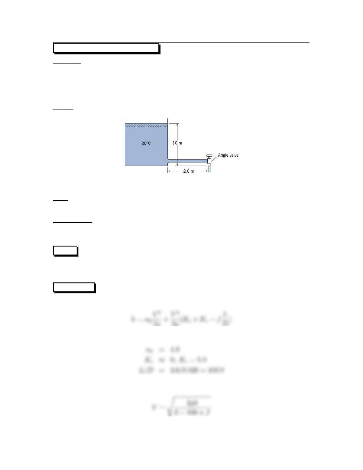
Water exits a tank through a short galvanize iron pipe.
Dtank =2m,Dpipe =26mm.
Lpipe =2.6m,z
1=10m.
Fully open angle valve: Kv=5.0.
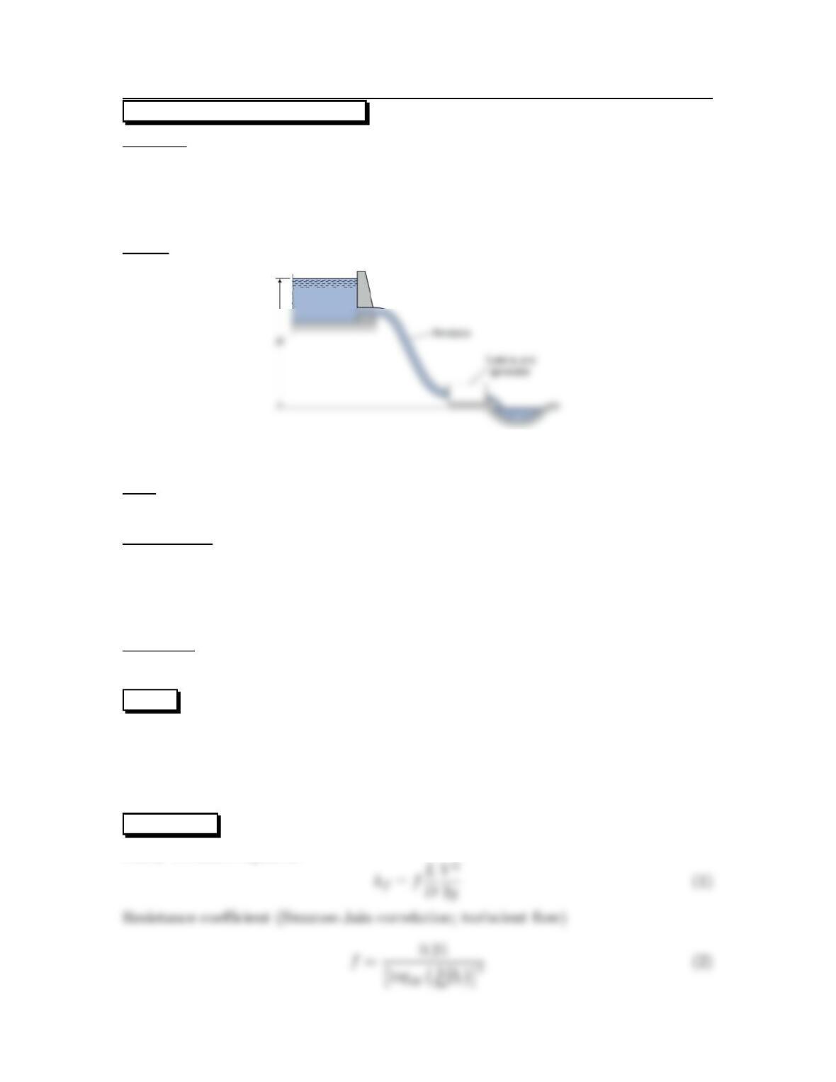
Sketch:
Find:
Time required for the water level in tank to drop from 10 m to 2 m.
Assumptions:
Thepipeentranceissmooth: Ke≈0
The kinetic energy correction factor in the pipe is α2=1.0
PLAN
Apply the energy equation from the top of the tank (location 1) to the exit of the
angle valve (location 2).
SOLUTION
Energy equation
2g+V2
2g(Ke+Kv+fL
D)
Term by term analysis
Combine equation and express Vin terms of h
Sand roughness height
102
Rate of decrease of height
REVIEW
1. When valves are tested to evaluate Kvalve the pressure taps are usually connected
2. The velocity exiting the valve will probably be highly non-uniform; therefore,
this solution should be considered as an approximation only.
103
10.66: PROBLEM DEFINITION
Situation:
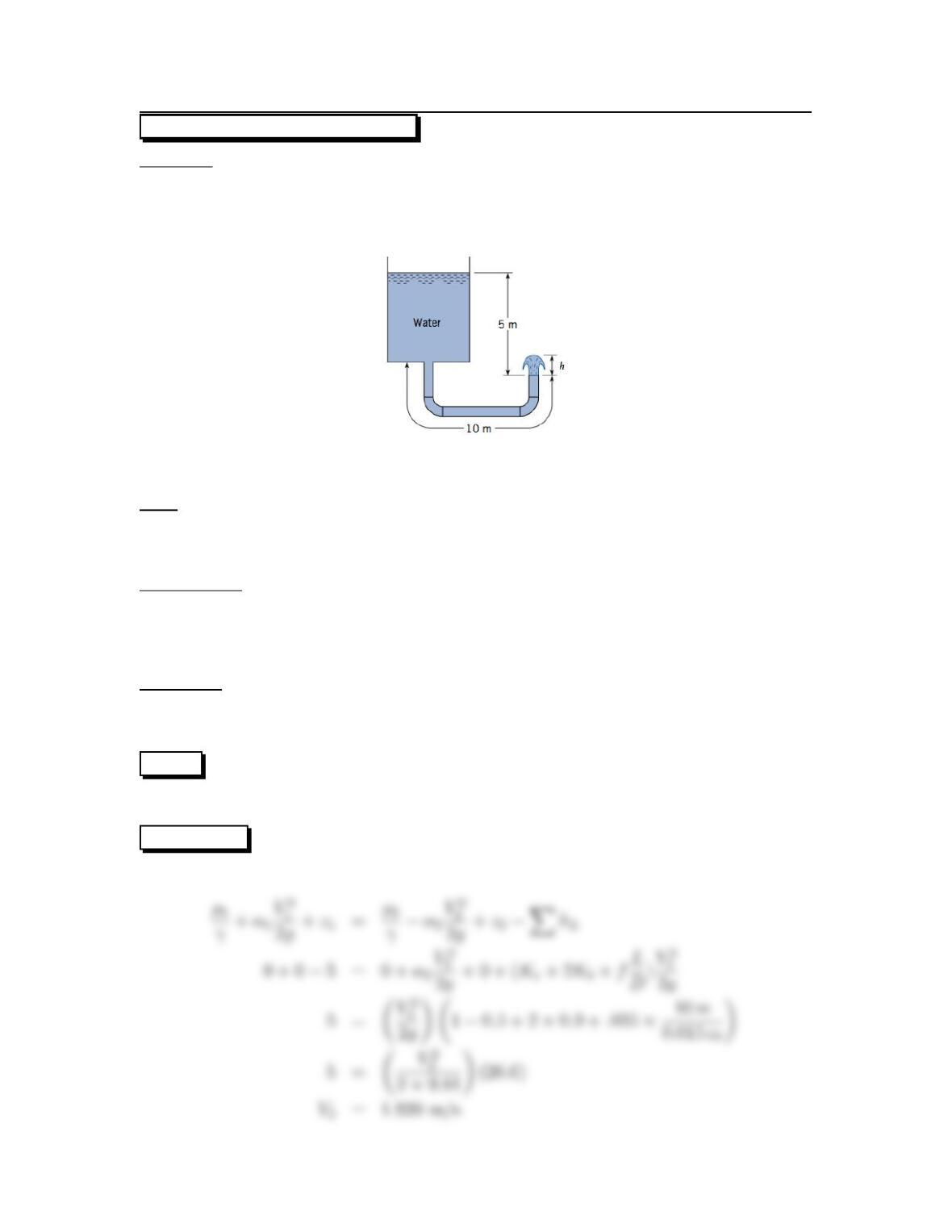
Water drains from a tank, passes through a pipe and then jets upward.
D=1.5cm,L=10m,∆z=5m.
Two 90 ◦elbows in pipe.
Find:
(a) Exit velocity of water (m/s).
(b) Height of water jet (cm).
Assumptions:
Thepipeisgalvanizediron.
Thewatertemperatureis20
oCsoν=10
−6m2/s.
Relative roughness ks/D =.015/1.5=0.01. Start iteration at f=0.035.
Properties:
From Table 10.4 ks=0.15 mm =0.015 cm.
From Table 10.5 Kb=0.9and Ke=0.5.
PLAN
Apply the energy equation from the water surface in the tank to the pipe outlet.
SOLUTION
Energy equation
104
Reynolds number
Resistance coefficient (new value)
Recalculate V2with this new value of f
Energy equation (from the pipe outlet to the top of the water jet)
105
10.67: PROBLEM DEFINITION
Situation:
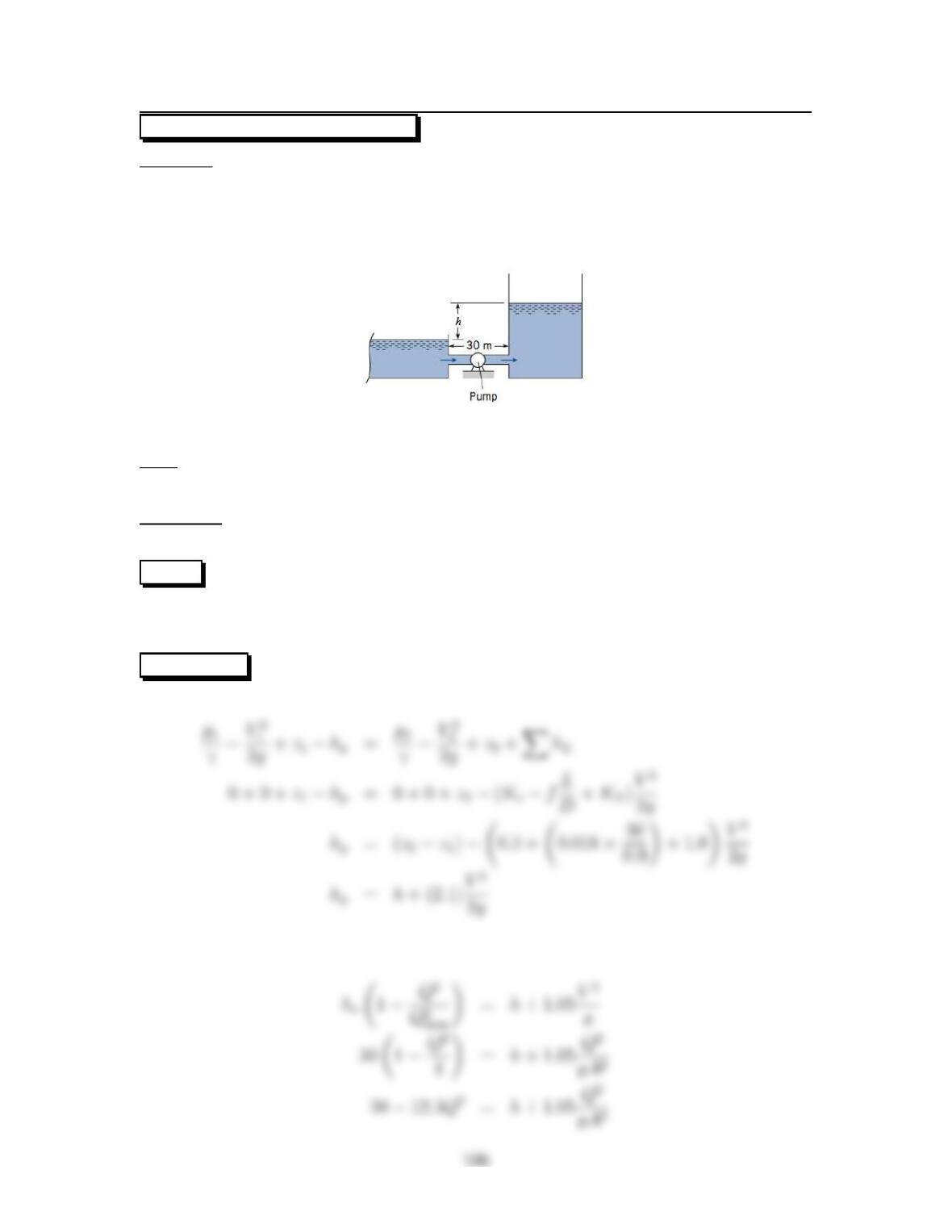
A pump operates between a reservoir and a tank.
hp=ho(1 −Q2/Q2
max),ho=50m.
Qmax =2m
3/s,f=0.18.
D=90cm,Atan k=100m
2.
Find:
Time to fill tank to 40 meters.
Properties:
From Table 10.5: Ke=0.5and KE=1.0.
PLAN
Apply the energy equation from the reservoir water surface to the tank water surface.
The head losses will be due to entrance, pipe resistance, and exit.
SOLUTION
Energy equation
But the head supplied by the pump is ho(1 −(Q2/Q2
max)) so
Thedischargeintothetankandtherateofwaterlevelincreaseisrelatedby
107
10.68: PROBLEM DEFINITION
Situation:
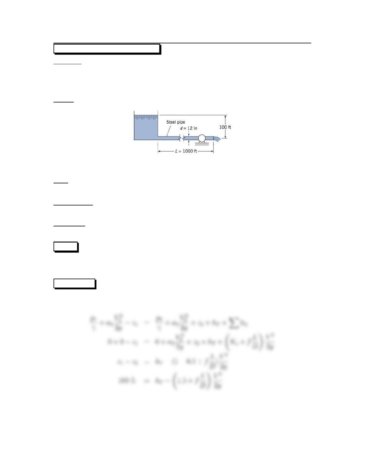
Water flows out of reservoir, through a steel pipe and a turbine.
Q=5ft
3/s,η=0.8,∆z=100ft.
D=12in,L= 1000 ft.
Sketch:
Find:
Power delivered by turbine.
Assumptions:
Turbulent flow, so α2≈1.
Properties:
Water (70oF), Table A.5: ν=1.06 ×10⁻⁵ft2/s
PLAN
Apply the energy equation from the reservoir water surface to the jet at the end of
the pipe.
SOLUTION
Energy equation
108
But
v=6.0×10⁵
From Fig. 10.14 (in EFM10e) f=0.015 for ks/D =0.000167.Then
Power equation
109
10.69: PROBLEM DEFINITION
Situation:
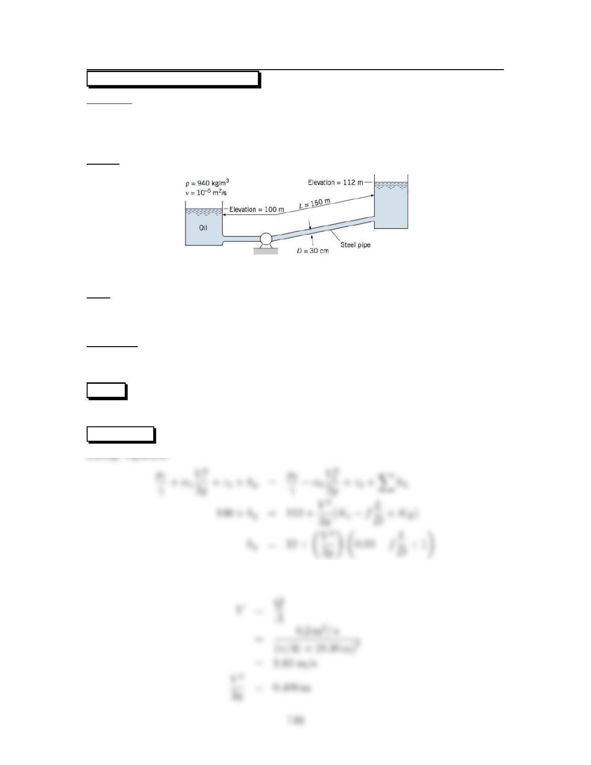
Oil is pumped from a lower reservoir to an upper reservoir through a steel pipe.
D=30cm,Q=0.20 m3/s.
z1=100m,z
2=112m,L=150m.
Sketch:
Find:
(a) Pump power.
(b) Sketch an EGL and HGL.
Properties:
ρ=940kg/m3,v=10
−5m2/s.
From Table 10.4 ks=0.046 mm
PLAN
Apply the energy equation between reservoir surfaces .
SOLUTION
Flow rate equation
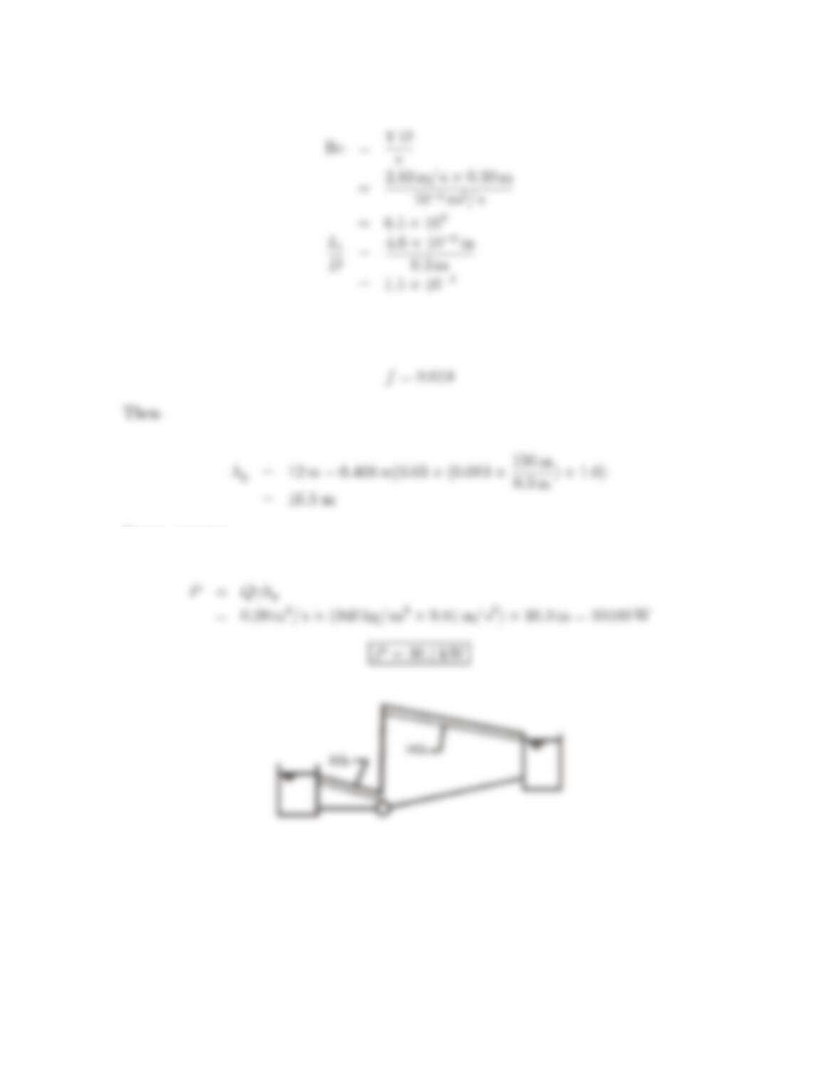
Reynolds number
Resistance coefficient (from the Moody diagram, Fig. 10.14 in EFM10e)
Power equation
111
10.70: PROBLEM DEFINITION
Situation:
A cast iron pipe joins two reservoirs.
D=1.0ft,L=200ft.
z1=150ft,z
2=40ft.
zpipe1 =120ft,z
pipe2 =30ft.
Find:
(a) Calculate the discharge in the pipe.
(b) Sketch the EGL and HGL.
Properties:
From Table 10.4: ks=0.01 in
Water (60oF), Table A.5:
ν=1.22 ×10⁻⁵ft2/s, μ=2.36 ×10⁻⁵N·s/m2,ρ=1.94 slug/m3.
PLAN
Apply the energy equation from the water surface in the upper reservoir to the water
surface in the lower reservoir.
SOLUTION
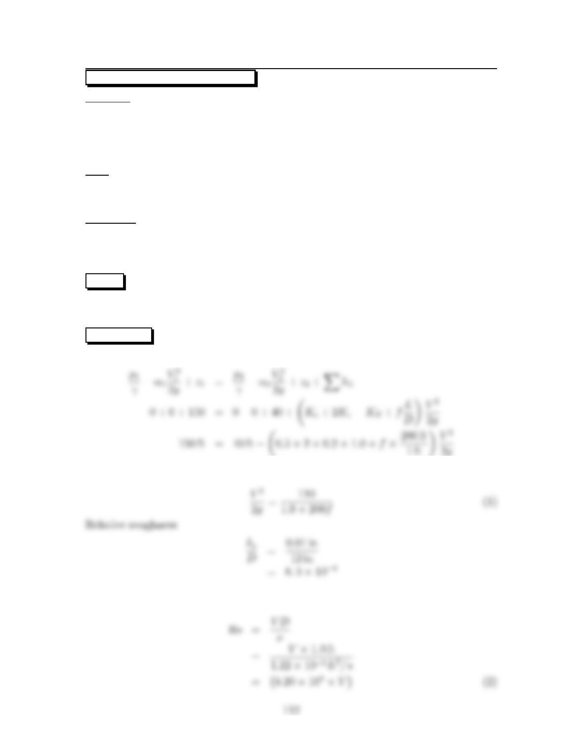
Energy equation
The equation for Vbecomes
Reynolds number
Friction factor (Swamee-Jain Eq. (10.39 in EFM10e))
Solve Eqs. (1) to (3) simultaneously (we applied a computer program, TK Solver)
Flow rate equation
113
10.71: PROBLEM DEFINITION
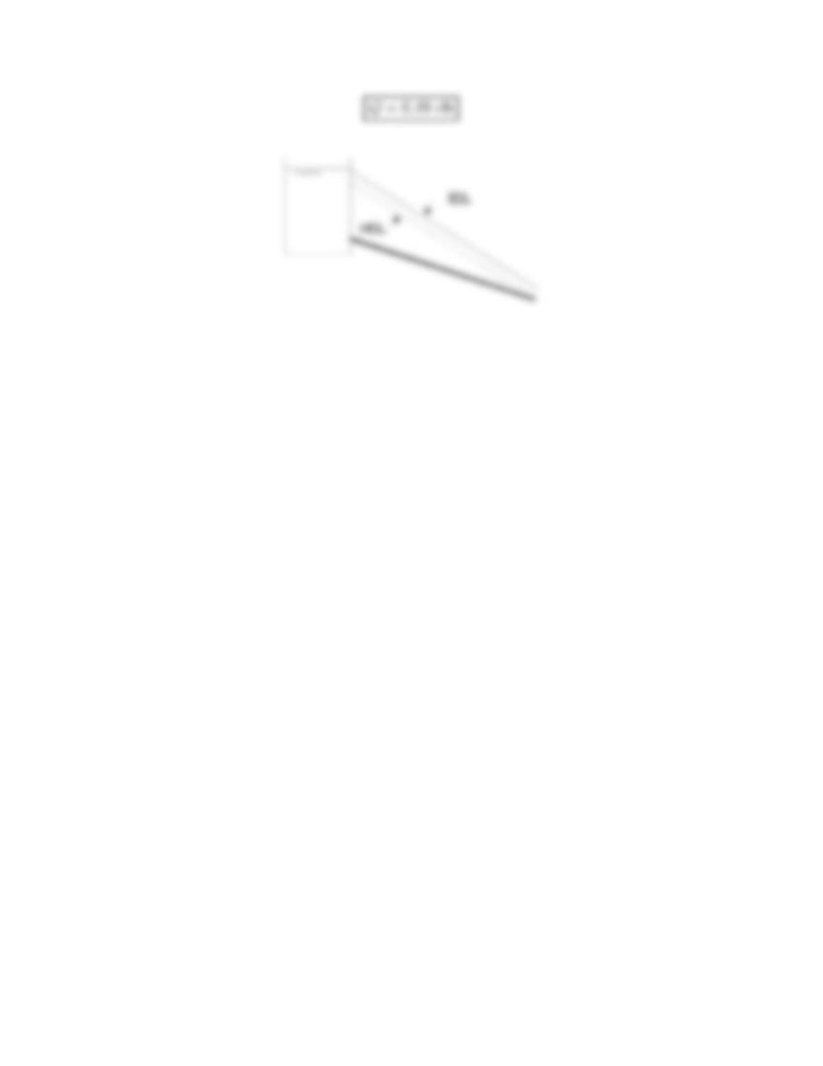
Situation:
Asmallstreamfills a reservoir—water from this reservoir is used to create electrical
power.
Q=2cfs, H=34ft.
hf=3ft,L=87ft.
Sketch:
Find:
Find the minimum diameter for the penstock pipe.
Assumptions:
Neglect minor losses associated with flow through the penstock.
Assume that pipes are available in even sizes—that is, 2 in., 4 in., 6 in., etc.
Assume a smooth, plastic pipe— ks=0.
Assume turbulent flow (check this after the calculation is done).
Properties:
Water (40 ◦F),TableA.5:ν=1.66 ×10⁻⁵ft2/s.
PLAN
Apply the Darcy-Weisbach equation to relate head loss (hf)to pipe diameter. Apply
the Swamee-Jain correlation to relate friction factor (f)to flow velocity. Also, write
equations for the Reynolds number and the flow rate. Solve these four equations
simultaneously to give values of D, V, f, and Re.
SOLUTION
Darcy-Weisbach equation
114
Reynolds number
Re = 289,000
Recommendation
REVIEW
With an 8-inch-diameter pipe, the head loss associated with flow in the pipe will be
less than 10% of the total available head (34 ft). If an engineer selects a pipe that is
larger that 8 inches, then cost goes up.
115
10.72: PROBLEM DEFINITION
Situation:
A pipe runs from a reservoir to an open drain.
zreservoir = 150 ft,zpipe1 =100ft,zpipe2 =60ft.
D=6in,L=100ft,p1=p2=0psi.
Find:
Discharge ¡ft3/s¢.
Properties:
From Table 10.4: ks=4×10⁻⁴ft.
Water (50 ◦F),TableA.5:ν=1.41 ×10⁻⁵ft2/s.
From Table 10.5: Ke=0.5.
PLAN
Apply the energy equation from water surface in reservoir to the outlet.
SOLUTION
Energy equation
Reynolds number
Flow rate equation
117
10.73: PROBLEM DEFINITION
Situation:
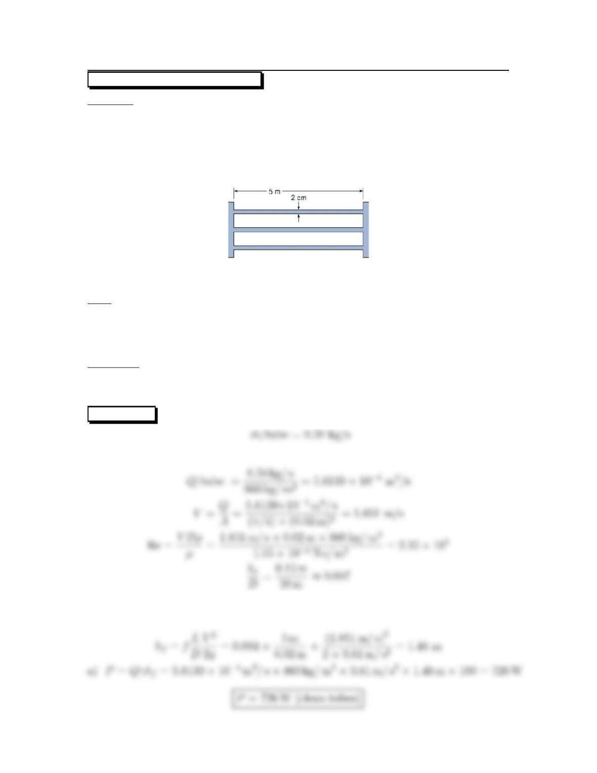
A shell and tube heat exchanger is used in a geothermal power system
Clean fluid inside the tubes; brine outside of the tubes.
100 tubes total. Galvanized iron.
D=2cm,L=5m,˙m=50kg/s.
After continued used, 2 mm of build up, ks=.5mm.
Find:
Power required to operate heat exchanger with:
(a) clean tubes.
(b) scaled tubes.
Properties:
Pipe roughness (galvanized iron), Table 10.4 (EFM10e), ks=0.15 mm.
Given fluid properties (T=200◦C) ρ=860kg/m3,μ=1.35 ×10−4Ns/m2.
SOLUTION
From the Moody diagram, f=0.034.Then
118
Part (b)
119
10.74: PROBLEM DEFINITION
Situation:
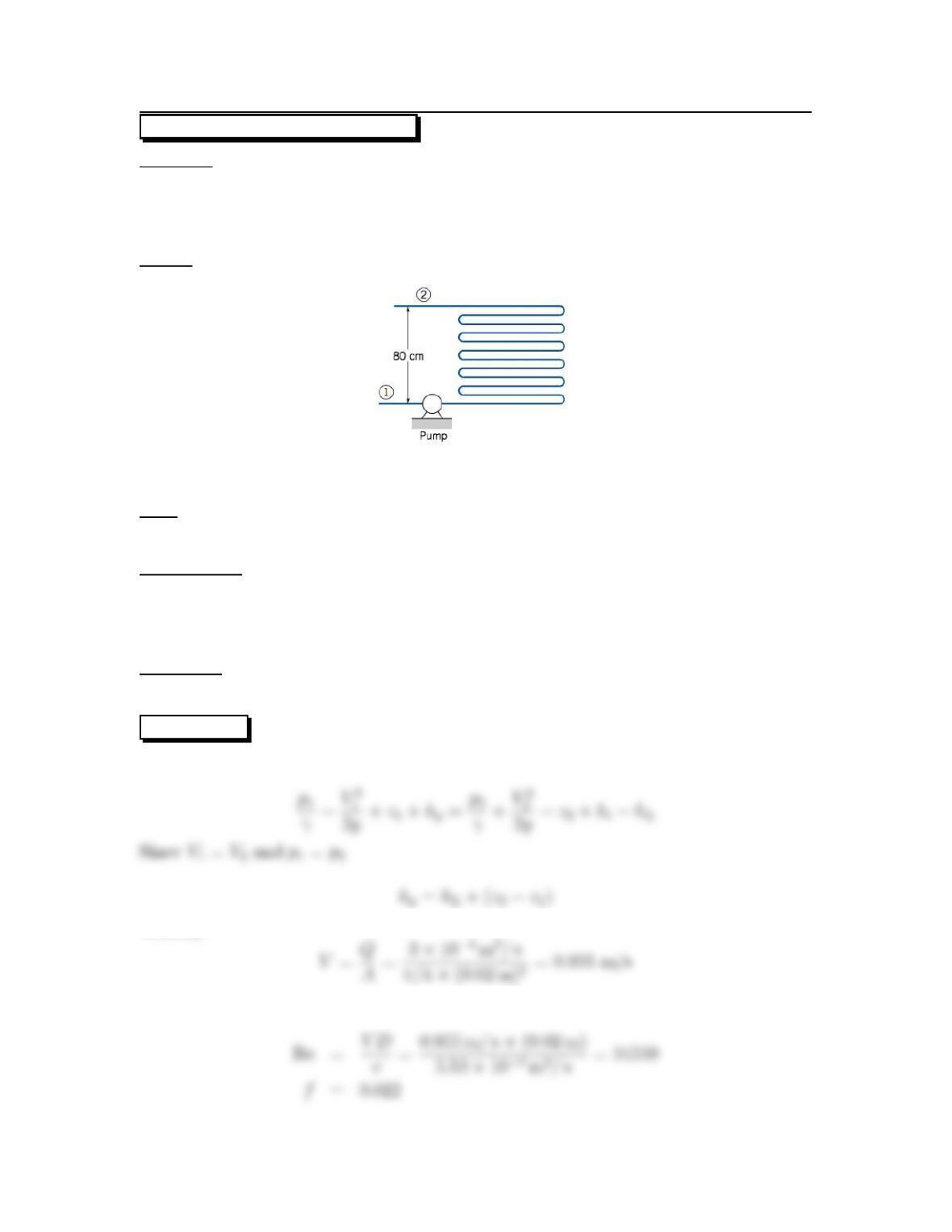
Water flows through a heat exchanger.
L=10m,D=2cm,Q=3.4×10⁻⁴m3/s.
T1=20◦C,T2=80◦C,∆z=0.8m,p
1=p2.
Sketch:
Find:
Pump power required.
Assumptions:
K=2xKforsmoothbendsof90
◦,r/d≈1,K
b≈2∗0.35 = 0.7
Properties can be found at the average temperature in the heat exchanger.
Smooth tubes (ks=0.0m)
Properties:
Water (50 ◦C),TableA.5:ν=5.53 ×10⁻⁷m2/s, ρ=998kg/m3,γ=9693N/m3.
SOLUTION
Energy equation (section 1 at inlet, section 2 at exit)
Velo city
Reynolds number and resistance coefficient
120