PROBLEM 10.24 (Cont.)
()
( )
44
s sat
rad s sat
TT
hTT
εσ
−
=−
()
( )
4 44
2
rad
0.25 623 373 K
h 7.4 W / m K
350 100 K
−
= = ⋅
−
σ
( )( )
2
s
q 231W / m K 0.005 m 350 100 K 907 W / m
′= ⋅× − =
<
2
ss
q q / D 57.8 kW / m
′′ ′
= =
b s fg
m q / h 1.4 kg / h m
′′
= = ⋅
<
( )
3
1/ 2 p, e
v
s fg n
cT
g
qh
C h Pr
ρρ
µσ
∆
−
′′ =
( )
1/ 2
23
3
9.8 m / s 957.9 0.5955 kg / m
58.9 10 N / m
−
−
×
×
3
e
6
4217 J / kg K T
0.0132 2.257 10 J / kg 1.76
⋅ ×∆
×
×× ×
e s sat s
T T T 7.6 K T 107.6 C∆=− = = °
<
The evaporation rate per unit length is
( )
b s fg
m q D h 1.4 kg / h m
′ ′′
= = ⋅
<
Continued …
PROBLEM 10.24 (Cont.)
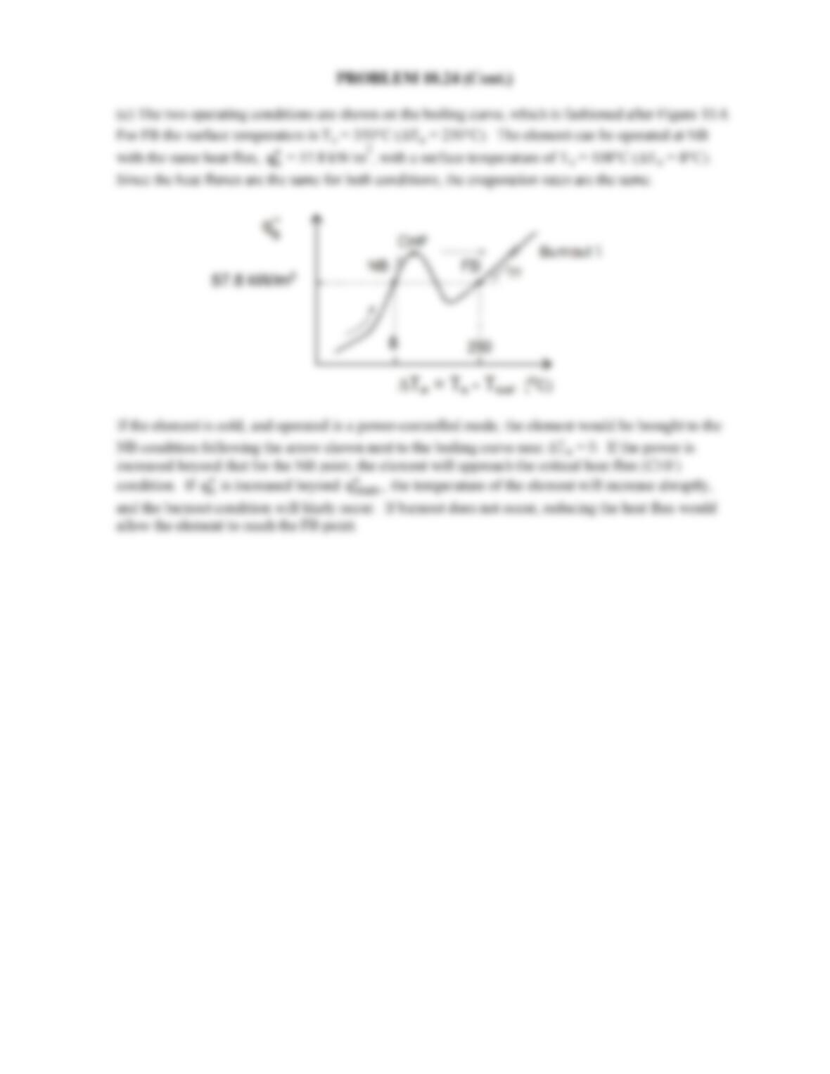
(c) The two operating conditions are shown on the boiling curve, which is fashioned after Figure 10.4.
For FB the surface temperature is Ts = 350°C (∆Te = 250°C). The element can be operated at NB
with the same heat flux,
s
q′′
= 57.8 kW/m2, with a surface temperature of Ts = 108°C (∆Te = 8°C).
Since the heat fluxes are the same for both conditions, the evaporation rates are the same.
If the element is cold, and operated in a power-controlled mode, the element would be brought to the
NB condition following the arrow shown next to the boiling curve near ∆Te = 0. If the power is
increased beyond that for the NB point, the element will approach the critical heat flux (CHF)
condition. If
s
q′′
is increased beyond
max
q,
′′
the temperature of the element will increase abruptly,
and the burnout condition will likely occur. If burnout does not occur, reducing the heat flux would
allow the element to reach the FB point.
57.8 kW/m2
8
57.8 kW/m2
8
57.8 kW/m2
8
57.8 kW/m2
8
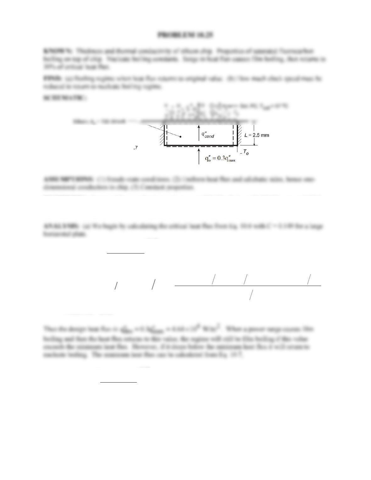
PROBLEM 10.25
KNOWN: Thickness and thermal conductivity of silicon chip. Properties of saturated fluorocarbon
boiling on top of chip. Nucleate boiling constants. Surge in heat flux causes film boiling, then returns to
30% of critical heat flux.
FIND: (a) Boiling regime when heat flux returns to original value. (b) How much clock speed must be
reduced to return to nucleate boiling regime.
SCHEMATIC:
PROPERTIES: Saturated fluorocarbon (given):
p,
c
= 1100 J/kg⋅K, hfg = 84,400 J/kg,
ρ
= 1619.2
kg/m3, ρv = 13.4 kg/m3, σ = 8.1 × 10⁻³ kg/s2,
µ
= 440 × 10-6 kg/m⋅s,
Pr
= 9.01.
( )
( )
()
1/4
v
max fg v 2
v1/4
32 2 3
3
2
3
52
g
q 0.149h
8.1 10 kg s 9.8 m s 1619.2 13.4 kg m
0.149 84,400 J kg 13.4 kg m
13.4 kg m
1.55 10 W/m
−
σ ρ −ρ
′′ = ρ
ρ
×× −
=×××
= ×
( )
( )
1/4
v
min fg v 2
v
g
q 0.09h
σ ρ −ρ
′′ = ρ
ρ +ρ
Continued…
PROBLEM 10.25 (Cont.)
( )
()
1/4
32 2 3
3
min 2
3
32
8.1 10 kg s 9.8 m s 1619.2 13.4 kg m
q 0.09 84,400 J kg 13.4 kg m
1619.2 13.4 kg m
8.46 10 W/m
−
×× −
′′ =×××
+
= ×
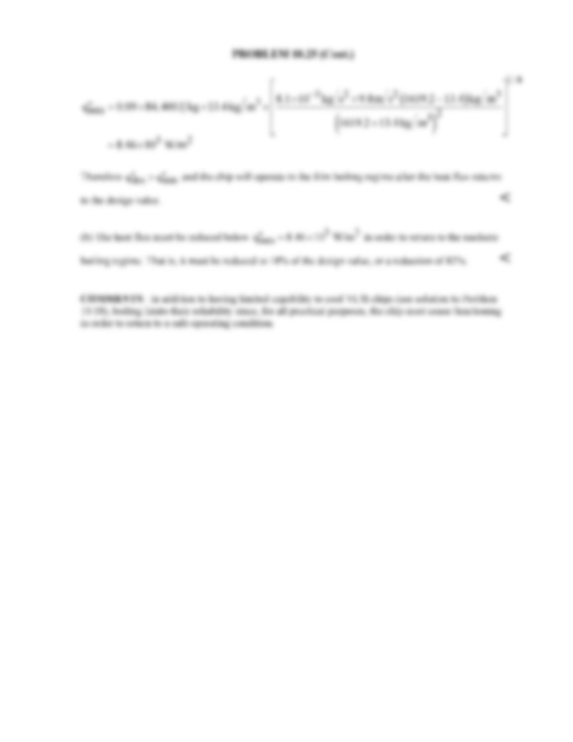
(b) The heat flux must be reduced below
32
min
q 8.46 10 W/m
′′ = ×
in order to return to the nucleate
boiling regime. That is, it must be reduced to 18% of the design value, or a reduction of 82%. <
COMMENTS: In addition to having limited capability to cool VLSI chips (see solution to Problem
10.18), boiling limits their reliability since, for all practical purposes, the chip must cease functioning
in order to return to a safe operating condition.
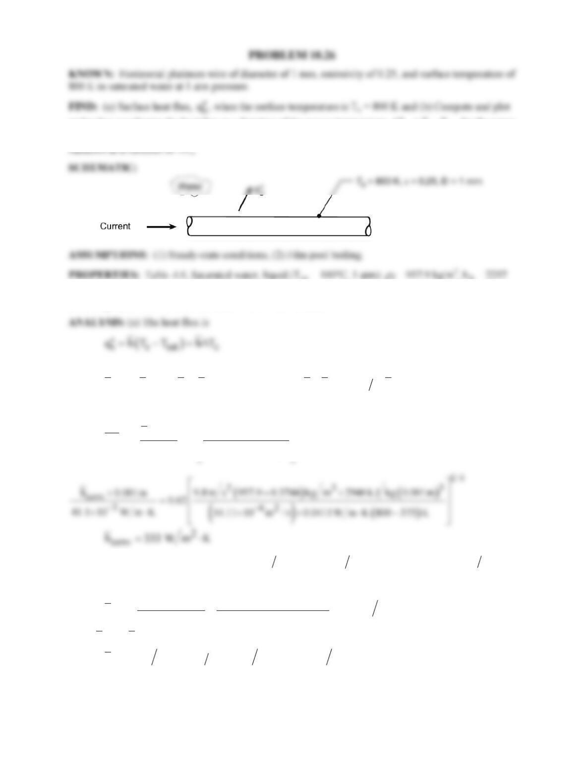
PROBLEM 10.26
KNOWN: Horizontal platinum wire of diameter of 1 mm, emissivity of 0.25, and surface temperature of
800 K in saturated water at 1 atm pressure.
FIND: (a) Surface heat flux,
s
q′′
, when the surface temperature is Ts = 800 K and (b) Compute and plot
on log-log coordinates the heat flux as a function of the excess temperature, ∆Te = Ts – Tsat, for the range
150 ≤ ∆Te ≤ 550 K for emissivities of 0.1, 0.25, and 0.95; separately plot the percentage contribution of
kJ/kg; Table A.4, Water, vapor (Tf = (Ts + Tsat)/2 = (800 + 373)K/2 = 587 K): ρv = 0.3744 kg/m3, cp,v =
2018 J/kg⋅K, νv = 54.11 × 10⁻⁶ m2/s, kv = 41.1 × 10⁻³ W/m⋅K.
where ∆Te = (800 – 373)K = 427 is indicative of film boiling. From Eq. 10.9 or 10.10,
( )
4/3 4/3 1/3
conv rad conv rad
h h h h or h h 3 4 h
−
=+=+
if hrad < hconv. Use Eq. 10.8 with C = 0.62 for a horizontal cylinder,
( )
( )
1/ 4
3
v fg
conv
D
v v v s sat
g hD
hD
Nu C
k kTT
ρρ
ν
′
−
= = −
where
( )
( )
fg fg p,v s sat
h h 0.8c T T 2257 kJ kg 0.8 2018 J kg K 800 373 K 2946 kJ kg.
′= + − = +× ⋅ − =
To
estimate the radiation coefficient, use Eq. 10.11,
()()
( )
4 4 4 44
s sat 2
rad s sat
T T 0.25 800 373 K
h 13.0 W m K .
T T 800 373 K
εσ σ
−−
= = = ⋅
−−
Since
rad conv
hh<
, use the simpler expression,
( )
2 22
h 333 W m K 3 4 13.0 W m K 343 W m K.= ⋅+ ⋅= ⋅
Using the rate equation, find
Continued…
PROBLEM 10.26 (Cont.)
( )
22
s
q 343 W m K 800 373 K 146 kW/m .
′′ = ⋅−=
<
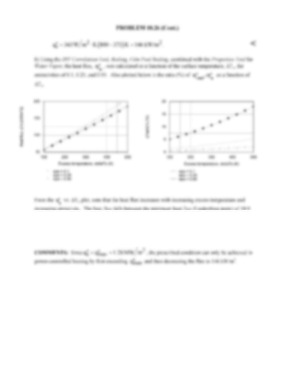
increasing emissivity. The heat flux falls between the minimum heat flux (Liedenfrost point) of 18.9
kW/m2 and the critical heat flux, 1.26 MW/m2 (see Example 10.1 for these values), however for
sufficiently large excess temperature, the film boiling heat flux will exceed the critical heat flux. From
the
/
rad s
qq
′′ ′′
vs. ∆Te plot, the maximum contribution by radiation is around 16%, and occurs at the
maximum surface temperature.
COMMENTS: Since
2
s max
q q 1.26 MW m
′′ ′′
<=
, the prescribed condition can only be achieved in
power-controlled heating by first exceeding
max
q′′
and then decreasing the flux to 146 kW/m2.
/
rad s
qq
′′ ′′
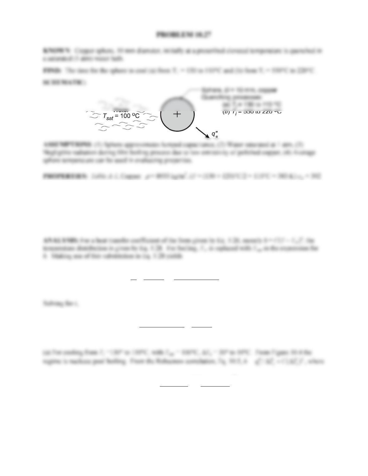
PROBLEM 10.27
KNOWN: Copper sphere, 10 mm diameter, initially at a prescribed elevated temperature is quenched in
a saturated (1 atm) water bath.
FIND: The time for the sphere to cool (a) from Ti = 130 to 110°C and (b) from Ti = 550°C to 220°C .
SCHEMATIC:
J/kg ⋅ K; (T = (550 + 220)°C/2 = 385°C = 658 K, cp = 422 J/kg ⋅ K. Table A.11, Copper (polished) :
ε
=
0.04, typical value; Table A.6, Water (T = 373 K),
ρ
l = 1/vf = 958 kg/m3,
ρ
v = 1/vg = 0.596 kg/m3, hfg =
2257 kJ/kg, cp,l = 4.217 kJ/kg ⋅ K, µl = 279 × 10-6 N ⋅ s/m2,
σ
= 58.9 × 10⁻³ N/m, Prl = 1.76; Table A.4,
Water (Tf = (Ts + Tsat)/2 515 K),
ρ
v = 1/vg = 0.428 kg/m3, cp,v = 1.989 kJ/kg ⋅ K,
ν
v =4.13 × 10⁻⁵ m2/s,
kv = 0.0351 W/m ⋅ K.
1/
, sat
sat
sat
()
1
n
n
sc i
ii
nCA T T
TT t
T T Vc
θ
θρ
−
−
−
= = +
−
(1)
sat
sat
, sat
1
()
n
n
i
sc i
Vc T T
tTT
nCA T T
ρ
−
−
= −
−
−
(2)
3
1/2
,
,
() pl
lv
l fg m
s f fg l
c
g
Ch C h Pr
ρρ
µσ
−
=
Note that exponent m has been used instead of n, to distinguish from the n exponent in Eqs. (1) and (2).
From Table 10.1, Cs,f = 0.0128, m = 1.0, thus
Continued…
PROBLEM 10.27 (Cont.)
1/ 2
23 3
62 3
3
3
23
3 1.0
9.8 m/s (958 kg/m 0.596 kg/m )
279 10 N s/m 2257 10 J/kg 58.9 10 N/m
4217 J/kg K
143 W/m K
0.0128 2257 10 J/kg 1.76
C−
−
−
=× ⋅× × ×
×
⋅
×=⋅
×× ×
2
3
23 2
8933 kg/m 395 J/kg K 0.010 m/6 110 C 100 C 1 0.18 s
130 C 100 C
2 143 W/m K (130 C 100 C)
t
−
× ⋅ × °− °
= −=
°− °
× ⋅ × °− °
<
1/4
3
()
0.67 l v fg
v
vv
g hD
k
CDk
ρρ
ν
′
−
=
In this expression, fg
h′
is a function of temperature,
, sat
0.80 ( )
fg fg p v
h h c TT
′=+−
. However, since Eqs.
(1) and (2) are only valid for C = const., we evaluate
fg
h′
at the average temperature, T = (550 + 220)°C/2
= 385°C. This is a reasonable approximation since the temperature-dependent second term is
substantially smaller than hfg. Thus,
, sat
0.80 ( ) 2257 kJ/kg 0.80 1.989 kJ/kg K (385 100) C 2710 kJ/kg
fg fg p v
h h c TT
′= + − = + × ⋅ × − °=
1/ 4
23 3 3 3
52
2 3/4
0.0351 W/m K 9.8 m/s (958 kg/m 0.428 kg/m ) 2710 10 J/kg (0.010 m)
0.67 0.010 m 4.13 10 m /s 0.0351 W/m K
C−
⋅ − ×× ×
=
×× ⋅
1/4
3
2 3/4 1/4
8933 kg/m 422 J/kg K 0.010 m/6 220 C 100 C 1 38.0 s
550 C 100 C
(1 / 4) 856 W/m K (550 C 100 C)
t−
× ⋅ × °− °
= −=
°− °
− × ⋅ × °− °
<
COMMENTS: Comparing the elapsed times for the two processes, the nucleate pool boiling process
cools 20°C in 0.18s (110°C/s) vs. 330°C in 38.0s (8.7°C/s) for the film pool boiling process.
PROBLEM 10.28
KNOWN: Saturated water at 1 atm is heated in cross flow with velocities 0 – 2 m/s over a 2 mm-
diameter tube.
FIND: Plot the critical heat flux as a function of water velocity; identify the pool boiling and
transition regions between the low and high velocity ranges.
SCHEMATIC:
PROPERTIES: Table A-6, Water (1 atm): Tsat = 100°C,
ρ
= 957.9 kg/m3, ρv = 0.5955 kg/m3, hfg
= 2257 kJ/kg, σ = 58.9 × 10⁻³ N/m.
1/3
v fg
max 2
v
h4
q1 V
VD
ρσ
ρ
′′
= +
1/3
3
3
max 3 32
1 kg J 4 58.9 10 N / m
q 0.5955 2257 10 1 V
kg
m 0.5955kg / m V 0.002m
−
××
′′
= ×× +
5 6 1/3
q 4.2782 10 V 2.493 10 V .
′′ = ×+×
3/4
3
max 3
1 kg J 1 957.9
q 0.5955 2257 10 kg 169 0.5955
m
′′
= ×× +
1/3
1/ 2 3
32
1 957.9 58.9 10 N / m V
19.2 0.5955 0.5955 kg / m V 0.002m
−
×
5 6 1/3
max
q 6.4299 10 V 3.280 10 V
′′ = ×+×
Continued …
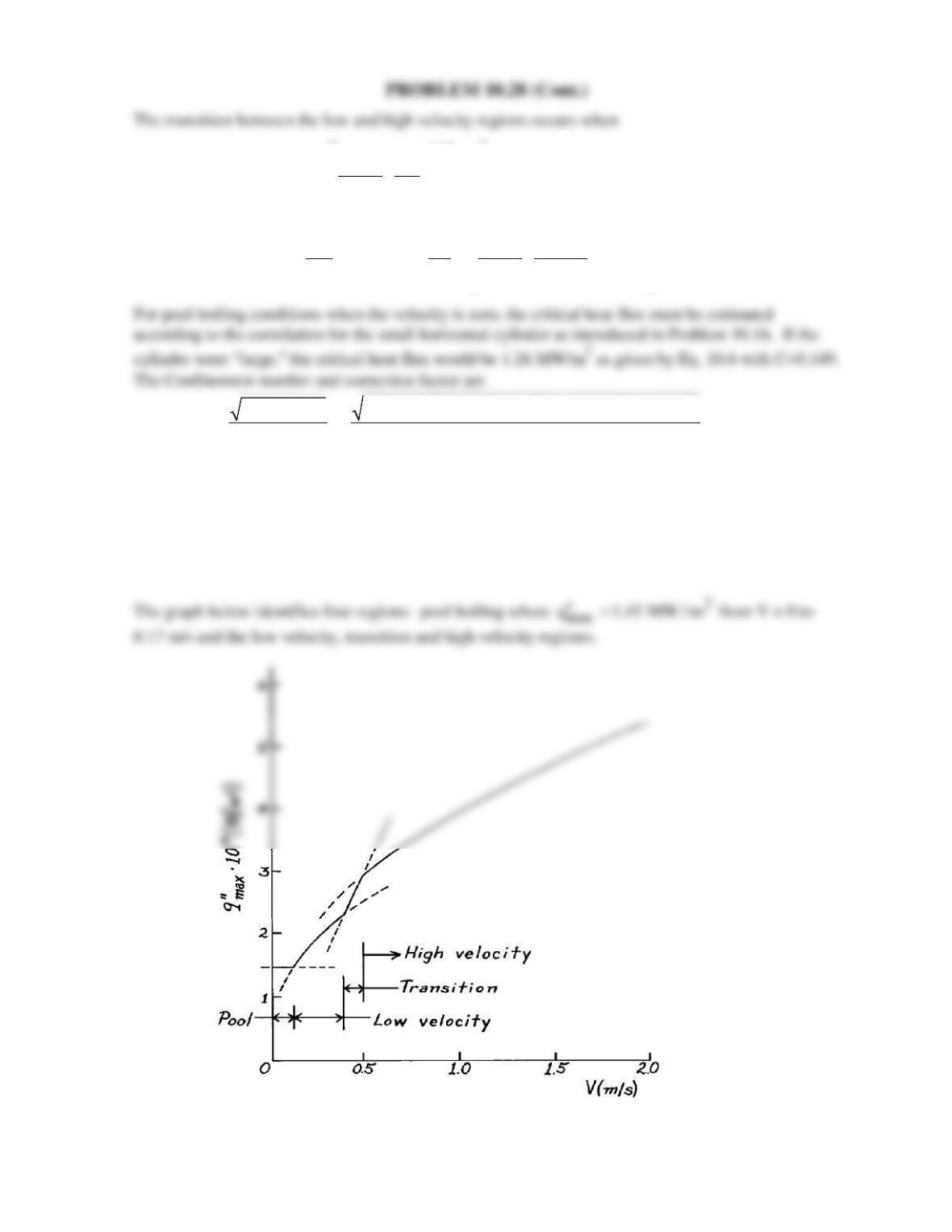
PROBLEM 10.28 (Cont.)
The transition between the low and high velocity regions occurs when
1/ 2
max v fg v
0.275
q hV 1
ρ
ρρ
′′ = +
1/ 2
36
max 3
kg J 0.275 957.9
q 0.5955 2257 10 V 1 6.0627 10 V.
kg 0.5955
m
′′
= × × += ×
(3)
-3 2 3
v
σ/g(ρ – ρ ) 58.9 × 10 N/m/9.8 m/s (957.9 – 0.5955) kg/m
Co= = = 2.51
r 0.001 m
F = 0.89 + 2.27 exp (-3.44
1/2
Co
−
) = 1.15
and the critical heat flux for the “small” 2 mm cylinder is
)
22
max pool
q 1.15 1.26 MW / m 1.45 MW / m .
′′ =×=
1.451.45
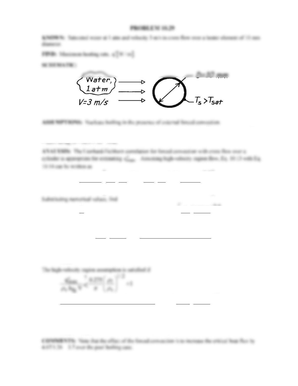
PROBLEM 10.29
KNOWN: Saturated water at 1 atm and velocity 3 m/s in cross flow over a heater element of 10 mm
diameter.
FIND: Maximum heating rate,
q W/m .
′
SCHEMATIC:
PROPERTIES: Table A-6, Water (1 atm): Tsat = 100°C,
ρ
= 957.9 kg/m3, ρv = 0.5955 kg/m3, hfg
max
1/3
3/4 1/2
v fg
max 2
vv
v
hV 11
q.
169 19.2 VD
ρρ ρσ
ρ ρ
ρ
′′
= +
3/4
33
max
1 1 957.9
q 0.5955kg / m 2257 10 J / kg 3m / s 169 0.5955
′′
= ×× × +
( )
1/3
1/ 2 3
2
3
1 957.9 58.9 10 N / m
19.2 0.5955 0.5955kg / m 3m / s 0.01m
−
×
2
max
q 4.67 MW / m .
′′ =
1/ 2
62 ?
33
4.67 10 W / m 0.275 957.9
1.17 1 4.51.
0.5955
0.5955kg / m 2257 10 J / kg 3m / s
×
= +=
×× × <
The inequality is satisfied. Using the
max
q′′
estimate, the maximum heating rate is
( )
2
max max
q q D 4.67 MW / m 0.01m 147 kW / m.
′ ′′
= ⋅= × =
<
COMMENTS: Note that the effect of the forced convection is to increase the critical heat flux by
4.67/1.26 = 3.7 over the pool boiling case.
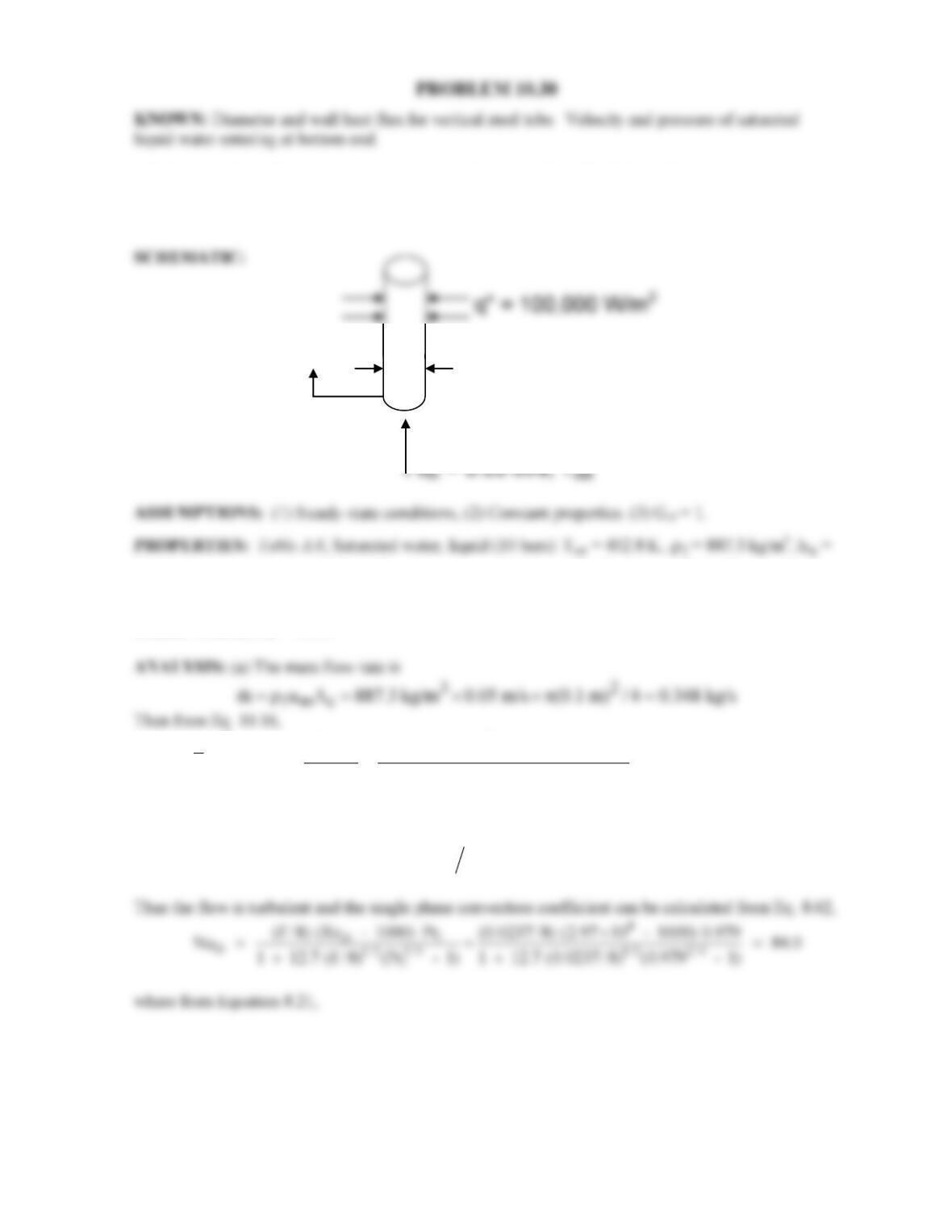
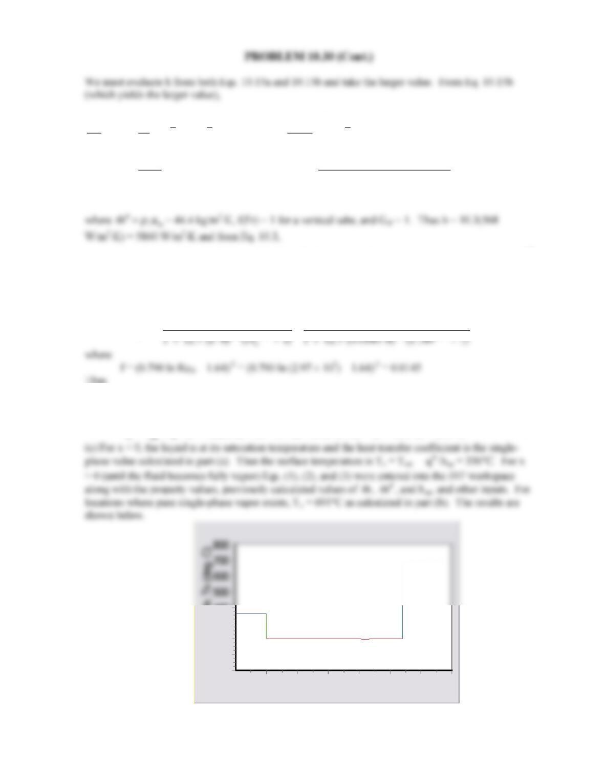
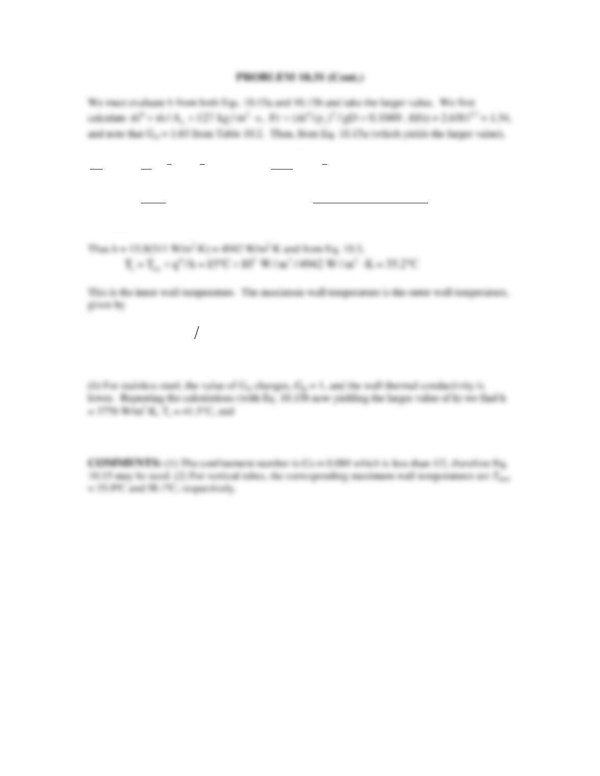
PROBLEM 10.30
KNOWN: Diameter and wall heat flux for vertical steel tube. Velocity and pressure of saturated
liquid water entering at bottom end.
FIND: (a) Tube wall temperature and water quality at x = 15 m. (b) Tube wall temperature at location
where single–phase vapor flow exists at mean temperature Tsat. (c) Plot tube wall temperature for –5 m
≤ x ≤ 30 m.
2014 kJ/kg,
µ
=149.4 × 10⁻⁶ N⋅s/m2,
/ν=µ ρ=
1.684 × 10⁻⁷ m2/s,
k
= 0.6766 W/m⋅K,
Pr
=
0.979. Table A.4, water vapor (T = 452.8 K):
v
ρ
= 5.094 kg/m3,
v
µ
= 14.95 × 10⁻⁶ N⋅s/m2, kv =
0.03353 W/m⋅K, Prv = 1.149.
s
2
Dx
6
fg
q100,000 W/m 0.1 m 15 m
X(x 15 m) 0.672
mh 0.348 kg/s 2.014 10 J/kg
′′ ×× ×
= = = =
××
(1) <
To find the wall temperature, we must first find the convection coefficient from Eq. 10.15. The
Reynolds number is
72 4
Dm
Re u D / 0.05 m/s 0.1 m 1.684 10 m / s 2.97 10
−
= ν= × × = ×
f = (0.790 ln ReD – 1.64)-2 = (0.790 ln (2.97 × 10⁴) – 1.64)-2 = 0.0237
Thus
2
sp D
h Nu k / D 84.0 0.6766 W / m K / 0.1 m 568 W / m K= =× ⋅= ⋅
Continued…
D = 0.1 m
x
Water
PROBLEM 10.30 (Cont.)
We must evaluate h from both Eqs. 10.15a and 10.15b and take the larger value. From Eq. 10.15b
(which yields the larger value),
0.7
0.45
0.72 0.08 0.8
ssf
sp v fg
0.45 52
0.72 0.08
q
h1.136 X (1 X) f (Fr) 667.2 (1 X) G (2)
h mh
887.3 10 W / m
1.136 0.672 (1 0.672) 1 667.2
5.094 44.4 kg
′′
ρ
= −+ −
′′
ρ
= − ×+
0.7
0.8
26
(1 0.672) 1
/ m s 2.014 10 J / kg
10.3
−×
⋅× ×
=
52 2
s sat
T T q / h 452.8 K 10 W / m / 5860 W / m K 470 K 197 C
′′
= + = + ⋅= = °
(3) <
(b) The mass flow rate is unchanged, but the viscosity is now that of the vapor, therefore,
62 5
Dv
Re 4m / D 4 0.348 kg / s / 0.1 m 14.95 10 N s / m 2.97 10
−
= µ = × × × × ⋅ = ×
And once again from Eqs. 8.62 and 8.21,
5
Dv
D1/2 2/3 1/2 2/3
(f /8) (Re – 1000) Pr (0.0145/8) (2.97 10 – 1000) 1.149
Nu 584
×
= = =
Thus
2
Dv
h Nu k / D 584 0.03353 W / m K / 0.1 m 196 W / m K= =× ⋅= ⋅
and
52 2
T T q / h 452.8 K 10 W / m /196 W / m K 964 K 691 C
′′
= + = + ⋅= = °
<
x (m)
302520151050
Surface temperature, Ts (deg. C)
400
300
200
100
0
Continued…

PROBLEM 10.30 (Cont.)
COMMENTS: (1) During pool boiling, we are concerned about approaching the critical heat flux.
During forced convection boiling, an analogous situation exists whereby, once the liquid phase is
entirely consumed, surface temperatures rise very rapidly, potentially melting the tube material. In
applications where production of superheated steam is desired, such as in a Rankine power cycle,
precautions must be made to ensure the tube material will survive the high temperatures in regions
associated with pure vapor conditions. (2) Surface temperatures at negative x values will be slightly
less than shown for the pure liquid flow. This is because the fluid quality is averaged across the tube
radius and, for x < 0, fluid near the centerline of the tube will consist of subcooled liquid while
superheated vapor exists near the tube wall. This situation can yield values of
X
equal to zero, even
though two-phase flow exists in the fluid, increasing the convection coefficient. Similarly, the average
quality reaches a value of unity at x = 22.3 m. Just beyond this location, the flow consists mainly of
vapor, but a subcooled liquid mist can exist near the core of the flow, suppressing tube surface
temperatures relative to those indicated just beyond x = 22.3 m. (3) The quality reaches a value of 0.8
at x = 17.8 m and Equation 10.15 is no longer applicable. The surface temperatures reported in the
range 17.8 m ≤ x ≤ 22.3 m will be less accurate than for those further upstream. (4) The pressure will
decrease with increasing x due to friction losses. Prediction of pressure drops in flow boiling is
difficult.
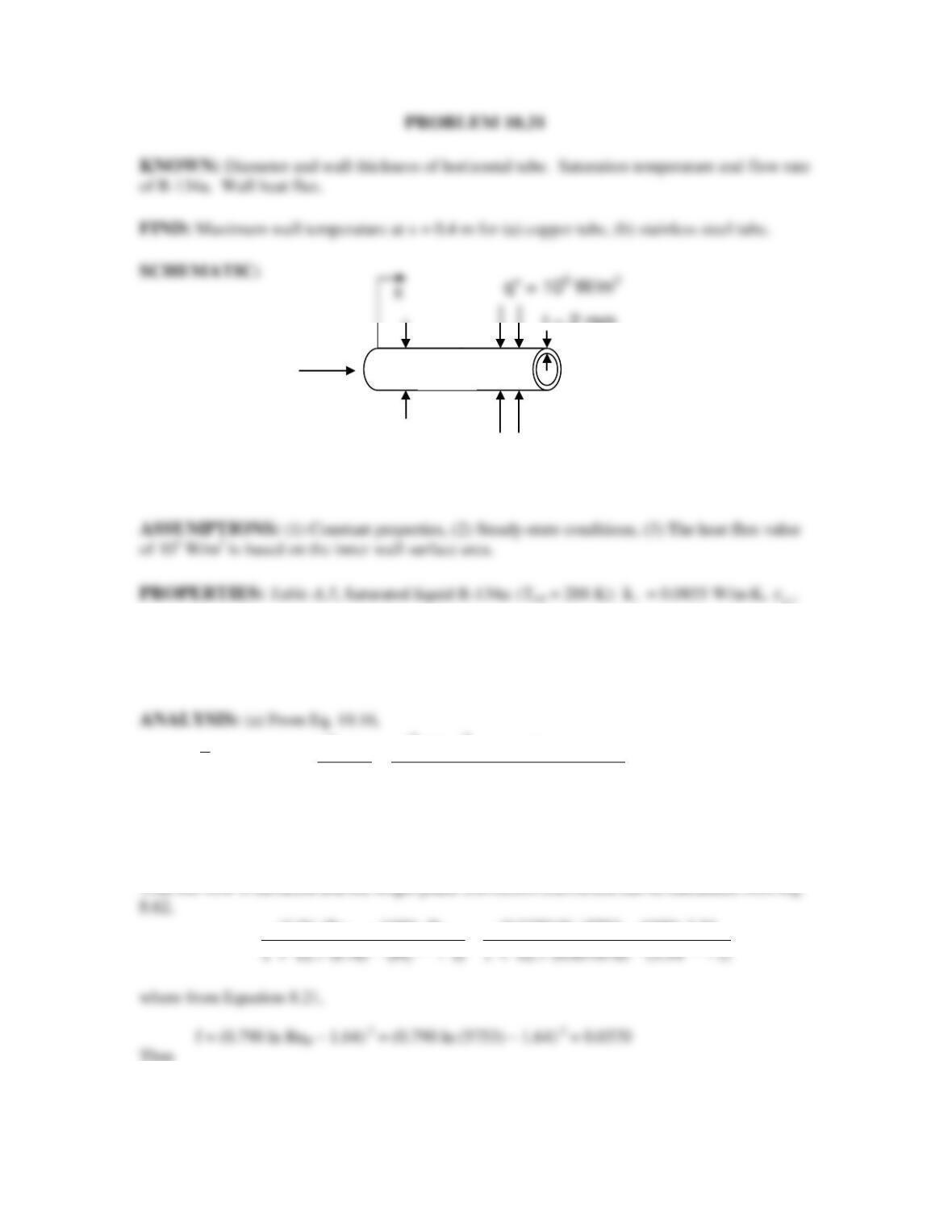
PROBLEM 10.31
KNOWN: Diameter and wall thickness of horizontal tube. Saturation temperature and flow rate
of R-134a. Wall heat flux.
FIND: Maximum wall temperature at x = 0.4 m for (a) copper tube, (b) stainless steel tube.
SCHEMATIC:
= 1387 J/kg⋅K,
µ
= 2.213 × 10⁻⁴ N⋅s/m2,
Pr
= 3.54,
ρ
= 1243.8 kg/m3, hfg = 186.6 kJ/kg.
Saturated vapor R-134a (given):
v
ρ
= 23.75 kg/m3. Table A.1, Pure copper (T 300 K): kw =
401 W/m⋅K. Table A.1, AISI 316 SS (T 300 K): kw = 13.4 W/m⋅K.
s
52
Dx
3
fg
q10 W/m 0.01 m 0.4 m
X(x 0.4 m) 0.673
mh 0.01 kg/s 186.6 10 J/kg
′′ ×× ×
= = = =
××
To find the wall temperature, we must first find the convection coefficient from Eq. 10.15. The
Reynolds number is
42
D
Re 4m / D 4 0.01 kg / s / 0.01 m 2.213 10 N s / m 5753
−
= µ = × × × × ⋅ =
D
D1/2 2/3 1/2 2/3
(f /8) (Re – 1000) Pr (0.0370 / 8) (5753 – 1000) 3.54
Nu 36.3
= = =
Thus
2
sp D
h Nu k / D 36.3 0.0855 W / m K / 0.01 m 311 W / m K= =× ⋅= ⋅
Continued…
x
q” = 105 W/m2
R-134a
m
= 0.01 kg/s
Tsat = 15°C
D = 0.01 m
t = 2 mm
PROBLEM 10.31 (Cont.)
We must evaluate h from both Eqs. 10.15a and 10.15b and take the larger value. We first
calculate
2
c
m m / A 127 kg / m s
′′ = = ⋅
,
2
Fr (m / ) / gD 0.1069
′′
=ρ=
, f(Fr) = 2.63Fr0.3 = 1.34,
and note that Gsf = 1.63 from Table 10.2. Then, from Eq. 10.15a (which yields the larger value),
0.7
0.1
0.16 0.64 0.8
ssf
sp v fg
0.1 52
0.16 0.64
2
hq
0.6683 X (1 X) f (Fr) 1058 (1 X) G
h mh
1243.8 10 W / m
0.6683 0.673 (1 0.673) 1.34 1058
23.75 127 kg / m s 186
′′
ρ
= −+ −
′′
ρ
= − ×+
⋅×
0.7
0.8
3
(1 0.673) 1.63
.6 10 J / kg
15.9
−×
×
=
52
s.o s i o i w
T T q r ln(r / r ) k 35.2 C 10 W / m 0.005 m ln(0.007 / 0.005) / 401 W / m K
′′
= + = °+ × ⋅
s,o
T 35.6 C= °
<
s,o
T 54.0 C= °
<
COMMENTS: (1) The confinement number is Co = 0.089 which is less than 1/2, therefore Eq.
10.15 may be used. (2) For vertical tubes, the corresponding maximum wall temperatures are Tmax
= 35.9ºC and 58.1ºC, respectively.
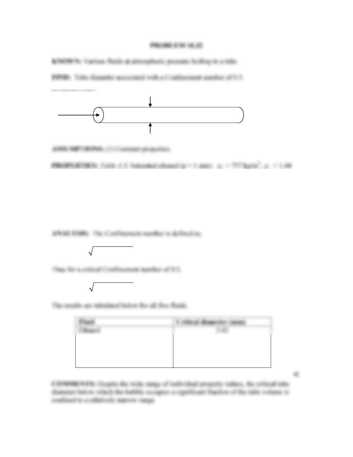
PROBLEM 10.32
KNOWN: Various fluids at atmospheric pressure boiling in a tube.
FIND: Tube diameter associated with a Confinement number of 0.5.
SCHEMATIC:
attached
v
kg/m3, σ = 17.7 × 10⁻³ N/m. Saturated mercury (p = 1 atm):
ρ
= 12,740 kg/m3,
v
ρ
=
3.90 kg/m3, σ = 417 × 10-3 N/m. Saturated R-134a (p = 1 atm):
ρ
= 1377 kg/m3,
v
ρ
=
5.26 kg/m3, σ = 15.4 × 10⁻³ N/m. Saturated dielectric fluid, given in Problem 10.18 (p =
1 atm):
ρ
= 1619.2 kg/m3,
v
ρ
= 13.4 kg/m3, σ = 8.1 × 10⁻³ N/m. Table A.6, Saturated
water (p = 1 atm):
ρ
= 989 kg/m3,
v
ρ
= 0.595 kg/m3, σ = 58.9 × 10⁻³ N/m.
v
Co /[g( )] / D= σ ρ −ρ
v
D 2 /[g( )]= σ ρ −ρ
Ethanol
3.03
Mercury
3.65
Water
4.93
R-134a
2.14
Dielectric fluid
1.43
<
COMMENTS: Despite the wide range of individual property values, the critical tube
diameter below which the bubble occupies a significant fraction of the tube volume is
confined to a relatively narrow range.
Fluid
D
ρ
ρ
PROBLEM 10.33
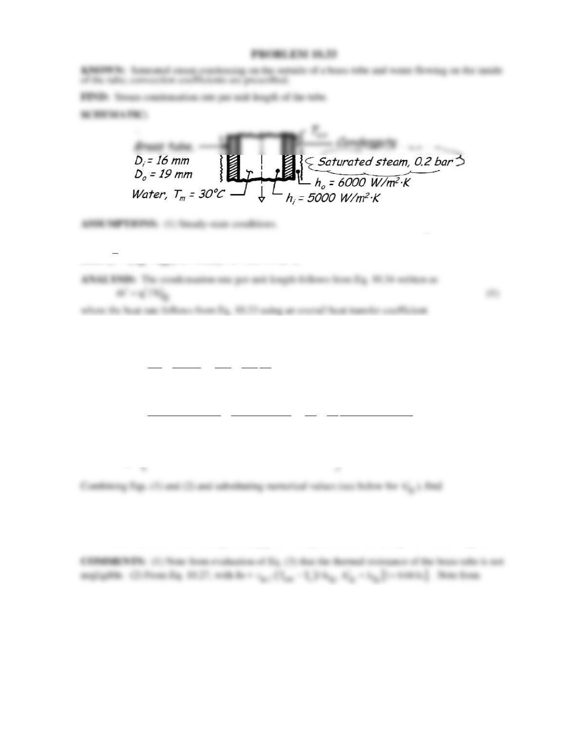
KNOWN: Saturated steam condensing on the outside of a brass tube and water flowing on the inside
of the tube; convection coefficients are prescribed.
FIND: Steam condensation rate per unit length of the tube.
SCHEMATIC:
PROPERTIES: Table A-6, Water, vapor (0.2 bar): Tsat 333 K, hfg = 2358 × 103 J/kg; Table A-1,
Brass
()
()
T T T / 2 300K : k 110 W / m K=+ = ⋅
()
oosatm
qU DT T
′=⋅ − (2)
and from Eq. 3.36,
1
ooo
ooiii
D/2 D D
11
Un
hkDDh
−
=+ +
(3)
1
o22
1 0.0095m 19 19 1
Un
110 W / m K 16 16
6000 W / m K 5000 W / m K
−
=+ +
⋅
⋅⋅
1
6662 2
o
U 166.7 10 14.84 10 237.5 10 W / m K 2390 W / m K.
−
−−−
=×+×+× ⋅= ⋅
()
oosat m fg
mUDT T/h
′′
=−
()( )
233
m 2390 W / m K 0.019m 333 303 K / 2410 10 J / kg 1.78 10 kg / s.
−
′=⋅ −×=×
<
expression for Uo, that the internal resistance is the largest. Hence, estimate Ts,o To – (Ro/R) (To –
Tm) 316K. Hence,
()
33
fg
h 2358 10 J / kg 1 0.68 4182 J / kg K 333 316 K / 2358 10 J / kg
′× +× ⋅ − ×
fg
h 2410 kJ / kg
′=
where
p
,
c for water (liquid) is evaluated at Tf = (Ts,o + To)/2 325K.
PROBLEM 10.34
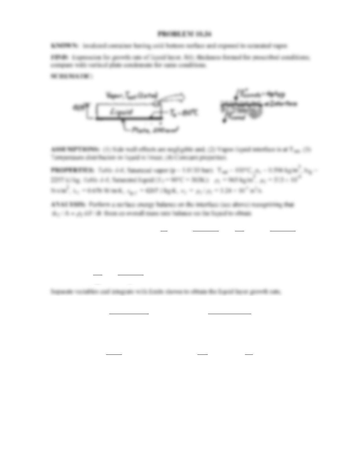
KNOWN: Insulated container having cold bottom surface and exposed to saturated vapor.
FIND: Expression for growth rate of liquid layer, d(t); thickness formed for prescribed conditions;
compare with vertical plate condensate for same conditions.
SCHEMATIC:
sat s sat s
in out conds cond fg fg
TT TT
md
EE q q hk hk 0
A dt
d
ρ
dd
−−
′′ ′′ ′′ ′′
−=−=−=−=
(1)
where
conds
q′′
is the condensation heat flux and
cond
q′′
is the conduction heat flux into the liquid layer
of thickness d with linear temperature distribution. Eq. (1) can be rewritten as
sat s
fg
TT
d
hk .
dt
d
ρd
−
=
( ) ( )
1/2
tsat s sat s
00fg fg
kT T 2kT T
d dt or t .
hh
d
dd d
ρρ
−−
= =
∫∫
(2) <
For the prescribed conditions, the liquid layer thickness and condensate formed in one hour are
( ) ( )
1/2
3
3
W kg J
1h 2 0.676 100 80 C 3600s / 965 2257 10 6.69 mm
m K kg
m
d
= × − °× × × =
⋅
<
( )
3 62 3 3
m 1h A 965kg / m 200 10 m 6.69 10 m 1.29 10 kg.
ρd
− −−
= = ×× × × = ×
<
Continued …
PROBLEM 10.34 (Cont.)
The condensate formed on a vertical plate of length
2
L 200 mm 0.0141 m= =
with the same
conditions follows from Eq. 10.34,
( )
vp L sat s fg
m m t h A T T t/h
′
= ⋅= − ⋅
where
fg L
h and h
′
follow from Eqs. 10.27 and one of Eqs. 10.43 – 10.45, respectively, with P given
by Eq. 10.42.
( )
( )
fg fg fg p, fg
h h 1 0.68Ja h 1 0.68c T / h
′=+=+ ∆
( )
33
fg
J
h 2257 10 J / kg 1 0.68 4207 100 80 C / 2257 10 J / kg 2314kJ / kg
kg K
′= × + × −° × =
⋅
sat s
2 1/3
fg
1/3
-6 2 3 -7 2 2 2
kL(T T )
Ph ( / g)
0.676 W/m K × 0.0141 m(100 – 80)°C
= 11.9
313×10 N s/m × 2314 × 10 J/kg × (3.24 × 10 m /s) /9.8 m/s
ν
−
=′
µ
⋅=
⋅
Since P < 15.8, Eq. 10.43 gives
1/4 1/4 2
L2 1/ 3 1/3
-7 2 2 2
k 0.676 W/m K
h 0.943P 0.943 11.9 15,560 W / m K
( / g) (3.24 × 10 m /s) /9.8 m/s
−−
⋅
= = ×= ⋅
ν
Hence,
( )
2 62 3
vp
m 15,560 W / m K 200 10 m 100 80 C 3600s / 2314 10 J / kg
−
= ⋅ × × − °× ×
2
vp
m 9.7 10 kg.
−
= ×
<
COMMENTS: Note that the condensate formed by the vertical plate is almost two orders of
magnitude larger. For the vertical plate the rate of condensate formation is constant. For the
container bottom surface, the rate decreases with increasing time since the conduction resistance
increases as the liquid layer thickness increases.