PROBLEM 10.47 (Cont.)
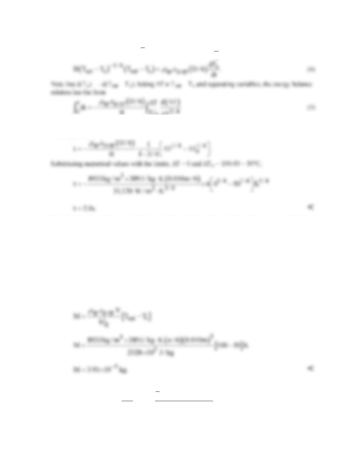
Substitute Eq. (3) into Eq. (1) for
D
h
and recognize
32
ss
1
V / A D / D D / 6,
6
ππ
= =
o
where the limits of integration have been identified, with
o sat i
TT T∆= −
and Ti = Ts(0). Performing
the integration, find
To determine the total amount of condensate formed during this period, perform an energy balance on
a time interval basis,
in out final initial
E E EE E− =∆= −
(
]
in sp p,sp final initial
E c VT T
ρ
= −
(6)
where Tfinal = Tsat and Tinitial = Ti = Ts(0). Recognize that
in fg
E Mh
′
=
(7)
where M is the total mass of vapor that condenses. Combining Eqs. (6) and (7),
COMMENTS: The total amount of condensate could have been evaluated from the integral,
( )
tt t
D s sat s
00 0
fg fg
h A T T dt
q
M m dt dt
hh
−
= = =
′′
∫∫ ∫
giving the same result, but with more effort.
PROBLEM 10.48
KNOWN: Saturation temperature and inlet flow rate of refrigerant. Diameter, length, and
temperature of tube.
FIND: Rate of condensation and outlet flow rate.
SCHEMATIC:
Ts = 290 K
ASSUMPTIONS: (1) Negligible concentration of noncondensable gases in vapor.
PROPERTIES: Given, R-12, saturated vapor (Tsat = 310 K): ρv = 50.1 kg/m3, hfg = 160 kJ/kg, mv
ANALYSIS: For R-12: The Reynolds number associated with the inlet vapor flow is
v,i v,i v
Re 4 m / D= πm
72
0.04 kg / s / 0.03 m 150 10 N s / m 28, 290 35, 000.
π
−
= × ×× ⋅ = <
Hence, the
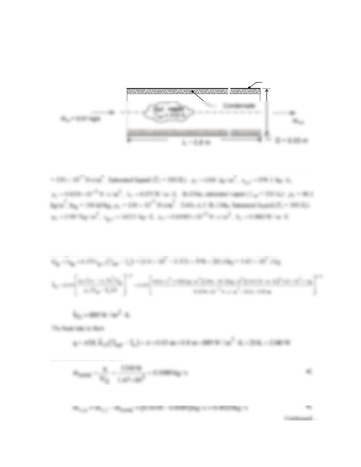
average convection coefficient may be obtained from Eq. 10.46 with C = 0.555, where
and the condensation rate is
The flow rate of vapor leaving the tube is then
PROBLEM 10.48 (Cont.)
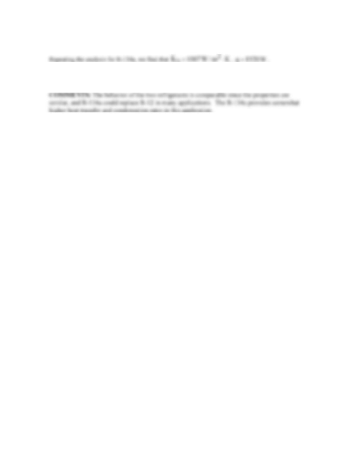
D
cond
m 0.0086 kg / s=
, and
v,o
m 0.0014 kg / s=
. <
PROBLEM 10.49
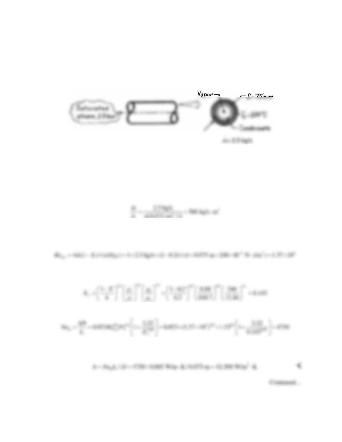
KNOWN: Saturated steam condensing on the inside of a horizontal pipe.
FIND: Heat transfer coefficient and the condensation rate per unit length of the pipe.
SCHEMATIC:
ASSUMPTIONS: (1) Film condensation with low vapor velocities.
PROPERTIES: Table A-6, Saturated water vapor (1.5 bar): Tsat ≈ 385K, ρv = 0.88 kg/m3, hfg =
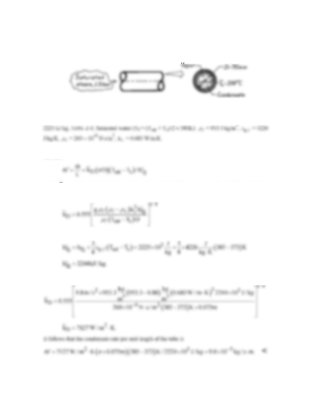
ANALYSIS: The condensation rate per unit length follows from Eq. 10.34 with A = π D L and has
the form
where
D
h
is estimated from the correlation of Eq. 10.46 with the expression for
‘
fg
h
following the
discussion after Eq. 10.50,
where
Hence,
PROBLEM 10.50
KNOWN: Pressure of saturated steam condensing on the inside of a horizontal pipe. Diameter and
surface temperature of pipe. Mass flow rate.
FIND: (a) Heat transfer coefficient and condensation rate per unit length of the pipe for X = 0.2. (b)
Plot heat transfer coefficient and condensation rate for 0.1 ≤ X ≤ 0.3.
SCHEMATIC:
ASSUMPTIONS: (1) Film condensation with high vapor velocities, annular flow.
PROPERTIES: Table A-6, Saturated water (1.5 bar): Tsat ≈ 385 K,
ρ
l = 949.7 kg/m3,
ρ
v = 0.88
kg/m3, hfg = 2225 kJ/kg, cp,l = 4.232 kJ/kg, µl = 248 × 10-6 N ⋅ s/m2, µv = 12.49 × 10⁻⁶ N ⋅ s/m2, kl =
0.685 W/m ⋅ K, Prl = 1.53.
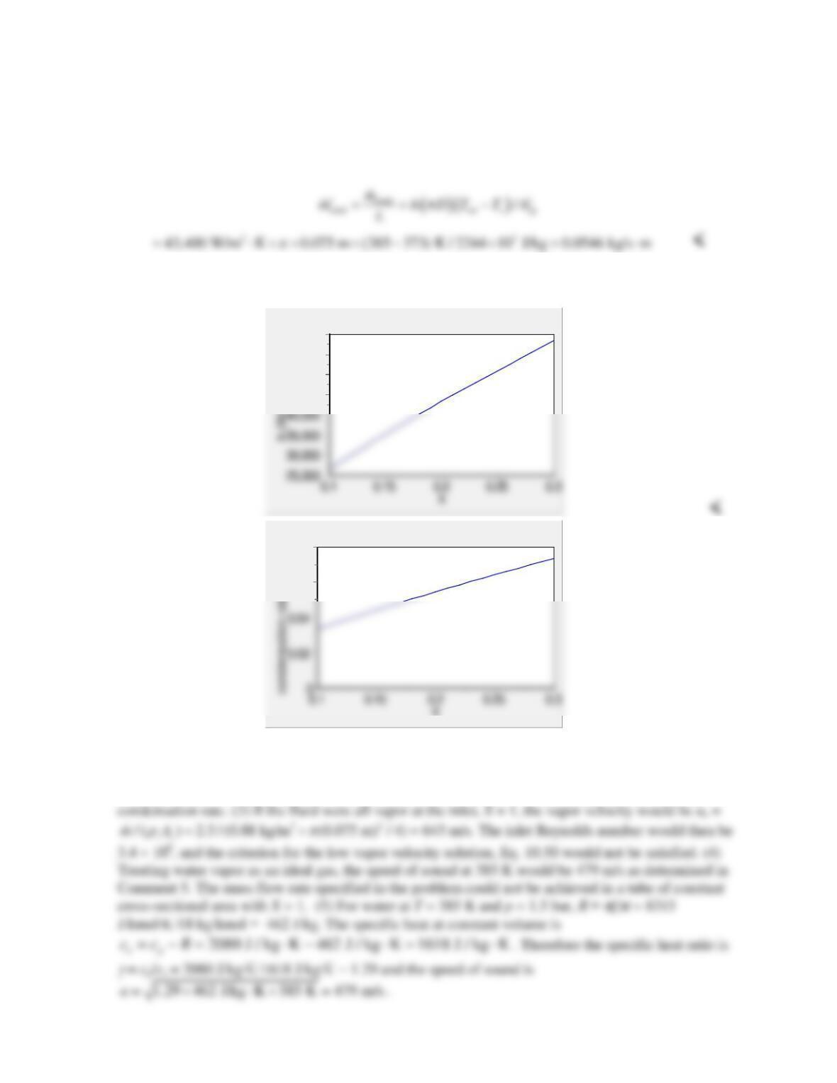
ANALYSIS: The mass flow rate per unit cross sectional tube area is
(0.075 m) / 4
c
A
π
Since this exceeds 500 kg/s ∙ m2, the Dobson and Chato correlation, Eq. 10.51a can be used. The
Reynolds number is
and the Martinelli parameter is
Then,
The heat transfer coefficient is
PROBLEM 10.50 (Cont.)
The condensation rate per unit length follows from Eq. 10.34 with A =
π
DL and
, sat
0.375 ( ) 2225 kJ/kg 0.375 4.232 kJ/kg K (385 373) K 2244 kJ/kg
fg fg p l s
h h cT T
′= + − = + × ⋅× − =
.
Thus,
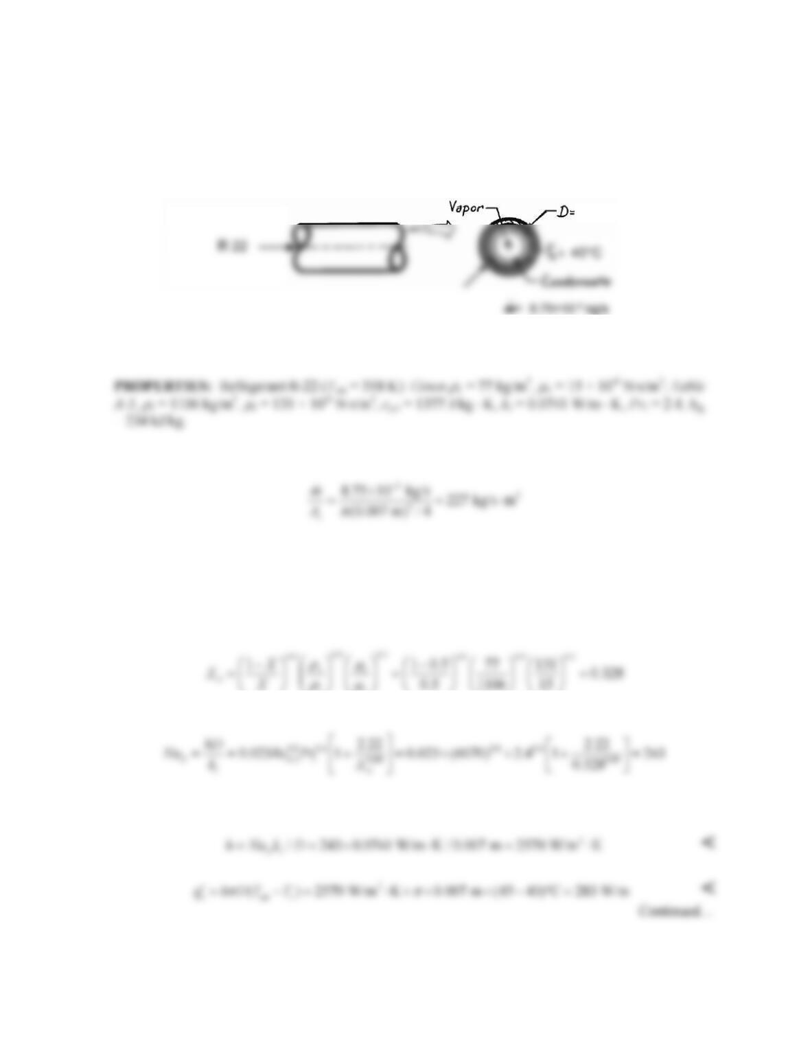
(b) Solving the same equations for 0.1 ≤ X ≤ 0.3 yields the plots below.
60,000
55,000
50,000
45,000
X
0.08
0.06
COMMENTS: (1) The value of X strongly impacts the heat transfer coefficient and condensation
rate. (2) The condensation rate corresponding to the low vapor velocity case of Problem 10.49 is 9.0 ×
10-3 kg/s ⋅ m. The higher vapor velocity yields a six-fold increase in heat transfer coefficient and
PROBLEM 10.51
KNOWN: Mass flow rate and quality of R-22 condensing in tube. Tube diameter. Wall and
saturation temperatures. Refrigerant properties.
FIND: Heat transfer coefficient, heat transfer rate, and condensation rate for (a) X = 0.5, (b) 0.2 < X <
0.8.
SCHEMATIC:
ASSUMPTIONS: (1) Film condensation with high vapor velocities, annular flow. (2) Heat of
vaporization not strong function of temperature.
ANALYSIS: The mass flow rate per unit cross sectional tube area is
Although this is below the recommended threshold of 500 kg/s ∙ m2, since annular flow was observed,
the Dobson and Chato correlation, Eq. 10.51a can be used. The Reynolds number is
3 62
,4 (1 ) / ( ) 4 8.75 10 kg/s (1 0.5) / ( 0.007 m 131 10 N s/m ) 6070
Dl l
Re m X D
πm π
−−
= − =× × ×− × × × ⋅ =
and the Martinelli parameter is
lv
Then,
The heat transfer coefficient and heat transfer rate per unit length are
7 mm
PROBLEM 10.51 (Cont.)
The condensation rate per unit length follows from Eq. 10.34 with A =
π
DL and
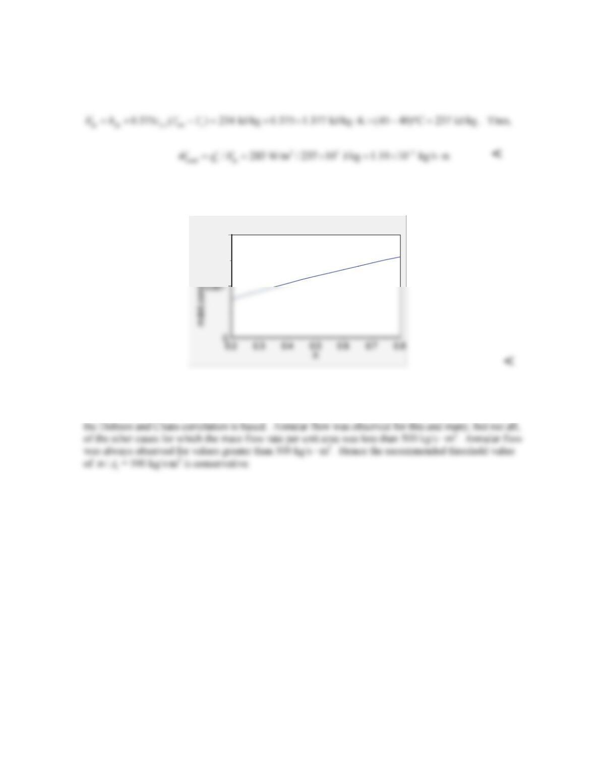
(b) Solving the same equations for 0.2 < X < 0.8 yields the condensation rate plot below.
0.002
COMMENTS: (1) The value of X strongly impacts the heat transfer coefficient, heat transfer rate,
and condensation rate. (2) This problem corresponds to one of the experimental conditions on which
PROBLEM 10.52
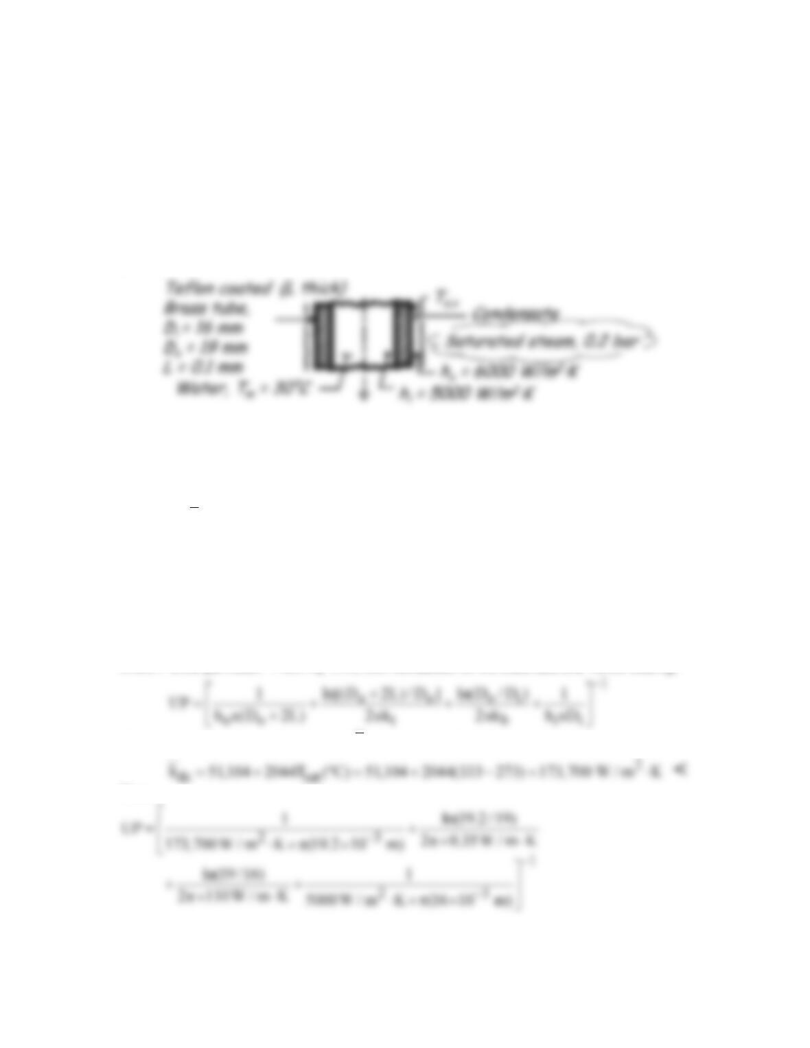
KNOWN: Inner and outer diameter of brass tube. Thickness of Teflon coating. Saturated
steam at 1 bar outside tube. Convection coefficient and mean temperature of water flowing inside
tube.
FIND: Condensation convection coefficient. Steam condensation rate per unit length.
Comparison with condensation rate for uncoated brass tube.
SCHEMATIC:
ASSUMPTIONS: (1) Dropwise condensation, (2) Correlations for a copper surface can be
applied to Teflon, and (3) Negligible effect of noncondensable vapors.
PROPERTIES: Table A.6, Water, vapor (0.2 bar): Tsat = 333 K, hfg = 2358 × 103 J/kg; Table
A.1, Brass
( )( )
m sat
T T T / 2 300K : k 110 W / m K
b
=+≈ = ⋅
; Table A.3, Teflon (T ≈ 300 K); kt =
0.35 W/m⋅K.
ANALYSIS: The condensation rate per unit length follows from Eq. 10.34 written as
fg
m q /h
′ ′′
=
(1)
where the heat rate per unit length follows from Eq. 10.33 using an overall heat transfer
coefficient
( )
sat m
q UP T T
′= −
(2)
where P is the perimeter. From Eq. 3.36, with resistances for the brass tube and Teflon coating,
The outer heat transfer coefficient, ho =
dc
h
, can be calculated from Eq. 10.52,
Thus
Continued…
PROBLEM 10.52 (Cont.)
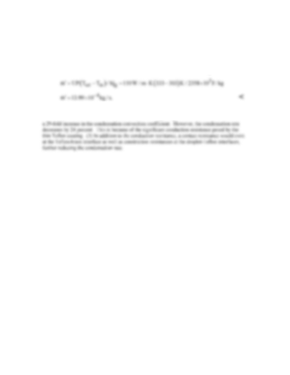
1
4343
UP 0.95 10 4.76 10 2.49 10 3.98 10 W / m K 110 W / m K.
−
−−−−
= × +× +× +× ⋅= ⋅
Combining Eqs. (1) and (2) and substituting numerical values (see below for
fg
h′
), find
COMMENTS: (1) Since the outer convection resistance is small relative to the sum of the
remaining resistances, Ts,o ≈ Tsat and from Eq. 10.27,
fg fg
hh
′≈
. (2) The Teflon coating induces
PROBLEM 10.53
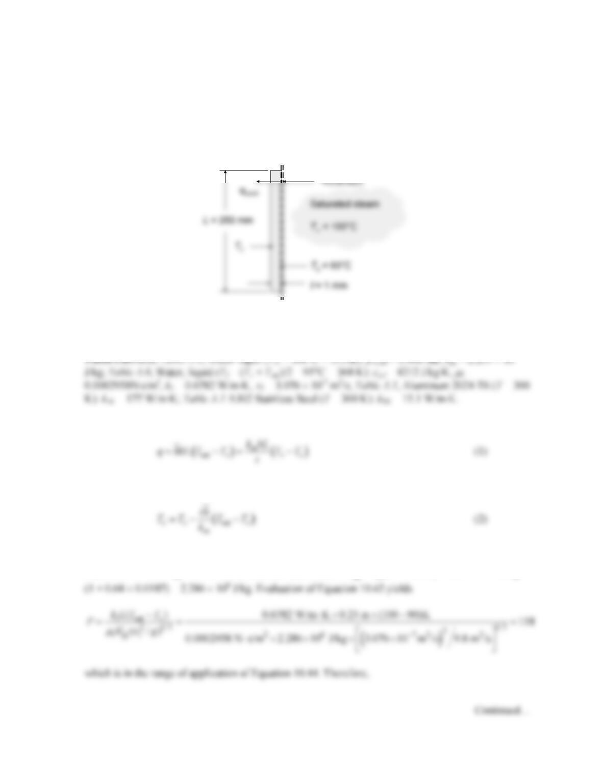
KNOWN: Conditions of saturated steam. Surface temperature of aluminum and stainless steel plates
of known dimension.
FIND: (a) Temperature of the cold surface of the aluminum plate, (b) Temperature of the cold
surface of the stainless steel plate.
SCHEMATIC:
ASSUMPTIONS: (1) Dropwise condensation on stainless steel described by Equation 10.52, (2)
Filmwise condensation on aluminum, (3) Constant properties, (4) Steady state.
ANALYSIS: An energy balance for the control surface at Ts yields
where km is the thermal conductivity of the metal plate. Equation (1) may be rearranged to yield
(a) For filmwise condensation on the aluminum plate, Ja = cp,l(Tsat – Ts)/hfg = 4212 J/kg⋅K(100 –
90)K/2.257 × 106 J/kg = 0.0187. The modified latent heat is
fg
h′
= hfg(1 + 0.68Ja) = 2.257 × 10⁶ J/kg ×
b= 100 mm
q
PROBLEM 10.53 (Cont.)
0.82
2 1/3
1(0.68 0.89)
( /)
l
L
l
k
hP
P
g
ν
= +
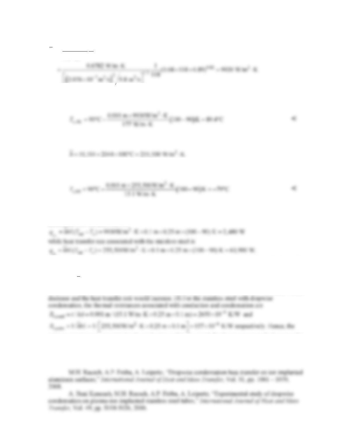
From Equation (2), the cold surface temperature is
(b) For dropwise condensation on the stainless steel plate, Equation 10.52 yields
From Equation (2), the cold surface temperature is
COMMENTS: (1) The required cold surface temperature associated with the stainless steel is very
low, compared to the corresponding value associated with the aluminum. (2) The heat transfer rate
associated with the aluminum is
(3) For the aluminum with film condensation, the thermal resistances associated with conduction and
condensation are
6
,cond / 0.001 m / (177 W/m K 0.25 m 0.1 m) 225 10 K/W
t
R t kA −
= = ⋅× × = ×
and
26
,conv 1/ 1/ 9930 W/m K 0.25 m 0.1 m 4030 10 K/W
t
R hbL −
= = ⋅× × = ×
respectively. Hence, if
dropwise condensation could be promoted on the aluminum plate, the overall thermal resistance would
primary resistance is associated with conduction within the metal. Further increases in the heat transfer
coefficient associated with the condensation would not significantly increase the heat transfer rate. (5)
Further information on the ion implantation effect on condensation is available in the following two
references.