
1. The pressure drop for a 100 ft run of pipe (∆p= 227 psf ≈1.6psi )could be
61
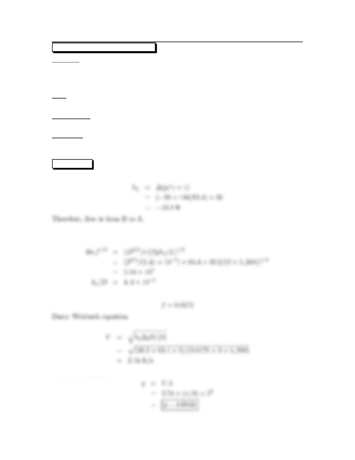
10.44: PROBLEM DEFINITION
Situation:
Water flows with a through a horizontal run of PVC pipe
V=2m/s,L=50m.
Nominal diameter 2.5″ Schedule 40. D=2.45 in.=0.0622 m.
Find:
(a) Pressure drop in kPa.
(b) Head loss in meters.
(c) Power in watts needed to overcome the head loss.
Assumptions:
1.) Assume ks=0.
2.) Assume α1=α2, where subscripts 1 and 2 denote the inlet and exit of the pipe.
Properties:
Water (10 ◦C),TableA.5:
ρ=1000kg/m3,γ=9810N/m3,ν=1.31 ×10−6m2/s.
PLAN
To establish laminar or turbulent flow, calculate the Reynolds number. Then find
the appropriate friction factor (f)and apply the Darcy-Weisbach equation to find
the head loss. Next, find the pressure drop using the energy equation. Lastly, find
power using P=˙mghf.
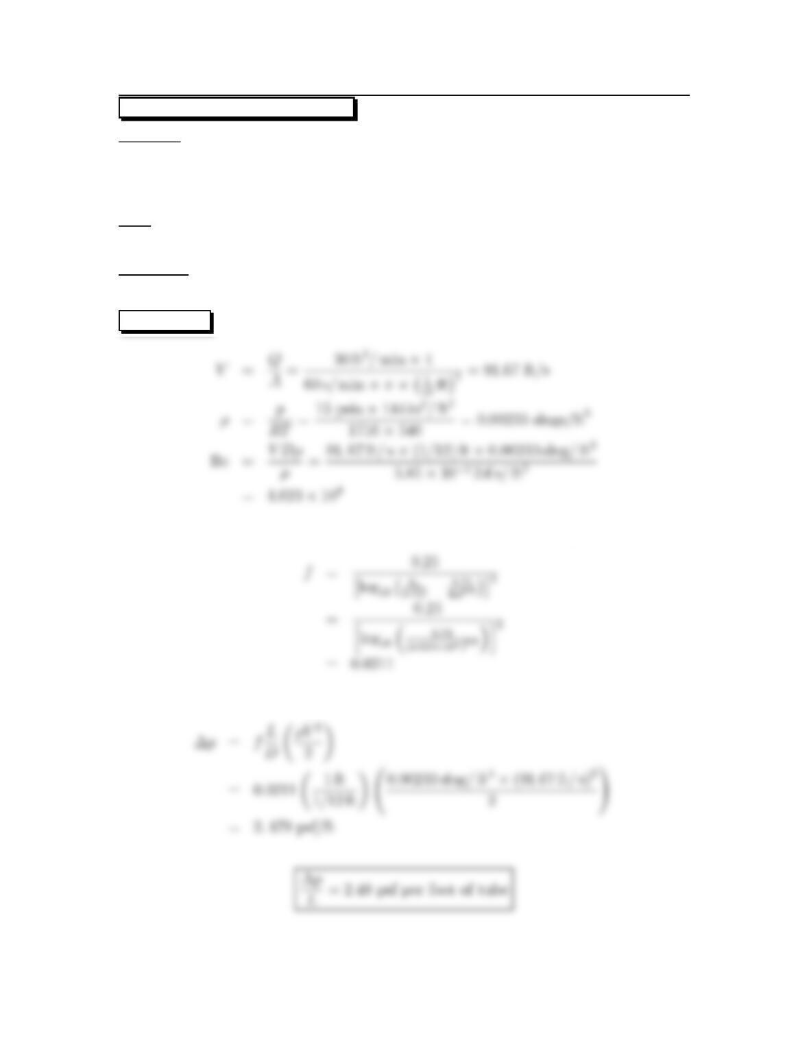
SOLUTION
Reynolds number
Friction factor (f)(Swamee-Jain equation)
62
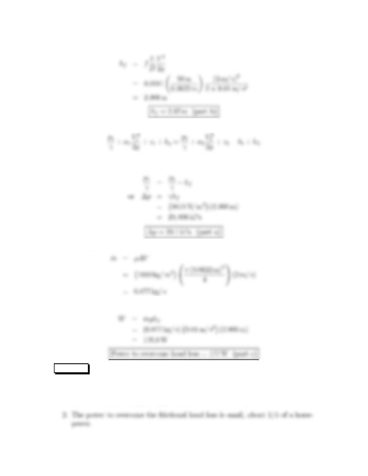
Darcy-Weisbach equation
Energy equation
Select a control volume surrounding the pipe. After analysis of each term, the energy
equation simplifies to
Flow rate equation
Power equation
REVIEW
1. The pressure drop (29 kPa) is about 1/3 of an atmosphere This value could be
decreased by increasing the pipe diameter to lower the speed of the water.
63
10.45: PROBLEM DEFINITION
Situation:
Air flows through a smooth tube.
Q=0.015 m3/s,D=3cm.
p=110kPa-absolute.
Find:
Pressure drop per meter of tube length.
Properties:
Air (20 ◦C)TableA.3:μ=1.81 ×10⁻⁵N·s/m2,ρ=1.2kg/m3.
Assumptions:
1. Pipe is horizontal.
2. Fully developed flow so Vand αare constant.
PLAN Solve the problem by applying the energy equation. The steps are:
1. Develop an equation for ∆pby applying the energy equation.
3. Calculate ρusing the ideal gas law
5. Look up fon the Moody diagram using the Re from step 4.
7. Combine results.
SOLUTION
1. Energy equation (cv surrounding a 1-m length of pipe)
2. Flow rate equation
64
3. Ideal gas law
4. Reynolds number
6. Darcy Weisbach equation
7. Combine results
65
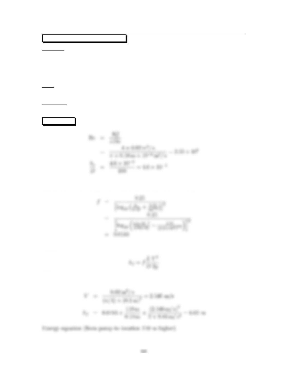
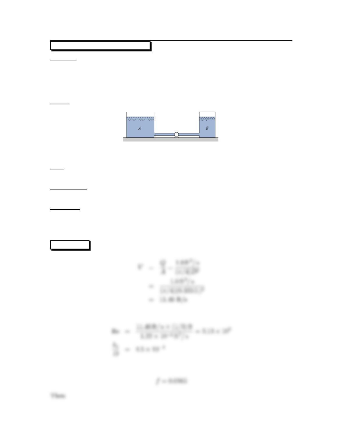
10.46: PROBLEM DEFINITION
Situation:
Water flowsfrompointAtoBinacastironpipe.
L=3mi,D=24in.
∆pB−A=20psi, ∆hA−B=30ft.
Find:
Direction and rate of flow ¡ft3/s¢.
Assumptions:
Flow is from A to B.
Properties:
Water (50 ◦F),TableA.5:ν=1.41 ×10⁻⁵ft2/s.
Pipe Roughness, Table 10.4 (EFM10e), ks=0.01 in = 0.000833 ft.
SOLUTION
Parameters for the Moody diagram, Fig. 10.14 in 10e
Resistance coefficient (from the Moody diagram, Fig. 10.14 in 10e)
Flow rate equation
66
10.47: PROBLEM DEFINITION
Situation:
Air flows through a smooth tube.
D=1in,Q=30ft
3/min.
p=15psia.
Find:
Pressure drop per foot of tube.
Properties:
Air (80oF) Table A.3: μ=3.85 ×10⁻⁷lbf-s/ft2.
SOLUTION
Resistance coefficient (f)(Swamee-Jain correlation; turbulent flow)
Pressure drop
67
10.48: PROBLEM DEFINITION
Situation:
Water is pumped through a vertical steel pipe to an elevated tank.
D=10cm,p1=1.6MPa.
L=110m,Q=0.02 m3/s.
∆z=110m
Find:
Pressure at point 110 m above pump.
Properties:
Water (20 ◦C),TableA.5: γ=9790N/m3.
SOLUTION
Resistance coefficient (Swamee-Jain correlation; turbulent flow)
Then
where
69
10.49: PROBLEM DEFINITION
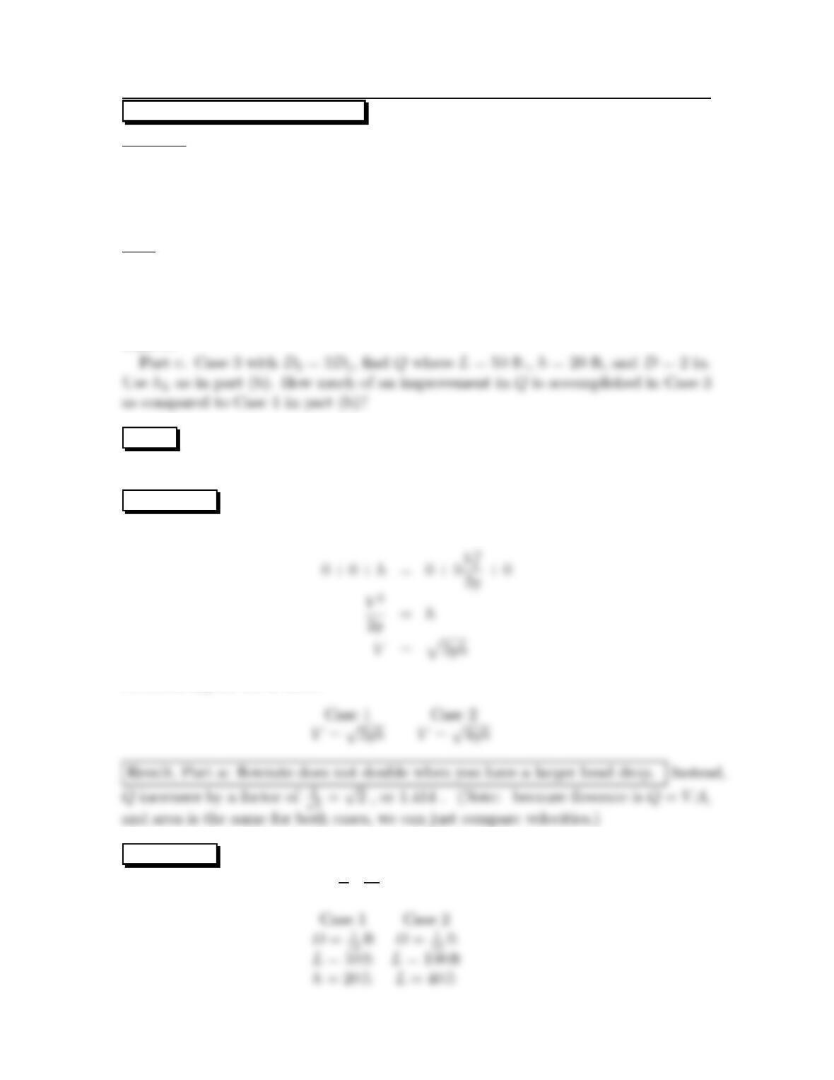
Situation:
Basement siphoning situation.
Case 1: length Land height h
Case 2: length 2Land height 2h
Case 3: length L,heighth, and D3=2D1
Find:
Part a. Assume hL=0,find whether Qdoubles when the Lis doubled from Case
1toCase2.
Part b. Assume hL=0.025(L/D)(V2/2g),find Qfor Cases 1 and 2 , where D=1
in., L=50ft., and h=20ft. How much does Qincrease for Case 2 as compared to
Case 1?
PLAN
Employ energy equation
SOLUTION
Part a. Assume hL=0.The following is true for each case:
Now, solving for the 2 cases:
SOLUTION
Part b. Assume hL=0.025( L
D)(V2
2g)
70
The following is true for each case:
Solve for velocity for each of the two cases:
Result, Part b: there is only a small ↑V(and therefore Q) by lengthening the ∆h;
this is because by increasing the L, one increases the head loss. With these data, Q
SOLUTION
Part c. Increase hose diameter (Case 3).
Compare Case 1 to Case 3; Use the same form of hLas in Part b.
Result, Part c: With a larger diameter, we have less head loss (than by lengthening the hose)
so more of the head difference provided by the siphon can result in velocity. Also, area
doubles. With these data, Qwould increase by a factor of Q3
Q1=V3A3
V1A1=12.3(2A1)
8.97(A1)=
factor of 2.74. This is the best improvement of all.
REVIEW Ifyouneedtoincreasetheflow from a siphon, get a bigger hose, or get
more hoses. Don’t lengthen the hose.
71
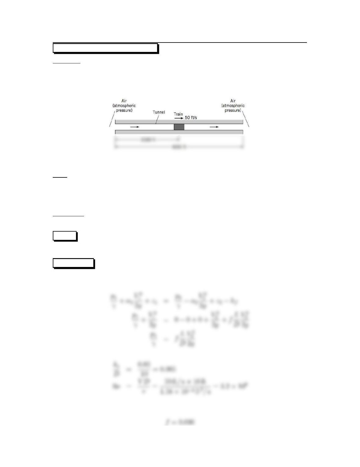
10.50: PROBLEM DEFINITION
Situation:
A train travels through a tunnel.
D=10ft,ks=0.05 ft.
V=50ft/s,L=2500ft
Find:
(a) Change in pressure between the front and rear of the train.
(b) Power required to produce the air flow in the tunnel.
(c)SketchanEGLandaHGL.
Properties:
Air (60 ◦F)TableA.3:γ=0.0764 lbf/ft3,ν=1.58 ×10−4ft2/s.
PLAN
Apply the energy equation from front of train to outlet of tunnel.
SOLUTION
Energy equation
Resistance coefficient (from Moody diagram)
72
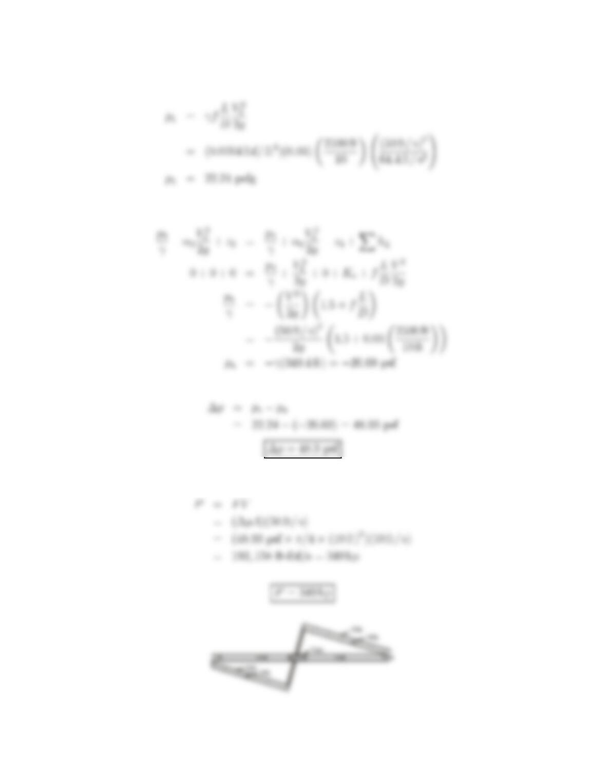
Darcy Weisbach equation
Energy equation (from outside entrance to rear of train)
Power equation
73
10.51: PROBLEM DEFINITION
Situation:
Water is pumped from a reservoir to a tank.
D=4in,L=300ft.
Q=1ft
3/s,η=0.9.
pB=10psig, pA=0psig.
Sketch:
Find:
Power to operate the pump.
Assumptions:
Assumetheentranceissmooth.
Properties:
Water (60 ◦F) Table A.5: ν=1.22 ×10⁻⁵ft2/s.
Pipe roughness, Table 10.4 (EFM10e), ks=0.002 in = 1.67 ×10⁻⁵ft.
Loss Coefficients, Table 10.5 (EFM10e), Ke=0.03,KE=1.
SOLUTION Flow rate equation
Then
Resistance coefficient (from Moody diagram)
74
Energy equation (from water surface Ato water surface B)
Thus
Power equation
75
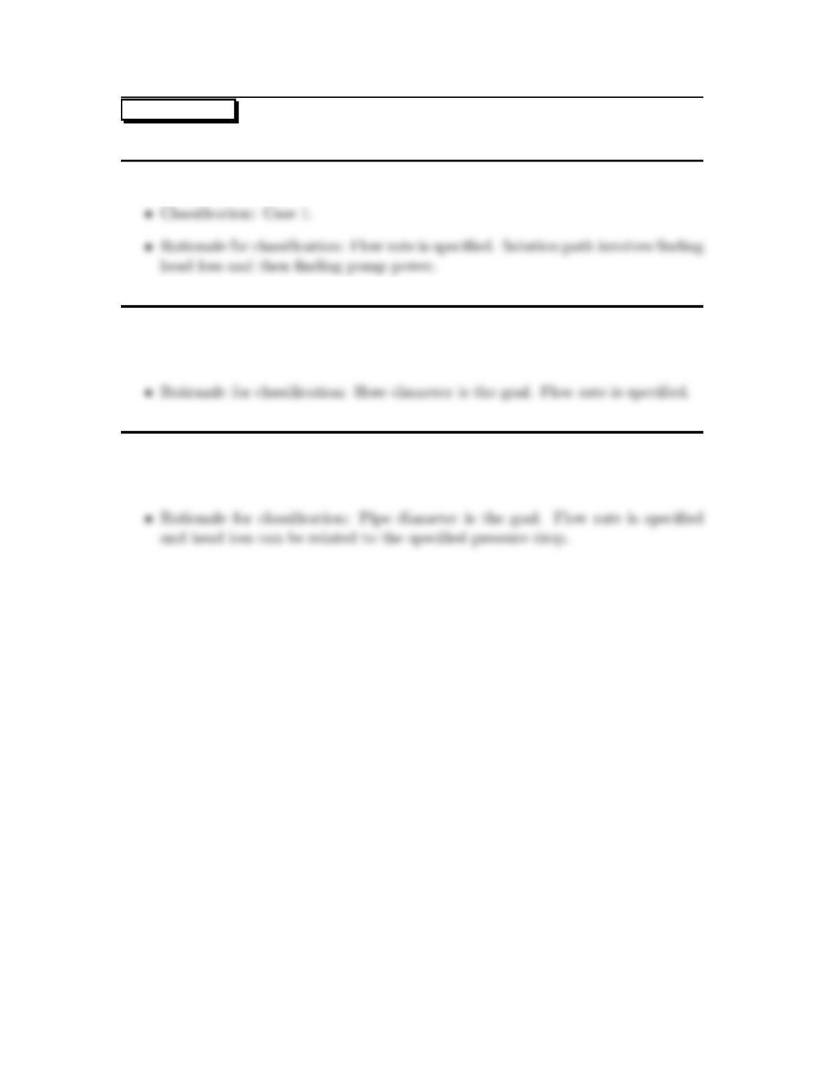
Problem 10.52
Classify problems as case 1, 2, or 3.
a. Problem 10.51 (EFM 10e)
b. Problem 10.54 (EFM 10e)
•Classification: Case 3.
c. Problem 10.57 (EFM 10e)
•Classification: Case 3.
76
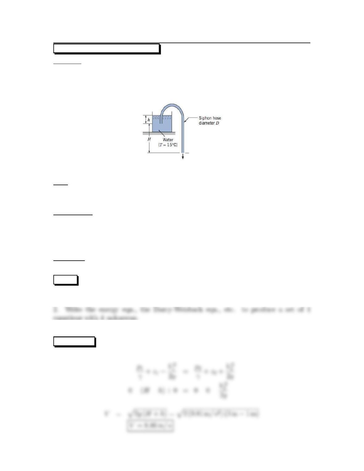
10.53: PROBLEM DEFINITION
Situation:
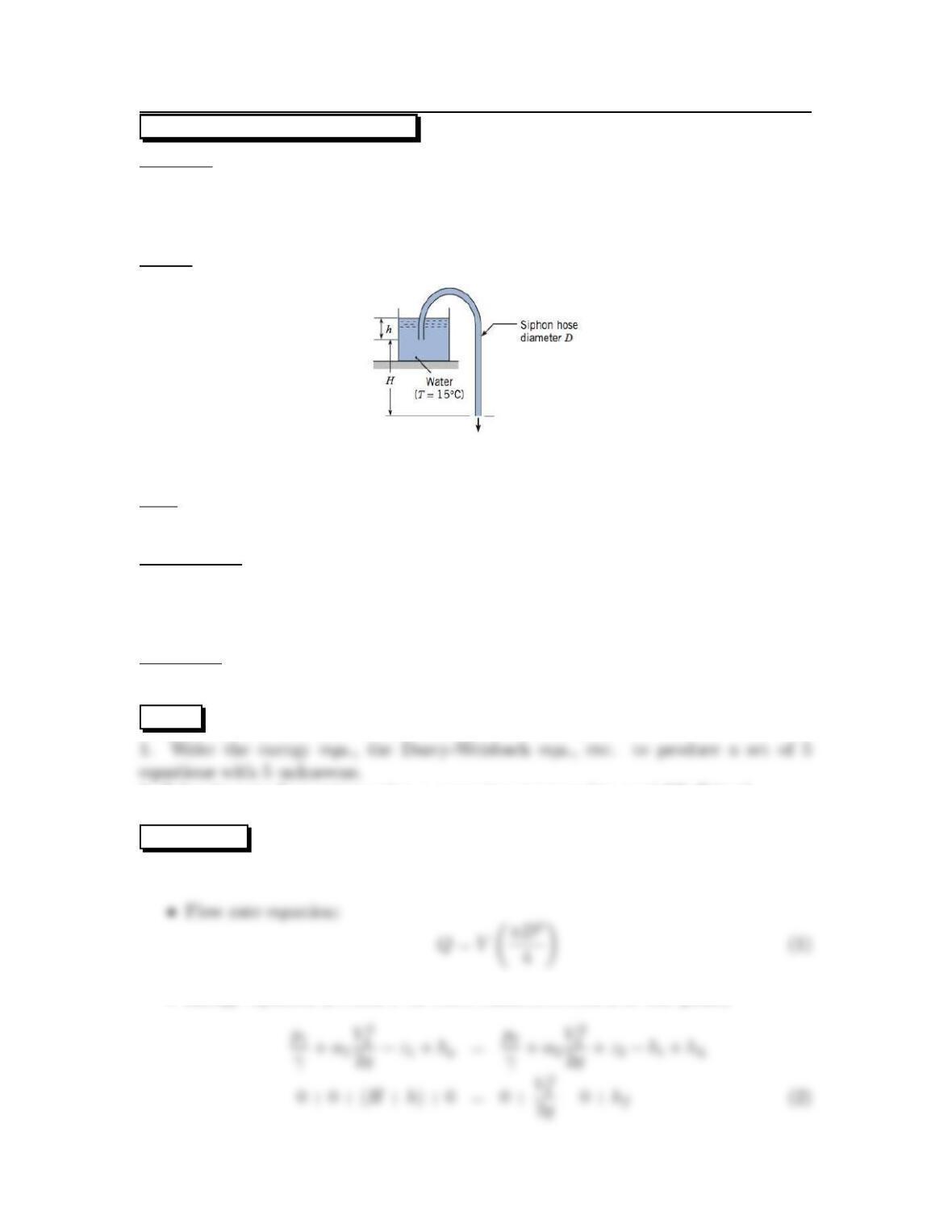
Water is flowing out a plastic siphon hose.
D=0.012 m,H=3m.
h=1.0m,L=5.5m.
ks=0.
Find:
Velocity (assume the Bernoulli equation applies).
Velocity (include the head loss in the hose).
Assumptions:
Steady flow.
Neglect all head loss (part 1 of problem).
Neglect component head loss (part 2 of problem).
Turbulent flow. Also, α2=1.0.
Properties:
Water (15 ◦C), Table A.5: ν=1.14 ×10⁻⁶m2/s.
PLAN
1. Use the Bernoulli equation to find velocity
Classify this problem as case 2 (Vis unknown), then
3. Solve the set of equations using a computer program (we used TK Solver).
SOLUTION
1. Bernoulli equation (point 1 on tank surface; point 2 on exit plane of hose):
77
2. Equations for finding velocity:
•Energy equation:
3. Solution of Eqs. (1) to (4):
REVIEW
1. Notice that the turbulent flow assumption is valid because Re >2300.
78
10.54: PROBLEM DEFINITION
Situation:
Water is flowing out a plastic siphon hose.
Q=0.0015 m3/s,H=5m.
h=0.5m,L=7m,k
s=0.
Sketch:
Find:
Diameter of hose (meters).
Assumptions:
Steady flow.
Component head loss is zero.
Turbulent flow. Also, α2=1.0.
Properties:
Water (15 ◦C), Table A.5, ν=1.14 ×10⁻⁶m2/s.
PLAN Classify this problem as case 3 (Dis unknown), then
2. Solve the set of equations using a computer program (we used TK Solver).
SOLUTION
1. Governing equations:
•Energy equation (section 1 on water surface, section 2 at exit plane)
79
•Darcy-Weisbach:
3. Solution of Eqs. (1) to (5):
REVIEW
•Notice that the turbulent flow assumption is valid because Re >2300.
•Notice that most of the elevation head (5.5m)is converted to head loss (4.72 m) .
80