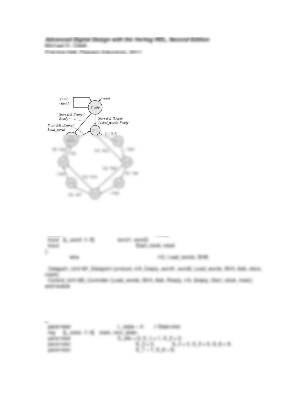
Problem 10-2
The STG of Figure 10-19(b) has been modified to handle an empty multiplier or
multiplicand.
Note that Ready is effectively a Moore signal.
module Prob_10_2_Multiplier_STG_0 #(parameter L_word = 4)(
output [2*L_word -1: 0] product,
output Ready,
module Control_Unit #(parameter L_word = 4)(
output reg Load_words, Shift, Add,
output Ready,
input m0, Empty, Start, clock, reset
assign Ready = ((state == S_idle) && !reset) || (state == S_8);
always @ (state, Start, m0) begin // Next state and control logic
Ready = 0; Load_words = 0; Shift = 0; Add = 0;
case (state)
S_idle: if (Start) begin
if(!Empty) begin Load_words = 1; next_state = S_1; end
else next_state = S_8;
else next_state = S_idle;
S_1: if (m0) begin Add = 1; next_state = S_2; end
module Datapath_Unit #(parameter L_word = 4)(
output reg [2*L_word -1: 0] product,
output m0, Empty,
input [L_word -1: 0] word1, word2,
input Load_words, Shift, Add, clock, reset
);
reg [2*L_word -1: 0] multiplicand;
reg [L_word -1: 0] multiplier;
///*
module test_Multiplier_STG_0 ();
parameter L_word = 4;
wire [2*L_word -1: 0] product;
wire Ready;
integer word1, word2; // multiplicand, multiplier
reg Start, clock, reset;
always @ (posedge clock) // Compare product with expected value
if (Start) begin
#5 expected_value = 0;
expected_value = word2 * word1;
// expected_value = word2 * word1 + 1; // Use to check error detection
code_error = 0;
end
else begin
code_error = (M1.M2.state == M1.M2.S_8) ? |(expected_value ^ product) : 0;
end
initial begin clock = 0; forever #10 clock = ~clock; end
initial begin
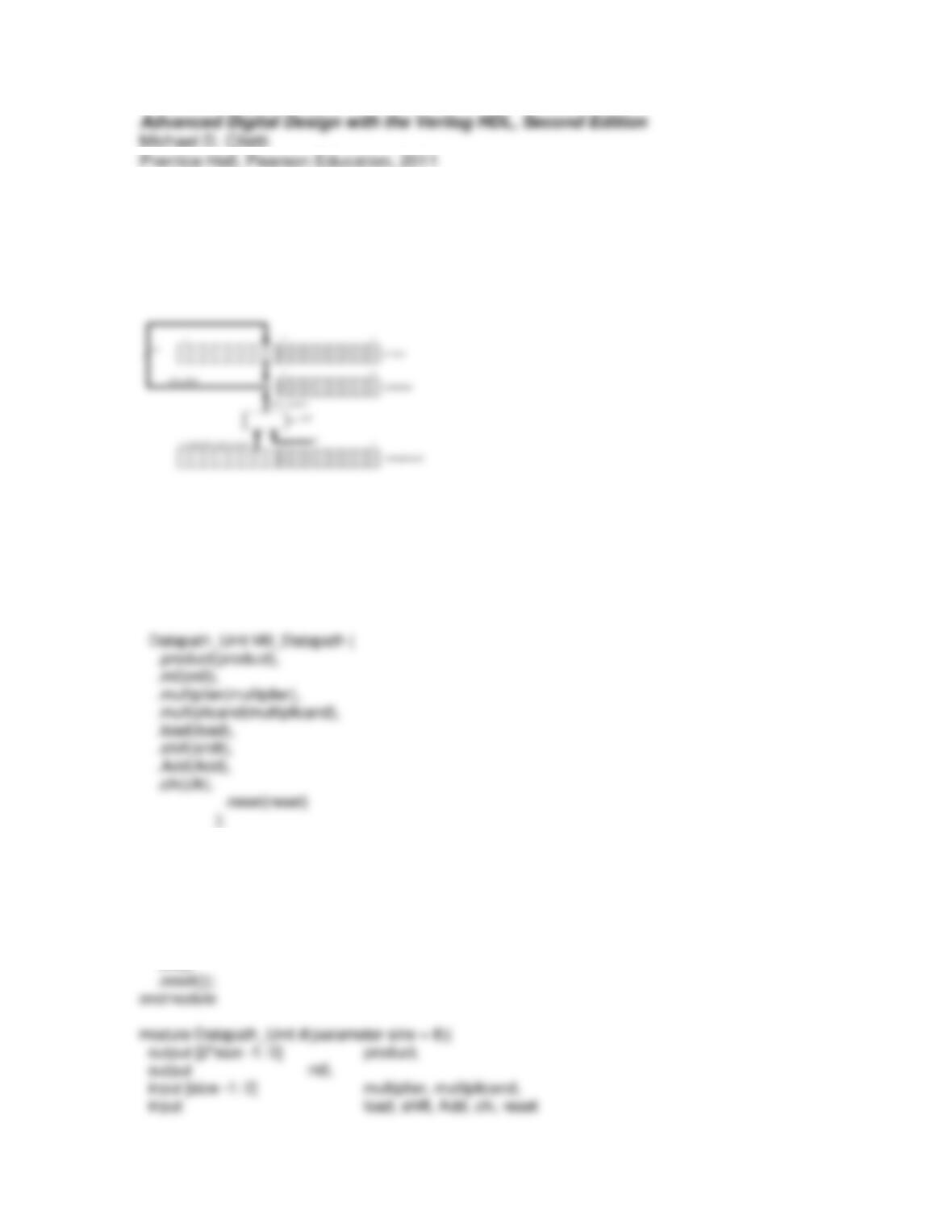
Problem 10-3
The structural model has the architecture shown below. It includes a mux to control the
datapath to the adder. This allows a shifted copy of the multiplicand to be added to the
product register only when the LSB of the multipler is 1. The control unit is taken from
Example 10.1.
module Multiplier_Structural_Model #(parameter size = 8)(
output [2*size -1: 0] product,
output Ready,
input [size -1: 0] multiplier, multiplicand,
input Start, clk, reset
);
wire m0, Add, load, shift;
Control_Unit M1_Controller (
.Start(Start),
.Load_words(load),
.Shift(shift),
.Add(Add),
.m0(m0),
.clk(),
);
wire [2*size -1: 0] multiplicand_register, Mux_data, sum_data;
Par_Load_16bit_Shift_Register M1_Multiplicand_Reg (
.word_out(multiplicand_register),
.word_in(multiplicand),
.load(load),
.shift(shift),
.clk(clk),
.reset(reset)
);
);
Data_mux M4_Mux (
.data_out(Mux_data),
.data_in(Multiplicand_Register)
.Add (Add)
);
endmodule
module Par_Load_16bit_Shift_Register #(parameter size = 8) (
output reg [2*size -1: 0] word_out,
input [size -1: 0] word_in,
input load, shift, clk, reset
);
always @ (posedge clk, negedge reset)
if (!reset) word_out <= 0;
else if (load) word_out <= {size{1’b0}, word_in};
input load, clk, reset
);
always @ (posedge clk, negedge reset)
if (!reset) word_out <= 0;
else if (load) word_out <= word_in;
endmodule
endmodule
module Add_16 #(parameter size = 16)(
output [size-1: 0] sum,
input [size -1: 0] word1, word2;
);
assign sum = word1 + word2;
endmodule
input m0, Start, clock, reset
);
parameter L_state = 4; // State size
reg [L_state -1: 0] state, next_state;
parameter S_idle = 0, S_1 = 1, S_2 = 2;
parameter S_3 = 3, S_4 = 4, S_5 = 5, S_6 = 6;
parameter S_7 = 7, S_8 = 8;
assign Ready = ((state == S_idle) && !reset) || (state == S_8);
else begin Shift = 1; next_state = S_3; end
S_2: begin Shift = 1; next_state = S_3; end
S_3: if (m0) begin Add = 1; next_state = S_4; end
else begin Shift = 1; next_state = S_5; end
S_4: begin Shift = 1; next_state = S_5; end
module test_Multiplier_Structural_Model #(parameter L_word = 8) ();
wire [2*L_word -1: 0] product;
wire Ready;
integer word1, word2; // multiplicand, multiplier
reg Start, clock, reset;
Multiplier_Structural_Model M0_Multiplier (
);
// Exhaustive Testbench
reg [2*L_word -1: 0] expected_value;
reg code_error;
initial #80000 finish; // Timeout
always @ (posedge clock) // Compare product with expected value
if (Start) begin
#5 expected_value = 0;

Start = 0; #40 Start = 1;
#20 Start = 0;
#200;
Problem 10-4
(a) Consider Fig. 10-19 (b), and observe that the determination of whether multiplier is
empty should be made after the shift operation, i.e., in states S_1, S_3, S_4, S_5, and
S_7. The datapath unit has a new status signal, empty_multiplier, which signals to the
control unit that multiplier is empy of 1s. The new STG is shown below.
S_idle
reset
!reset
/ Ready
The model for Multiplier_STG_0 becomes:
module Prob_10_4_Multiplier_STG_0 #(parameter L_word = 4)(
output [2*L_word -1: 0] product,
output Ready,
);
parameter L_state = 4; // State size
reg [L_state -1: 0] state, next_state;
parameter S_idle = 0, S_1 = 1, S_2 = 2;
S_idle: if (Start) begin Load_words = 1; next_state = S_1; end
else next_state = S_idle;
S_1: if (m0) begin Add = 1; next_state = S_2; end
else begin Shift = 1; next_state = S_3; end
S_5: if(empty_multiplier) next_state = S_8;
else if (m0) begin Add = 1; next_state = S_6; end
else begin Shift = 1; next_state = S_7; end
S_6: begin Shift = 1; next_state = S_7; end
S_7: if (m0) begin Add = 1; next_state = S_8; end
else begin next_state = S_8; end // remove Shift =1 5-10-04
input [L_word -1: 0] word1, word2,
input Load_words, Shift, Add,
input clock, reset
endmodule
///*
module test_Multiplier_STG_0 ();
parameter L_word = 4;
wire [2*L_word -1: 0] product;
wire Ready;
integer word1, word2; // multiplicand, multiplier
reg Start, clock, reset;
Multiplier_STG_0 M1 (product, Ready, word1, word2, Start, clock, reset);
// Exhaustive Testbench
reg [2*L_word -1: 0] expected_value;
reg code_error;
initial #80000 $finish; // Timeout
Start = 0; #40 Start = 1;
(b) Consider Fig. 10-19 (b), and observe that the determination of whether multiplier is
empty should be made after the shift operation, i.e., in states S_1, S_3, S_4, S_5, and
S_7. The datapath unit has a new status signal, empty_multiplier, which signals to the
control unit that multiplier is empy of 1s. The modified STG is given below.
The model for Multiplier_STG_0 becomes:
module Prob_10_4_Multiplier_STG_1 #(parameter L_word = 4)(
output [2*L_word -1: 0] product,
endmodule
module Control_Unit #(parameter L_word = 4)(
output reg Load_words, Shift, Add_shift,
output Ready,
input m0, empty_multiplier, Empty, Start, clock, reset
);
always @ (state, Start, m0, Empty) begin // Next state and control logic
Load_words = 0; Shift = 0; Add_shift = 0;
case (state)
S_idle: if (Start && Empty) next_state = S_5;
else if (Start) begin Load_words = 1; next_state = S_1; end
else next_state = S_idle;
S_1: begin if (m0) Add_shift = 1; else Shift = 1; next_state = S_2; end
module Datapath_Unit #(parameter L_word = 4)(
output reg [2*L_word -1: 0] product,
output m0, empty_multiplier, Empty,
input [L_word -1: 0] word1, word2,
input Ready, Start, Load_words, Shift,
input Add_shift, clock, reset
);
multiplier <= word2;
product <= 0;
end
else if (Shift) begin
multiplier <= multiplier >> 1;
module test_Multiplier_STG_1 ();
parameter L_word = 4;
wire [2*L_word -1: 0] product;
wire Ready;
integer word1, word2; // multiplicand, multiplier
reg Start, clock, reset;
Multiplier_STG_1 M1 (product, Ready, word1, word2, Start, clock, reset);
// Exhaustive Testbench
reg [2*L_word -1: 0] expected_value;
reg code_error;
end
initial begin clock = 0; forever #10 clock = ~clock; end
initial begin
#0 reset = 1;
#815 reset = 0;
end

Problem 10-5
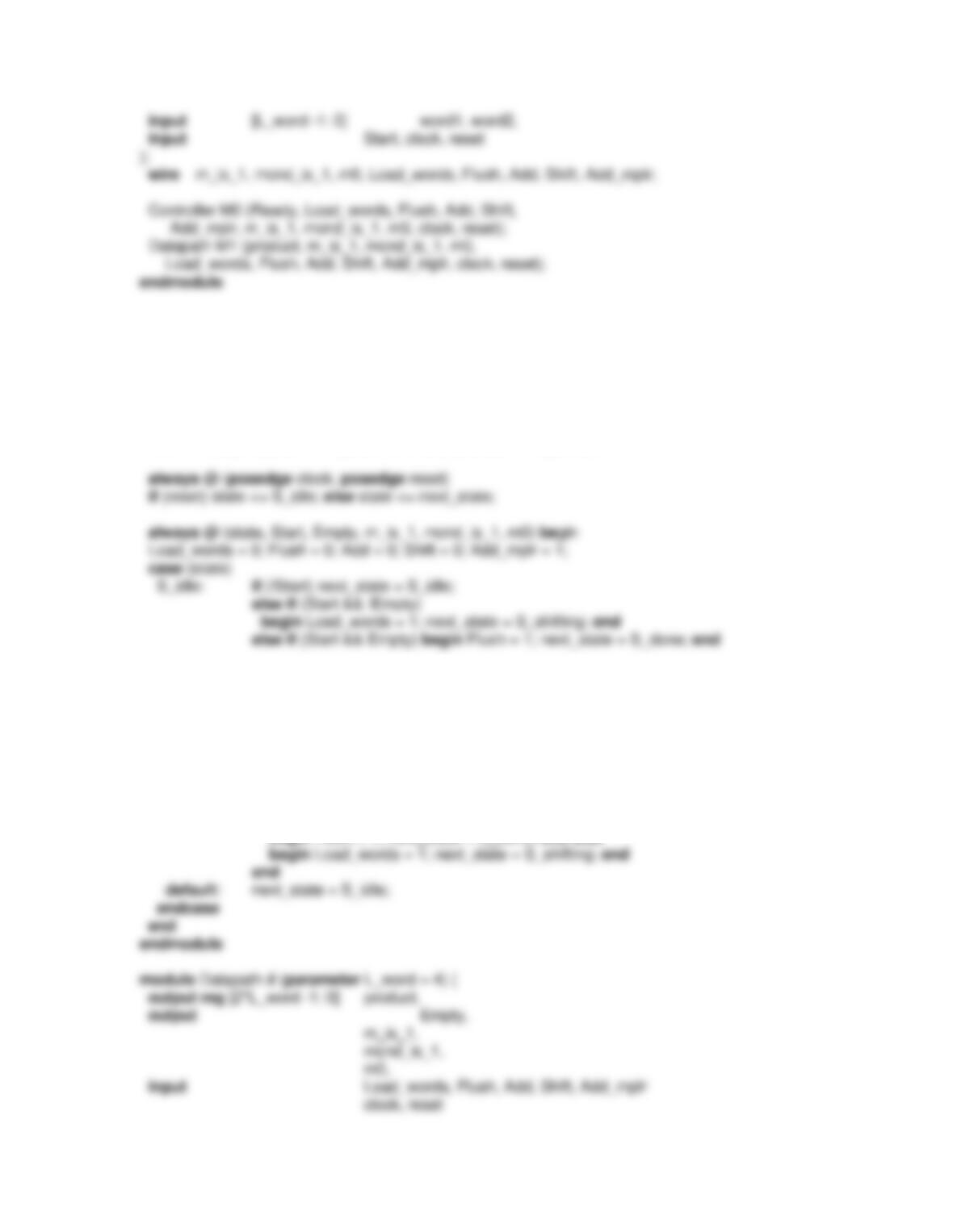
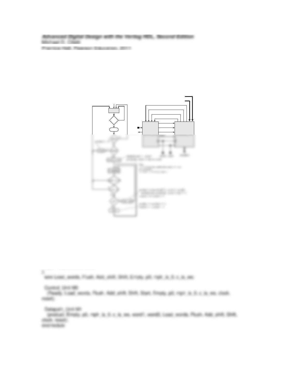
If multiplicand is 1 the result of multiplication will be the value of the multiplier. The
ASMD chart ismodified to detect this case and then set product to the value of multiplier.
The revised model is given below:
module Prob_10_5_Multiplier_ASM_0 # (parameter L_word = 4) (
output reg [2*L_word -1: 0] product,
output Ready,
module Controller # (parameter L_word = 4) (
output Ready,
output reg Load_words, Flush, Add, Shift, Add_mplr,
input m_is_1, mcnd_is_1, m0, clock, reset
);
reg [1: 0] state, next_state;
parameter S_idle = 0, S_shifting = 1, S_adding = 2, S_done = 3;
wire Ready = ((state == S_idle) && !reset) || (state == S_done);
S_shifting: if (mcnd_is_1) begin next_state = S_done; Add_mplr = 1; end
else if (m_is_1) begin Add = 1; next_state = S_done; end
else if (m0) begin Add = 1; next_state = S_adding; end
else begin Shift = 1; next_state = S_shifting; end
S_adding: begin Shift = 1; next_state = S_shifting; end
S_done: begin if (Start == 0) next_state = S_done;
else if (Empty)
begin Flush = 1; next_state = S_done; end else
);
reg [2*L_word -1: 0] multiplicand;
reg [L_word -1: 0] multiplier;
else begin
if (Flush) product <= 0;
if (Load_words == 1) begin
multiplicand <= word1;
multiplier <= word2;
product <= 0;
end
Problem 10-6
The modified ASMD chart is shown below. The status signal mplr_is_0 indicates the
condition that the multiplier is empty of 1s.
S_idle
reset
Ready
reset 1
0
Load_words
Start
Empty
Add_shift
Flush
Ready
p0
c_is_ws
word2
word1
mplr_is_0
The modified machine has the model:
module Prob_10_6_Multiplier_RR_ASM #(parameter L_word = 4)(
output [2*L_word: 0] product,
output Ready,
input [L_word -1: 0] word1, word2,
input Start, clock, reset
module Control_Unit (
output Ready, output reg Load_words, Flush, Add_shift, Shift,
input Start, Empty, p0, c_is_ws, clock, reset
);
reg state, next_state;
parameter S_idle = 0, S_running = 1;
assign Ready = (state == S_idle) && (!reset );
S_running: if (mplr_is_0) next_state = S_idlel
else if (c_is_ws) next_state = S_idle;
else begin
if (p0) begin Add_shift = 1; next_state = S_running; end
else begin Shift = 1; next_state = S_running; end
end
);
reg [L_word -1: 0] multiplicand;
reg [L_count -1 : 0] counter;
assign Empty = (word1 == 0) || (word2 == 0);
assign p0 = product[0];
assign mplr_is_0 = (multiplier == 0);
assign c_is_ws = (counter == L_word);