10.95: PROBLEM DEFINITION
Situation:
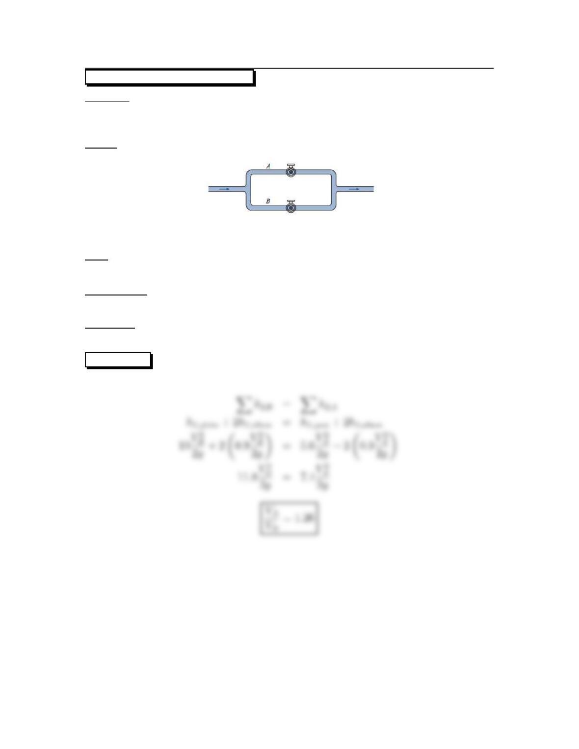
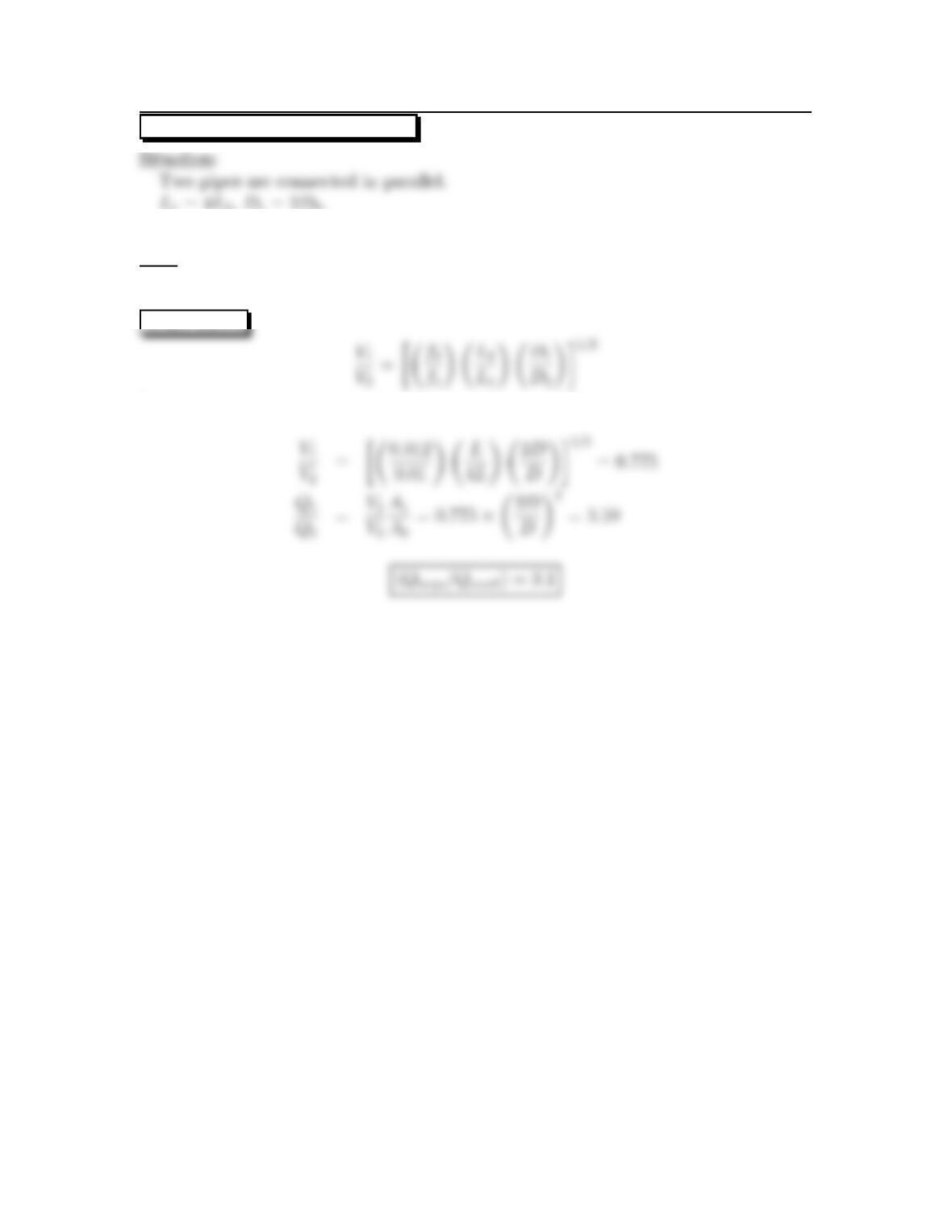
Two pipes are connected in parallel.
Line A has a half open gate valve, line B a fully open globe valve.
Sketch:
Find:
Ratio of velocity in line Ato B.
Assumptions:
Head loss due to friction is negligible.
Properties:
From Table 10.5: KvA =5.6,K
vB =10,Kb=0.9.
SOLUTION
157
10.96: PROBLEM DEFINITION
Situation:
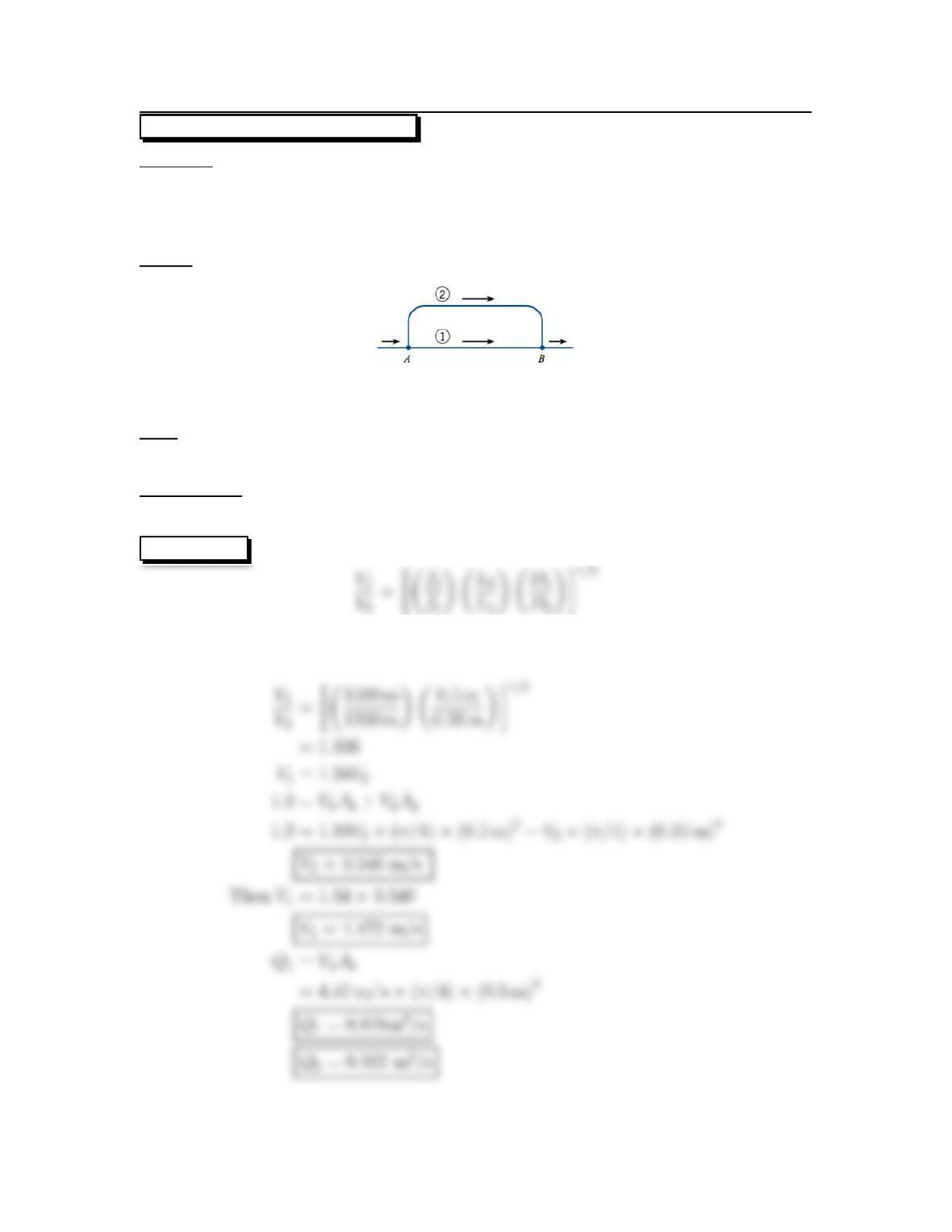
Two pipes are connected in parallel.
L1=1200m,D1=50cm,L2=1500m.
D2=35cm,Q=1.2m
3/s.
Sketch:
Find:
Division of flow of water.
Assumptions:
Friction factor, f, is equal in both lines.
SOLUTION
Initially assume f1=f2
Then
158
10.97: PROBLEM DEFINITION
Situation:
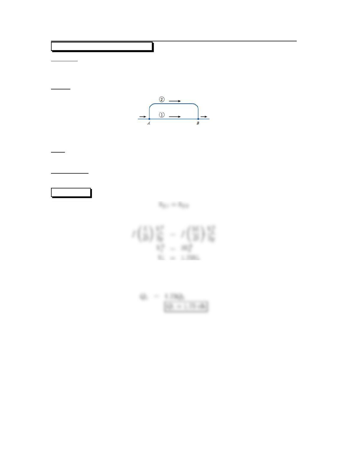
Two pipes are connected in parallel.
L2=3L1,D1=D2,Q2=1ft
3/s.
Sketch:
Find:
Dischargeinpipe1.
Assumptions:
Friction factor, f, is equal in both lines.
SOLUTION
Thus
159
10.98: PROBLEM DEFINITION
Situation:
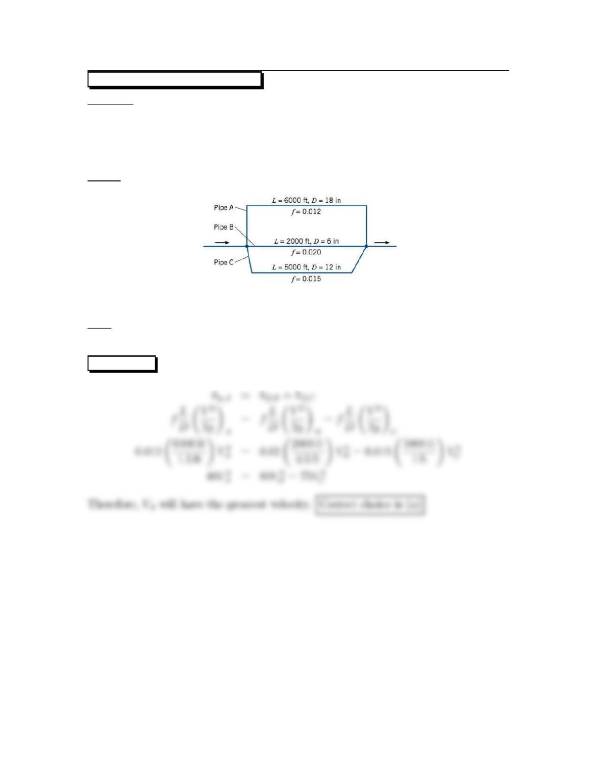
Three pipes are connected in parallel
LA= 6000 ft,DA=18in,fA=0.012.
LB=2000ft,DB=6in,fB=0.020.
LC=5000ft,DC=12in,fC=0.015.
Sketch:
Find:
Thepipehavingthegreatestvelocity.
SOLUTION
160
10.99: PROBLEM DEFINITION
f1=0.010,f2=0.012.
Find:
Ratio of discharges in two pipes.
SOLUTION
Let pipe 1 be large pipe and pipe 2 be smaller pipe. Then
161
10.100: PROBLEM DEFINITION
Situation:
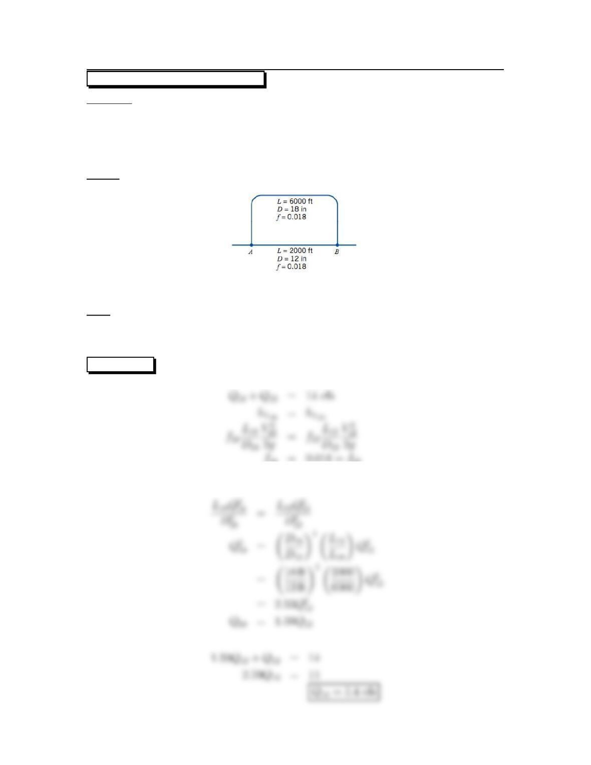
Two pipes are connected in parallel.
Q=14ft
3/s,L1=6000ft.
D1=18in,f1=0.018.
L1=2000ft,D1=12in,f1=0.018.
Sketch:
Find:
Division of flow (cfs).
Head loss (ft).
SOLUTION
f18 =0.018 = f12
so
162
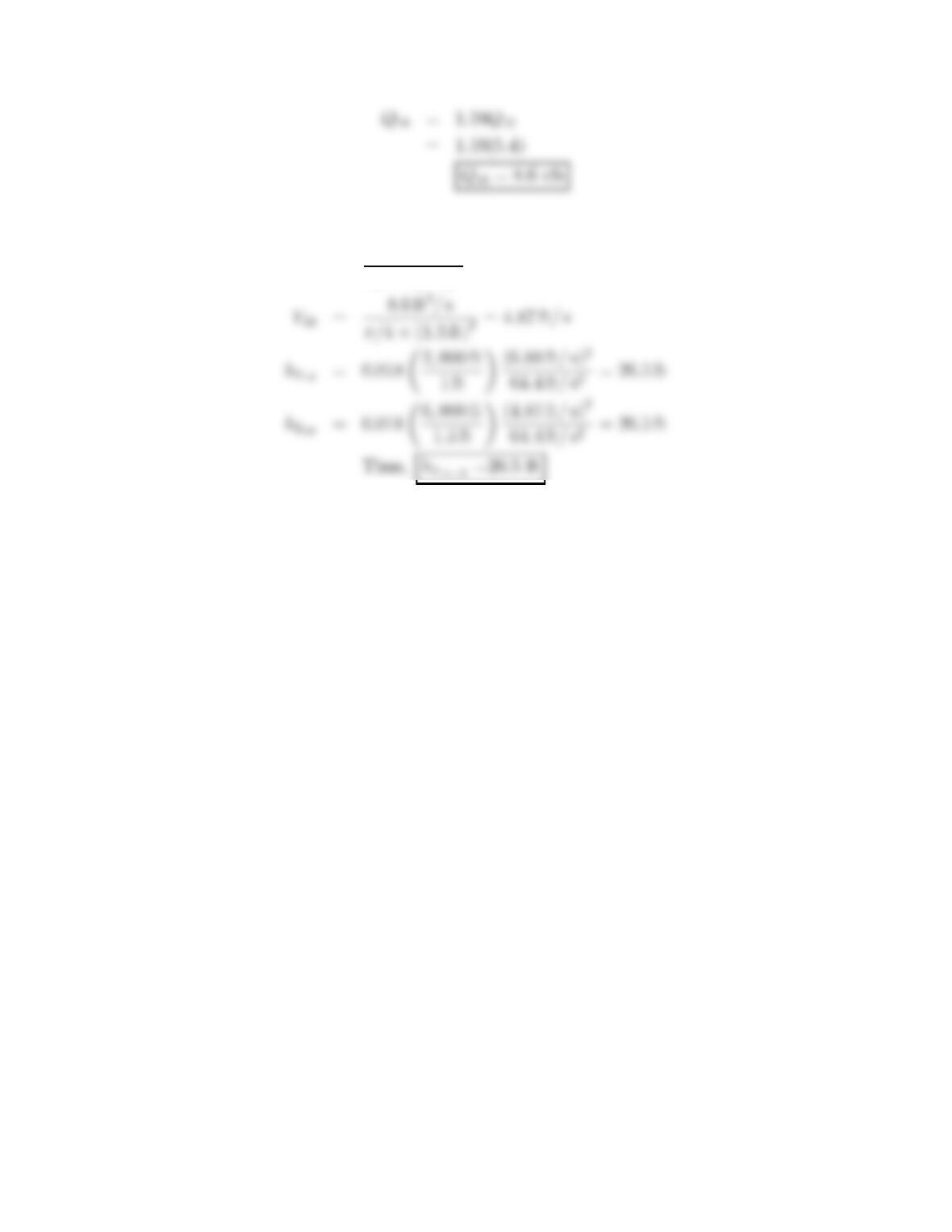
V12 =5.4ft
3/s
π/4×(1 ft)2=6.88 ft/s
163
10.101: PROBLEM DEFINITION
Situation:
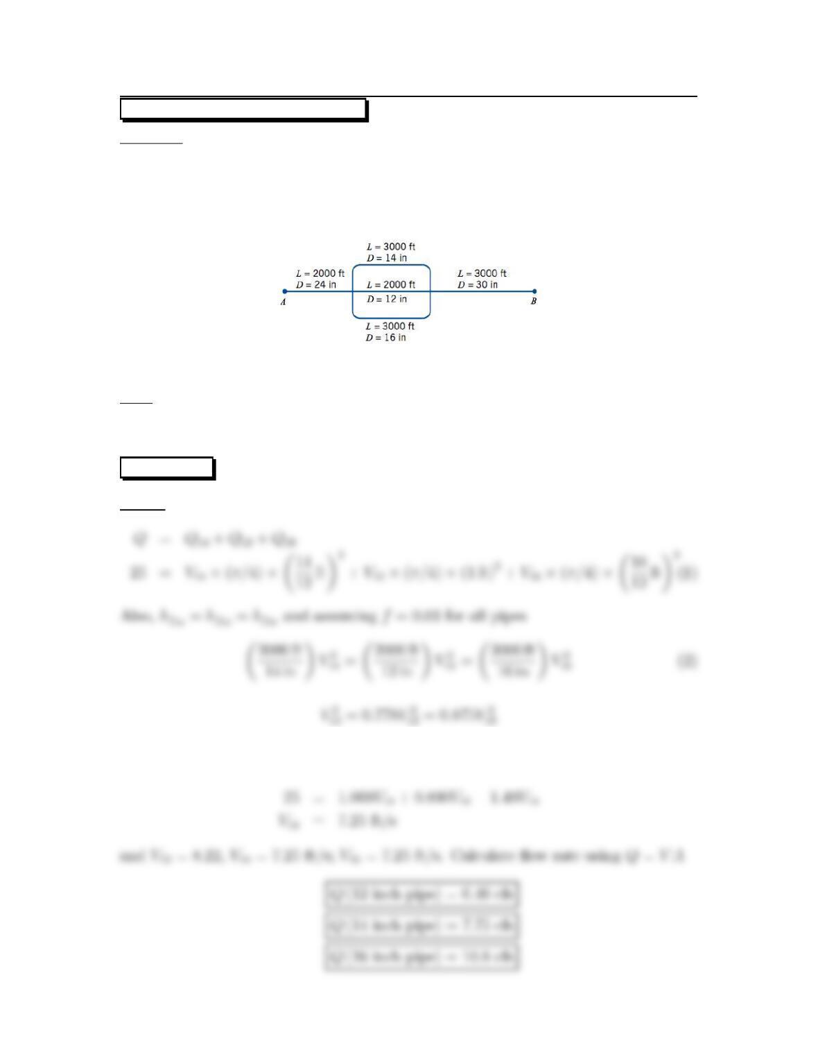
A concrete piping system is described in the problem statement.
Q=25ft
3/s,f=0.030,L24 =2000ft,D24 =24in.
L30 =3000ft,D30 =30in,L14 =3000ft,D14 =14in.
L12 =2000ft,D12 =12in,L16 =3000ft,D16 =16in.
Find:
Division of flow.
Head loss.
SOLUTION
Sketch:
From Eq.(1)
164
165
10.102: PROBLEM DEFINITION
Situation:
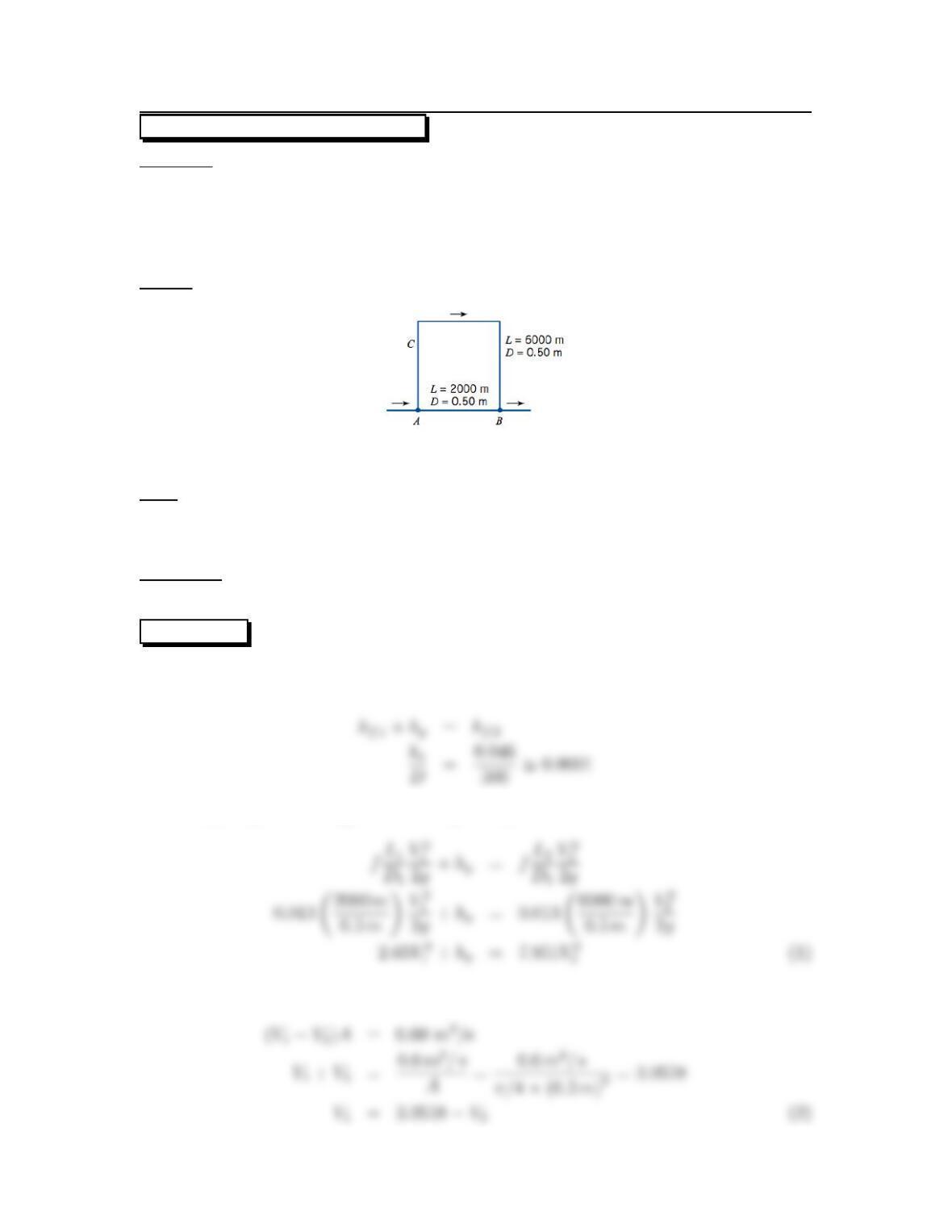
Two pipes are connected in parallel with the pump from Fig 10.20b (EFM10e) at
point C.
L1=2000m,D
1=0.50 m,L2=6000m.
D2=0.50 m,Q=0.60 m3/s.
Sketch:
Find:
Division of flow between pipes (m
3/s).
Head loss (m).
Properties:
From Table 10.4 ks=0.046 mm.
SOLUTION
Call pipe A-B pipe and pipe ACB pipe 2. Then
Assume f1=f2=0.013 (guess from Fig. 10-8)
Continuity principle
166
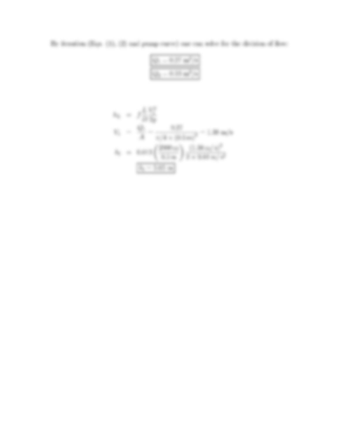
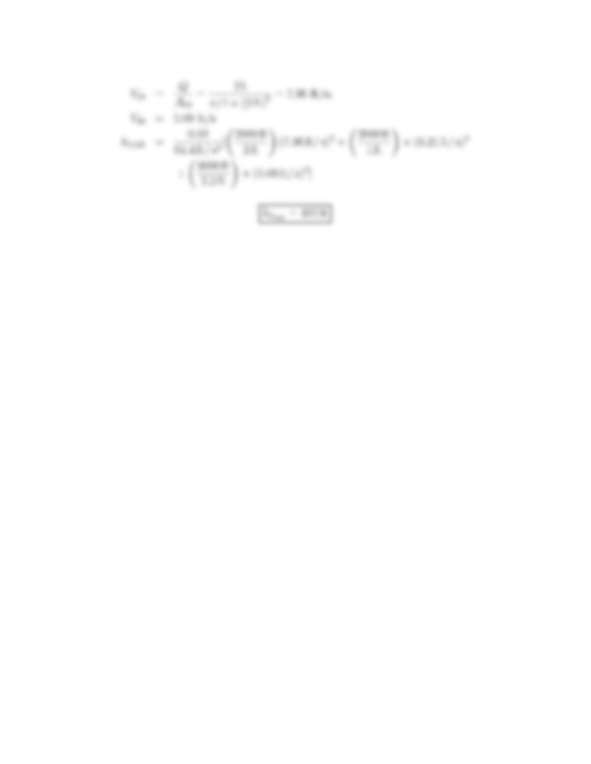
Head loss determined along pipe 1
167
10.103: PROBLEM DEFINITION
Situation:
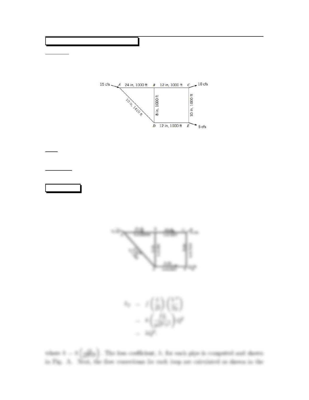
A piping network with sources and loads is specified.
f=0.012,pA=60psi, QA=15ft
3/s.
QC=10ft
3/s,QE=5ft
3/s.
Find:
Load distribution and pressure at load points.
Properties:
Water, Table A.5: γ=62.4lbf/ft3.
SOLUTION
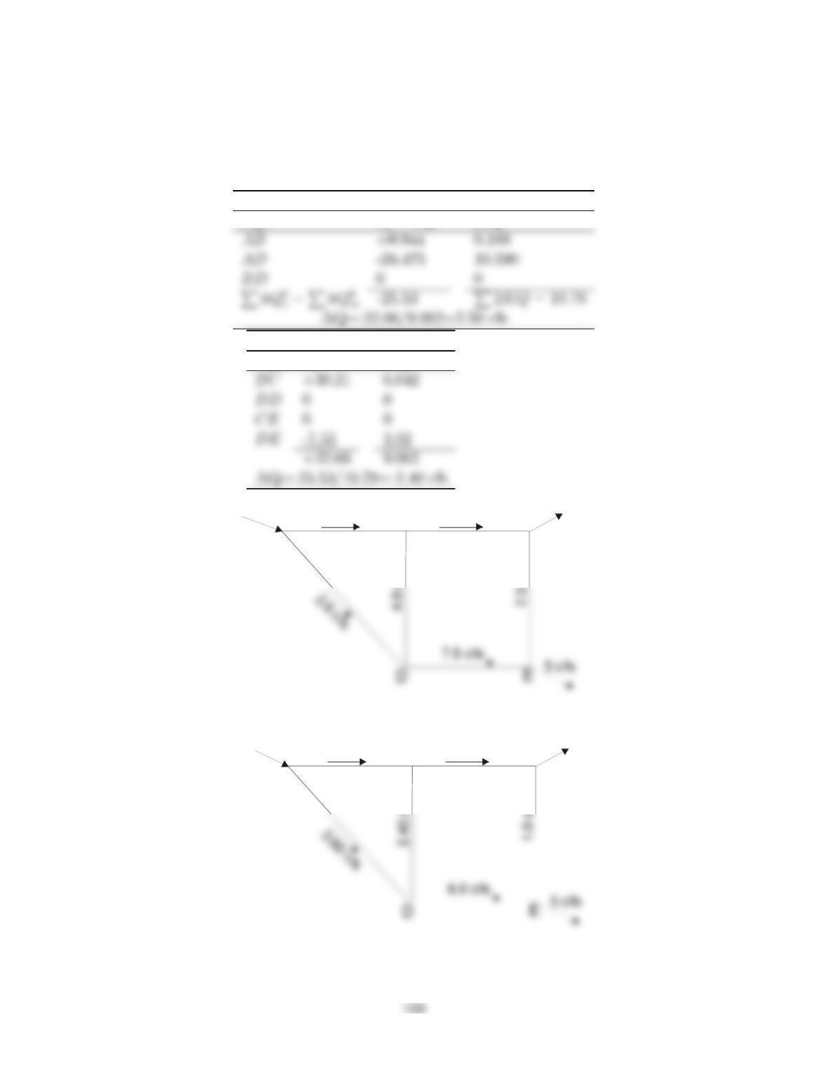
An assumption is made for the discharge in all pipes making certain that the conti-
nuity equation is satisfied at each junction. The following figure shows the network
with assumed flows.
Darcy-Weisbach equation
168
accompanying table. Since n=2(exponent on Q), nkQn−1=2kQ. When the
correction obtained in the table are applied to the two loops, we get the pipe discharges
showninFig. B. Thenwithadditionaliterations,wegetthefinal distribution of
flow as shown in Fig. C. Finally, the pressures at the load points are calculated.
Loop ABC
Pipe hf=kQ22kQ
Loop BCDE
Pipe hf2kQ
A
BC
12.4 cfs 7.5 cfs
10 cf
s
15 cfs
A
BC
11.4 cfs 9.0 cfs
10 cf
s
15 cfs
170
10.104: PROBLEM DEFINITION
Situation:
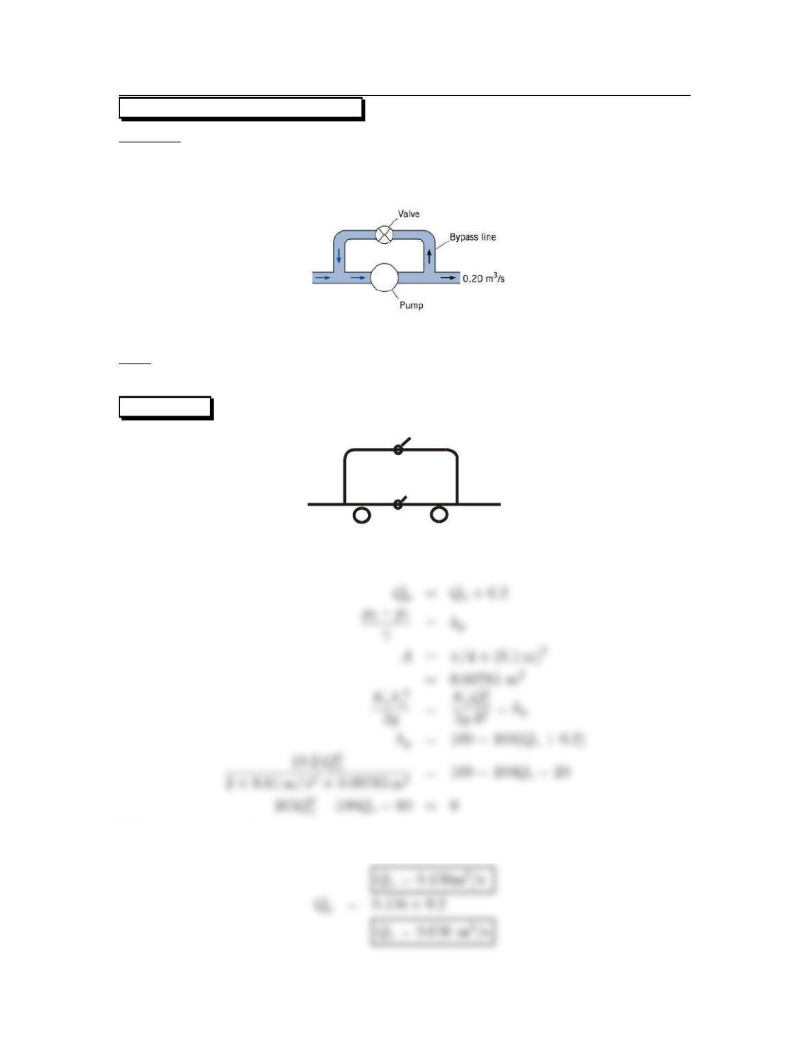
Two pipes are in parallel. One has a bypass valve and the other a pump.
hp=100−100Qp,Qp=Qv+0.2m
3/s.
Dv=10cm,Kv=0.2.
Find:
Discharge through pump and bypass line.
SOLUTION
2
1
Valve
Pump
Solve by quadratic formula
171