10-20 Compressibility and Settlement Chap. 10
Layer
H
(ft) zf
At midpoint of layer
Cc/(1+e0)C
r
/(1+e0)
δc,ult
(ft)
σ‘z0
(psf)
Δσz
(psf)
σ
‘c
(psf)
σ
‘zf
(psf)
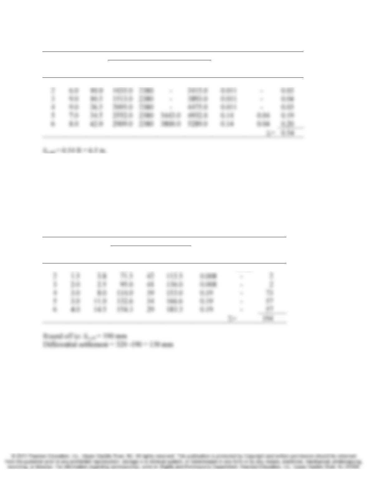
1 7.0 3.5 423.0 2380 – 2803.0 0.011 – 0.06
10.20 Using the data in Example 10.8, compute the consolidation settlement at the edge of the
tank. Then compute the differential settlement, which is the difference between the
settlement at the center and the edge.
Hint: Compute Δσz using Figure 9.13.
Solution
Use figure 9.13 to compute σz,induced
Layer
H
(m) zf
At midpoint of layer
Cc/(1+e0)C
r
/(1+e0)
δc,ult
(mm)
σ‘z0
(kPa)
Δσz
(kPa)
σ
‘zf
(kPa)
1 3.0 1.5 28.8 51 79.8 – 0.002 3
Σ
Section 10.9 Secondary Compression Settlement
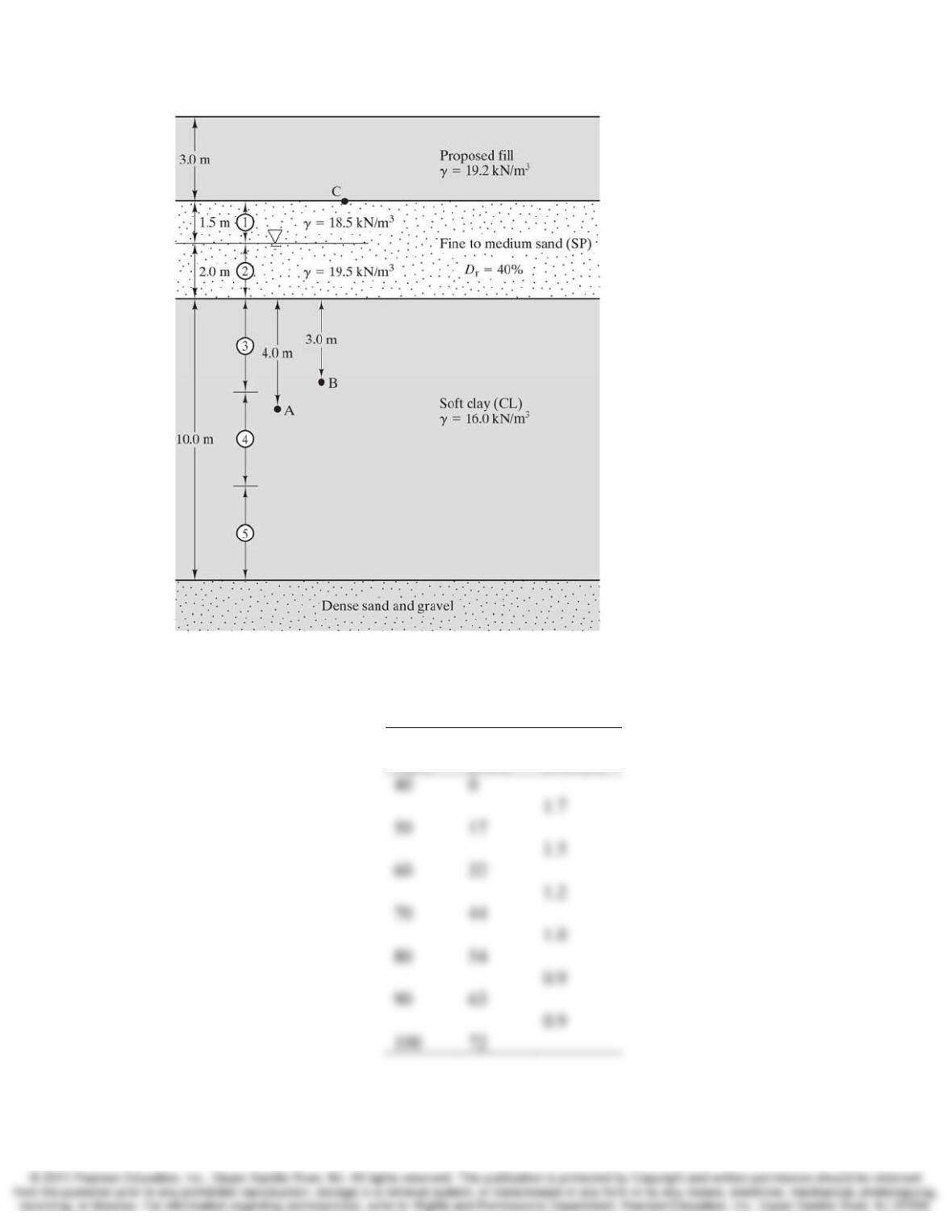
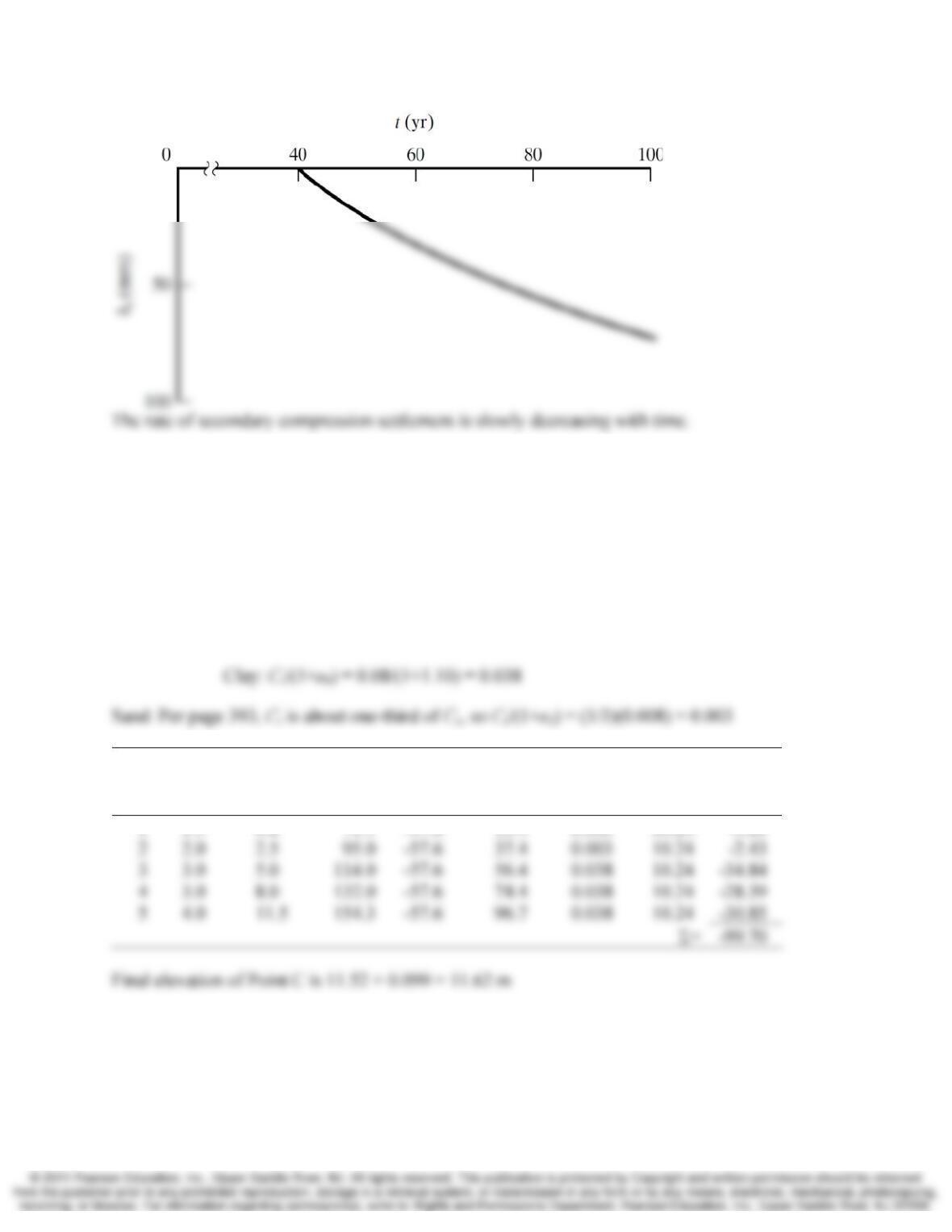
10.21 Using the data from Example 10.10, develop a plot of secondary compression settlement
vs. time for the period 40 to 100 years after completion of the fill. Is the rate of
secondary compression settlement increasing or decreasing with time?
Chap. 10 Compressibility and Settlement 10-21
Figure 10.20 Soil profile for Example 10.5
Solution
Using Equation 10.28:
t (yr)
δ
s
(mm)
δ
s/yr
(mm/yr)
10-22 Compressibility and Settlement Chap. 10
Section 10.12 Heaving Due to Unloading
10.22 Point C in Figure 10.20 was originally at elevation 12.00 m, but it dropped to elevation
11.52 m as a result of the consolidation settlement described in Example 10.5. Now that
the consolidation is complete, the fill is to be removed. Compute the new elevation of
Point C after the natural soils rebound in response to the fill removal. Ignore any
secondary compression settlement.
Solution
Layer H (m) zf
At midpoint of layer
C
r
/(1+e0) Eqn.
δc,ult
(mm)
σ‘z0
(kPa)
Δσz
(kPa)
σ
‘zf
(kPa)
1 1.5 0.8 71.5 -57.6 13.9 0.003 10.24 -3.20
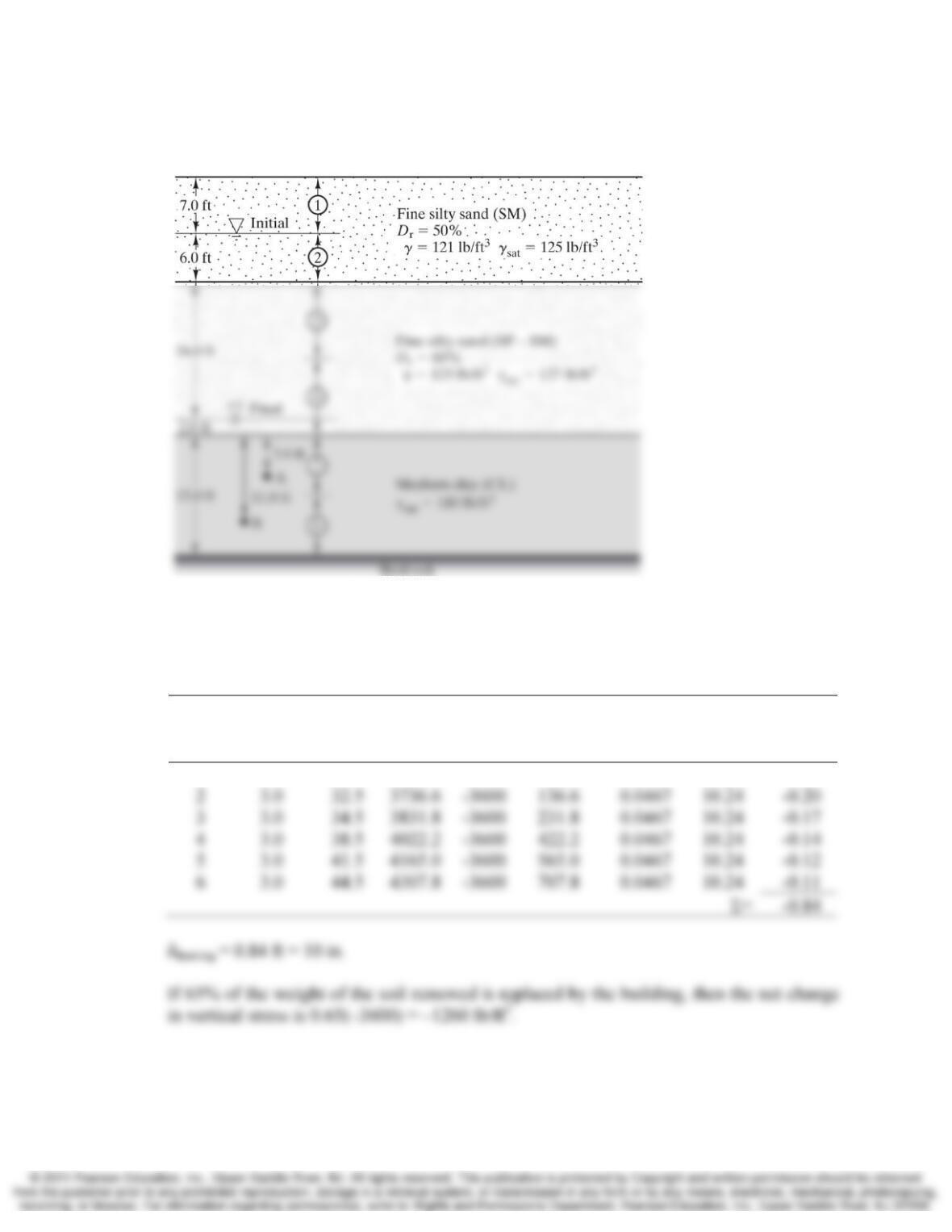
10.23 In Example 10.7 the total settlement due to the lowering of the groundwater table was
computed to be 4.6 in. It has been several years after the groundwater table was lowered
and consolidation is complete. Now the upper 30 ft of the soil profile is to be excavated
to create underground parking for a mid-rise building. How much will the base of the
excavation heave due to removal of the soil? If the total mass of the structure being
Chap. 10 Compressibility and Settlement 10-23
constructed is 65 % of the mass of the soil removed, what will be the net settlement or
heave of the structure?
Figure 10.22 Soil profile for Example 10.7
Solution
Heaving due to removal of the soil
Layer H (ft) zf
At midpoint of layer
C
r
/(1+e0) Eqn.
δc,ult
(ft)
σ
‘z0
(psf)
Δ
σz
(psf)
σ
‘zf
(psf)
1 1.0 30.5 3632.9 -3600 32.9 0.0467 10.24 -0.10
10-24 Compressibility and Settlement Chap. 10
Layer H (ft) zf
At midpoint of layer
C
r
/(1+e0)Eqn.
δc,ult
(ft)
σ‘z0
(psf)
Δ
σz
(psf)
σ
‘zf
(psf)
1 1.0 30.5 3632.9 -1260 2372.9 0.0467 10.24 -0.01
Comprehensive
10.24 A road embankment is being placed across a shallow section of a bay. The existing
profile consists of 1 m of water over a 5-m thick normally consolidated clay soil which
overlies a very dense and stiff gravelly sand. A consolidation test on the clay generated
the following results: Cc = 0.21, e0 = 1.21. The embankment material is expected to be
place at a unit weight of 18.1 kN/m3. Determine the thickness of the embankment such
that the final elevation of the embankment is 2 m above the water level. This will require
an iterative solution.
Solution
Through trial and error use 3.4 m:
Layer
H
(m) zf
At midpoint of layer
Cc/(1+e0)Eqn.
δc,ult
(m)
σ‘z0
(kPa)
Δ
σz
(kPa)
σ
‘zf
(kPa)
1 0.50 1.25 1.3 53.9 55.2 0.095 10.23 0.077
Σ
10.25 Develop a spreadsheet that can compute one-dimensional consolidation settlement due to
the weight of a fill. This spreadsheet should be able to accommodate a fill of any unit
weight and thickness, underlain by multiple compressible soil strata. It also should be
Chap. 10 Compressibility and Settlement 10-25
able to accommodate both normally consolidated and overconsolidated soils. Since the
computer does all of the computations, the spreadsheet should use at least 50 layers.
Once the spreadsheet is completed, use it to solve Examples 10.5 and 10.6. Submit
printouts of both analyses.
Solution
10.26 A cross-section through a tidal mud flat area is shown in Figure 10.24. This site is
adjacent to a bay, is subject to varying water levels according to tides, and is occasionally
submerged when heavy runoff from nearby rivers raises the elevation of the water in the
bay. For analysis purposes, use a groundwater table at the ground surface, as shown. A
crust has formed in the upper 0.8 m of soil due to dessication (drying) and is stiffer than
the underlying soil. This crust is overconsolidated case I, and the soils below are
normally consolidated. The proposed fill is required to protect the site from future
flooding, and thus permit construction of a commercial development. Use the
spreadsheet developed in Problem 10.17 to determine the ultimate consolidation
settlement due to the weight of this proposed fill. Then, consider the possibility that the
crust was not recognized in the site characterization program, and perform another
analysis using Cc /(1 + e0) = 0.20 and γ = 14.0 kN/m3 for the entire 5.0 m of clay.
Compare the results of these two analyses and comment on the importance of recognizing
the presence of crusts.
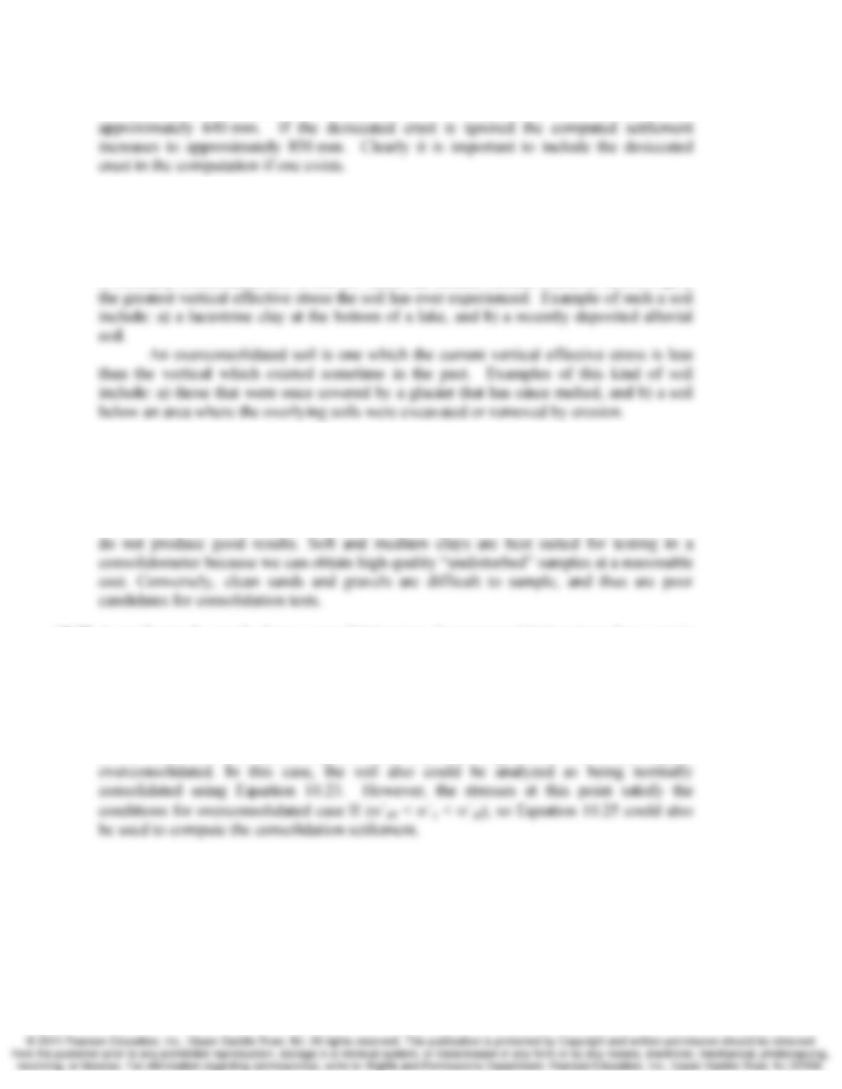
Figure 10.24 Typical crust near the ground surface in an otherwise normally
consolidated clay. el. = elevation.
Solution
10-26 Compressibility and Settlement Chap. 10
Using a spreadsheet solution the settlement accounting for the desiccated crust is
10.27 Explain the difference between normally consolidated soil and overconsolidated soils,
and give examples of geologic conditions that would form each type.
Solution
A normally consolidated soil is one for which the current vertical effective stress, σ´z0, is
10.28 What types of natural soils are best suited for testing in a consolidometer? Why? Which
are not well suited? Why?
Solution
Consolidation test results are very sensitive to the quality of the sample, so poor samples
10.29 According to the results from a consolidation test, the preconsolidation stress for a certain
soil sample is 850 lb/ft2. The in-situ vertical effective stress at the sample location is
797 lb/ft2, and the proposed load will cause σz to increase by 500 lb/ft2. Which equation
should be used to compute the consolidation settlement, 10.23, 10.24, or 10.25? Why?
Solution
In this case, σ´c is less than 20% greater than σ´z0, indicating that the soil is only slightly
10.30 A 3.0 m thick fill with a unit weight of 18.1 kN/m3 is to be placed on the soil profile
shown in Figure 10.26. Consolidation test results at Points A and B are as stated in
Problem 10.17, except that σc′ at point B is now 200 kPa. Using Equation 10.21 with Cc
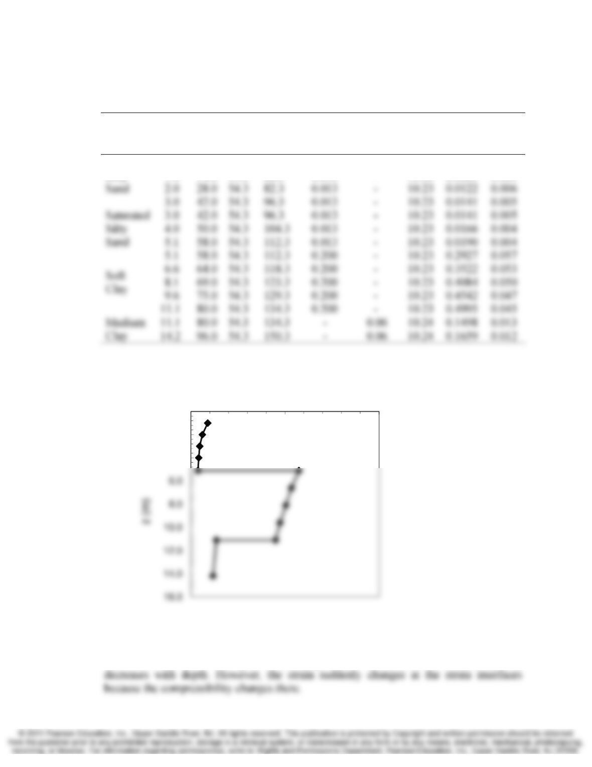
or Cr as appropriate, develop a plot of vertical strain, εz vs. depth from the original
ground surface to the top of the glacial till. How does this curve vary within a given soil
stratum? Why? Does it suddenly change at the strata interfaces? Why?
Chap. 10 Compressibility and Settlement 10-27
Solution
The soil represented by the sample from point B is now overconsolidated Case I
Layer zf
At midpoint of layer
Cc/(1+e0)C
r
/(1+e0)Eqn.
δc,ult
(m) εz
σ‘z0
(kPa)
Δσz
(kPa)
σ
‘zf
(kPa)
Silty
0.0 0.0 54.3 54.3 0.013 – 10.23 0.0000 0.000
1.0 14.0 54.3 68.3 0.013 – 10.23 0.0089 0.009
The strain decreases with depth within any given soil strata, because the ratio σ´zf/ σ´z0
0.0
2.0
4.0
0.000 0.050 0.100
εz
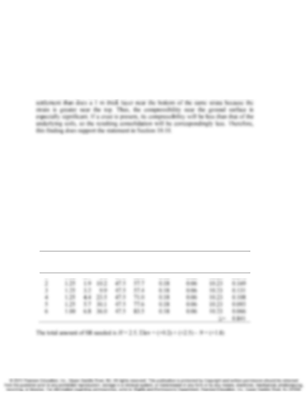
10-28 Compressibility and Settlement Chap. 10
10.31 Considering the variation of strain with depth, as found in Problem 10.30, does a 1-m
thick layer near the top of a stratum contribute more or less to the consolidation
settlement than a 1-m thick stratum near the bottom? Explain. Does this finding support
the statement in Section 10.10 that “The presence of crusts has a significant impact on
settlement computations, even if they are much thinner than the underlying compressible
soils?” Explain.
Solution
A 1 m thick layer near the top of a stratum contributes more to the consolidation
10.32 A shopping center is to be built on a site adjacent to a tidal mud flat. The ground surface
elevation is +0.2 m, and the groundwater table is at the ground surface. The underlying
soils consist of 7.3 m of medium clay with Cc /(1+e0) = 0.18, Cr /(1+e0) = 0.06, σm′ = 0,
and γ = 15.1 kN/m3. The clay stratum is underlain by relatively incompressible stiff soils.
In order to provide sufficient flood control protection, a fill must be placed on this
site before the shopping center is built, thus maintaining the entire site above the highest
flood level. This fill will have a unit weight of 19.0 lb/ft3. According to a hydrologic
study, the fill must be thick enough so that the ground surface elevation is at least +1.8 m
after all of the consolidation settlement is complete. Use the spreadsheet developed in
Problem 10.17 to determine the required ground surface elevation at the end of
construction. Assume all of the settlement occurs after construction.
Solution
This requires an iterative process, through trial and error, try H = 2.5m
Layer
H
(m)
zf
(m)
At midpoint of layer
Cc/(1+e0)C
r
/(1+e0) Eqn.
δc,ult
(m)
σ‘z0
(kPa)
Δ σz
(kPa)
σ
‘zf
(kPa)
Chap. 10 Compressibility and Settlement 10-29
10.33 A consolidation test has been performed on a sample of lodgement till from a region that
was once covered with a glacier. The current vertical effective stress at the sample
location is 1800 lb/ft2 and the measured preconsolidation stress is 32,500 lb/ft2.
(a) Assuming the glacier was in place long enough for complete consolidation to occur,
and assuming the ground surface and groundwater table elevations have remained
unchanged, compute the maximum thickness of the glacier. The specific gravity of
glacial ice is about 0.87.
(b) Although glacial ice was present for a very long time, it also extended over very large
areas, so the required drainage distance for the excess pore water was very long. As a
result, all of the excess pore water pressures may not have dissipated (Chung and
Finno, 1992). Therefore, our assumption that complete consolidation occurred may
not be accurate. If so, would our computed thickness be too large or too small?
Explain.
Solution
(a)
2
0lb/ft 30,7001,80032,500 =−=
′
−
′
=
′zcm
σσσ
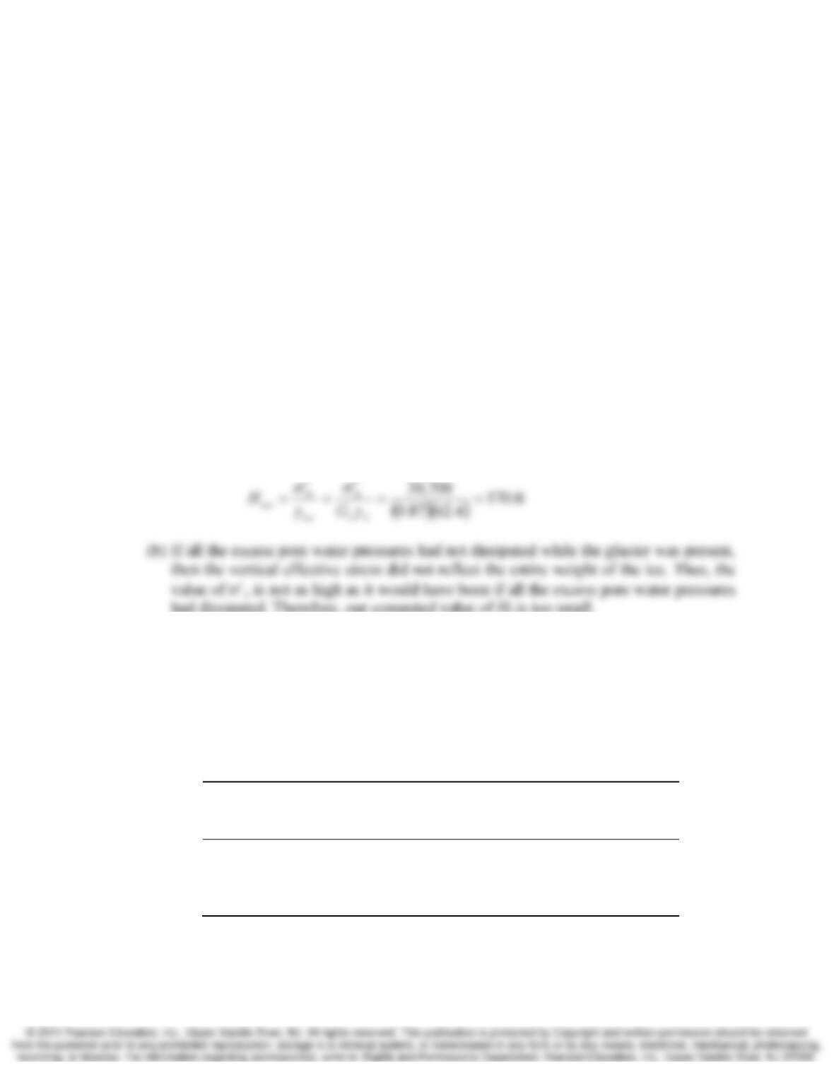
had dissipated. Therefore, our computed value of Hf is too small.
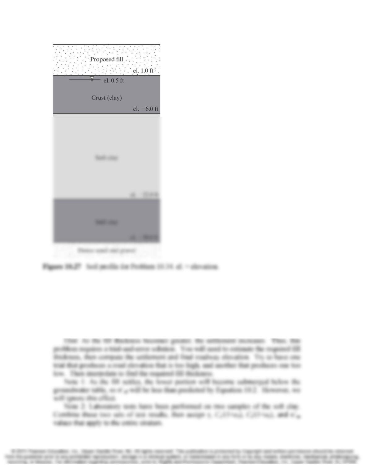
10.34 A highway is to be built across a wetlands with the soil profile shown in Figure 10.27
below. These wetlands are subject to flooding, so a fill must be placed to keep the
pavement above the highest flood level. According to a hydrologic analysis, the roadway
must be at elevation 7.0 ft or higher to satisfy this requirement. Sandy fill material that
has a compacted unit weight of 122 lb/ft3 is available from a nearby borrow site.
A subsurface exploration program has been completed at this site, and laboratory
tests have been performed. The results of this program are tabulated below:
Depth
(ft)
Dry unit
weight
(lb/ft3)
Moisture
content
(%) Cc/(1+e0) C
r
/(1+e0)
σc′
(lb/ft2)
2.0 95 28.6 0.13 0.06 3000
7.5 89 33.0 0.16 0.06 550
13.0 92 30.5 0.12 0.05 850
24.0 93 29.9 0.14 0.07 4800
All depths are measured from the original ground surface.
10-30 Compressibility and Settlement Chap. 10
The natural soils will settle under the weight of the proposed fill. Approximately
25 years will pass before this settlement is complete. Therefore, the road must be built at
an elevation higher than 7.0 ft so that after the settlement is complete it is at 7.0 ft. The
pavement thickness is 0.5 ft, so the top of the fill must remain at or above elevation 6.5 ft.
(a) Use the spreadsheet developed in Problem 10.25 to determine the required elevation
of the roadway immediately after construction. Assume that no settlement occurs
during construction, and the pavement has the same unit weight as the fill.
Chap. 10 Compressibility and Settlement 10-31
Note 3: We do not have any unit weight data for the portion of the crust above the
groundwater table. Therefore, assume it is the same as that below the groundwater
table. In this case, this assumption should introduce very little error.
(b) Is our assumption regarding the submergence of the fill (per note 1 in part a)
conservative or unconservative? Is this a reasonable assumption? Explain.
Solution
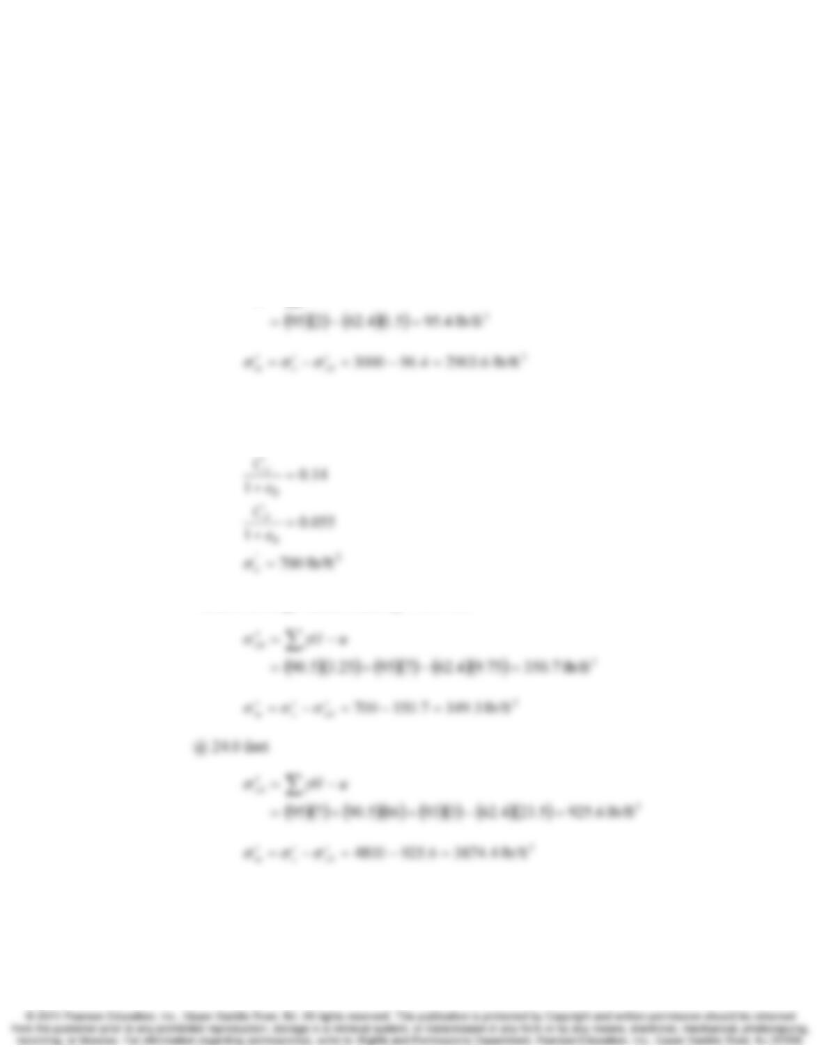
(a)
@ 2.0 feet
0
−=
′∑uH
z
γσ
Average soft clay values:
3
/5.90
=
ftlb
γ
Assume average values occur @ 10.25 feet
Through trial error use 7.25 ft
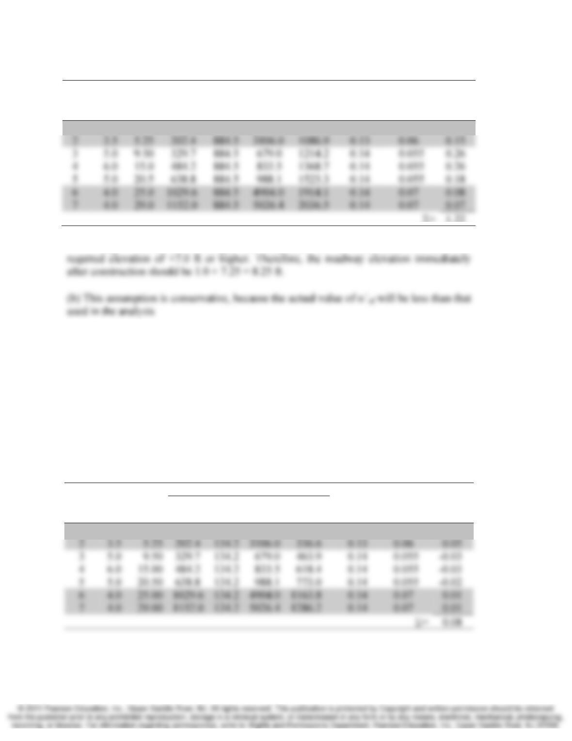
10-32 Compressibility and Settlement Chap. 10
Layer
H
(ft)
zf
(ft)
At midpoint of layer
Cc/(1+e0)C
r
/(1+e0)
δc,ult
(ft)
σ‘z0
(psf)
Δ σz
(psf)
σ
‘c
(psf)
σ
‘zf
(psf)
1 3.5 1.75 88.3 884.5 2991.9 972.8 0.13 0.06 0.22
Σ= 1.22
Hfill = 7.25 ft, this fill height will compensate for the settlement, to achieve the
10.35 An engineer has suggested an alternative design for the proposed highway in Problem
10.34. This design consists of using geofoam for the lower part of the fill, as shown in
Figure 6.45. It will be covered with at least 1.0 ft of soil to provide a buffer between the
pavement and the geofoam. Compute the minimum required geofoam thickness so that
the roadway will always be at elevation 7.0 or higher.
Hint: The geofoam is an extra “hidden” layer between the fill and the natural
ground surface with γ = 0.
Solution
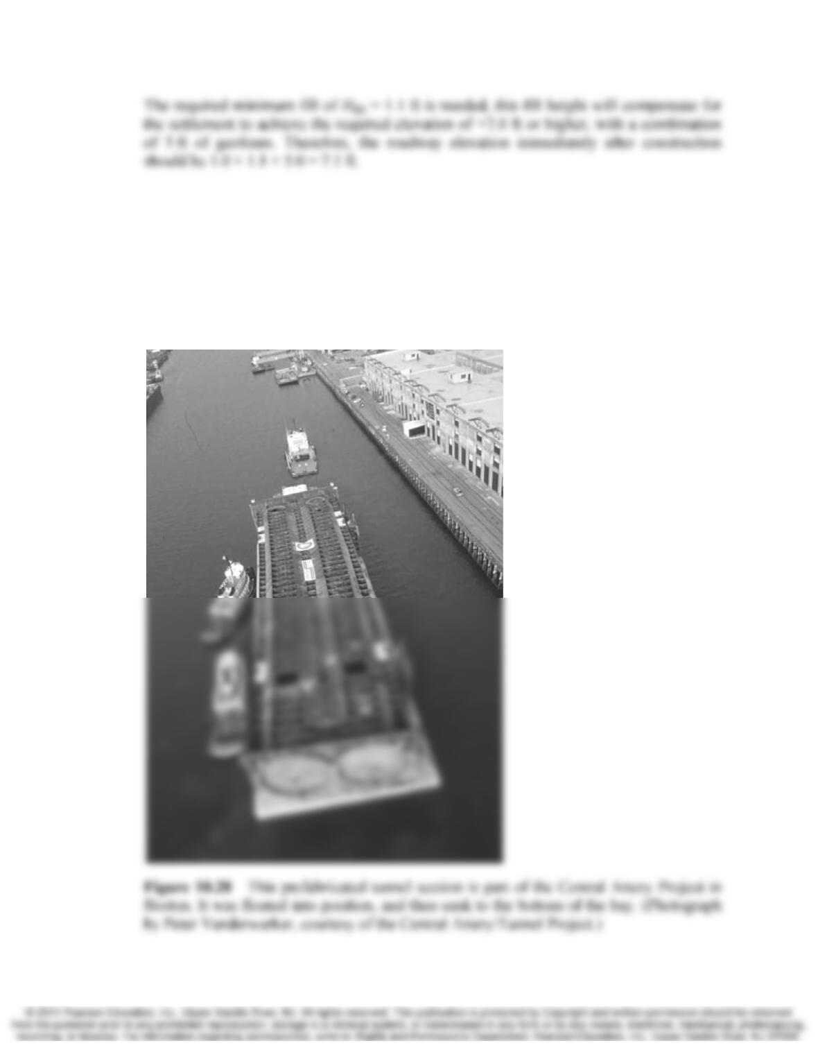
Through trial and error, use H=1.1 ft
Layer
H
(ft) zf
At midpoint of layer
Cc/(1+e0)C
r
/(1+e0)
δc,ult
(ft)
σ‘z0
(psf)
Δσz
(psf)
σ
‘c
(psf)
σ
‘zf
(psf)
1 3.5 1.75 88.3 134.2 2991.9 222.5 0.13 0.06 0.08
Chap. 10 Compressibility and Settlement 10-33
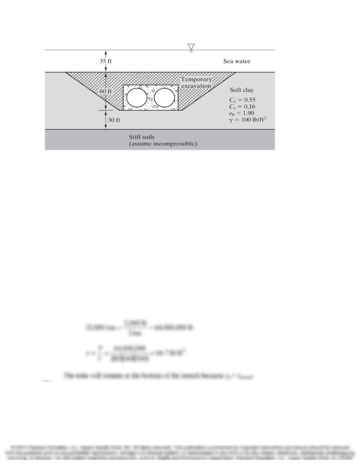
10.36 A series of prefabricated dual-bore steel tubes similar to the one in Figure 10.28 are to be
installed in an underwater trench to form a tunnel. The trench will be in seawater, which
has a unit weight of 64.0 lb/ft3. The tubes will be floated into position, and sunk into
place by temporarily flooding the interior. Then, non-structural concrete will be placed
into chambers along the tube to act as ballast, and the inside will be pumped dry. The
completed tube will be 80 ft wide, 300 ft long, and 40 ft tall, and weigh 32,000 tons
exclusive of buoyant forces. Finally, the tube will be covered with soil, producing the
cross-section shown in Figure 10.29.
10-34 Compressibility and Settlement Chap. 10
Figure 10.29 Final cross-section for underwater tunnel as described in Problem 10.36.
(a) The interior of the tube will be dewatered after the concrete is placed, but before the
trench is backfilled. Once this is done, will the tube remain at the bottom of the
trench, or will it float up to the water surface?
(b) After the trench is backfilled, what will be the net Δσz in the soft clay? Assume Δσz is
constant with depth.
(c) Using the final cross-section, compute the ultimate consolidation settlement or heave
of the tube due to Δσz′ in the soft clay. Assume no heave occurs during construction.
(d) The weakest parts of the completed tunnel will be the connections between the tube
sections. In order to avoid excessive flexural stresses at these connections, the
structural engineer has specified a maximum allowable differential settlement or
differential heave of 5 in along the length of the tube (the term “allowable” indicates
this value already includes a factor of safety). An evaluation of the soil profile
suggests the differential settlement or heave will be no more than 50 percent of the
total. Has the structural engineer’s criteria been met?
Solution
(a)
(b)
Chap. 10 Compressibility and Settlement 10-35
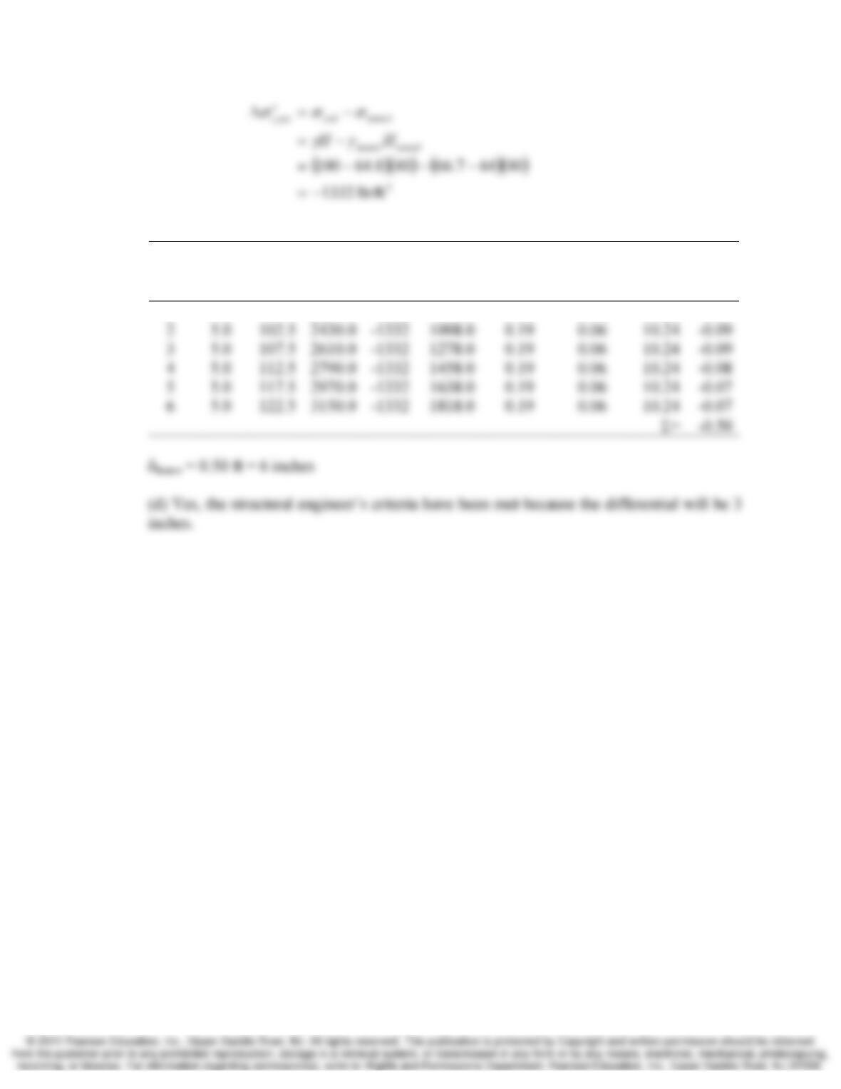
(c)
Layer
H
(ft) zf
At midpoint of layer
Cc/(1+e0)C
r
/(1+e0) Eqn.
δc,ult
(ft)
σ‘z0
(psf)
Δ
σ
z
(psf)
σ
‘zf
(psf)
1 5.0 97.5 2250.0 –1332 918.0 0.19 0.06 10.24 -0.11
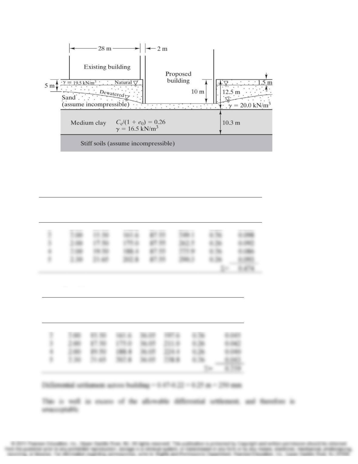
10.37 A proposed building is to have three levels of underground parking, as shown in Figure
10.30. To construct this building, it will be necessary to make a 10.0 m excavation,
which will need to be temporarily dewatered. The natural and dewatered groundwater
tables are as shown, and the medium clay is normally consolidated. The chief
geotechnical engineer is concerned that this dewatering operation may cause excessive
differential settlements in the adjacent building and has asked you to compute the
anticipated differential settlement across the width of this building. Assume the wall is
perfectly rigid, and thus does not contribute to any settlement problems, and that the
maximum allowable differential settlement from one side of the building to the opposite
side is 50 mm. Neglect any loss in σz′ below the existing building due to the removal of
soil from the excavation. Discuss the implications of your answer.
10-36 Compressibility and Settlement Chap. 10
Figure 10.30 Soil profile for Problem 10.37.
Solution
Near side:
Layer
H
(m) zf
At midpoint of layer
Cc/(1+e0)
δc,ult
(m)
σ‘z0
(kPa)
Δ
σ
z
(psf)
σ
‘zf
(kPa)
1 2.00 13.50 148.2 87.55 235.7 0.26 0.105
Far side:
Layer
H
(m) zf
At midpoint of layer
Cc/(1+e0)
δc,ult
(m)
σ‘z0
(kPa)
Δ
σ
z
(psf)
σ
‘zf
(kPa)
1 2.00 13.50 148.2 36.05 184.2 0.26 0.049
Σ
Σ
Chap. 10 Compressibility and Settlement 10-37
10.38 The Palacio de las Bellas Artes in Mexico City, shown in Figure 10.1, is an interesting
example of large consolidation settlement. It is supported on a 1.8 to 3.0 m thick mat
foundation which is approximately 65 m wide and 115 m long. The average bearing
pressure between the bottom of this mat and the supporting soil is 115 kPa (Ledesma,
1936).
The soil conditions beneath the palace are too complex to describe in detail here.
However, we can conduct an approximate analysis using the following simplified profile:
Depth
(m) Description γ
(kN/m3) 0
1e
Cc
+
0 – 5 Sandy fill 17.5 0
5 – 45 Normally consolidated soft clays 11.5 0.53
> 45 Stiff soils 0
For our simplified analysis, use a groundwater table at a depth of 5 m, and assume
the bottom of the mat is at the original ground surface. In addition, assume the fill has
been in pace for a very long time, so the consolidation settlement due to the weight of the
fill is complete.
Divide the soft clay zone beneath the center of the building into five layers of
equal thickness. Then, compute Δσz at the midpoint of each layer using the methods
described in Chapter 9. Finally, compute the ultimate consolidation settlement beneath
the center of the palace due to its own weight.
Solution
Layer
H
(m) zf
At midpoint of layer
Cc/(1+e0) Eqn.
δc,ult
(m)
σ
‘z0
(kPa)
σ
z
(kPa)
σ
‘zf
(kPa)
1 8.0 4.0 94.0 114 208.0 0.53 10.23 1.46
10.39 A fill is to be placed at a proposed construction site, and you need to determine the
ultimate consolidation settlement due to its weight. Write a 200–300 word essay
describing the kinds of field exploration, soil sampling, and laboratory testing you will
need to perform to generate the information needed for this analysis. Your essay should
describe specific things that need to be done, and what information will be gained from
each activity.
10-38 Compressibility and Settlement Chap. 10
Solution
The field exploration will need to include drilling exploratory borings at the site of the