Stress Distribution and Settlement Analysis Chapter 10
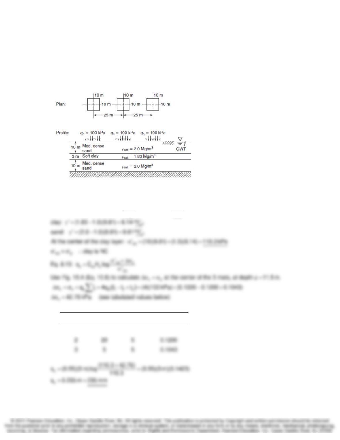
10-18. Three uniformly distributed loads of 100 kPa each are applied to 10 x 10 m square areas
on the soil profile shown in Fig. P10.18. Undisturbed samples of the clay were taken prior to
construction, and consolidation tests indicated that the average preconsolidation stress is about
110 kPa, the average compression index is 0.50, and the average recompression index is 0.02.
Estimate the total consolidation settlement for the clay layer only under the center of the middle
loaded area.
SOLUTION:
oo
cr p
q100kPa,assumee0.9
0.50 0.02
consolidation indices: C 0.55, C 0.022, ‘ 110 kPa
0.9 0.9
εε
==
== == σ=
Rectangle x y I
1 30 5 0.1226
Stress Distribution and Settlement Analysis Chapter 10
10-19. A series of oil storage tanks are to be constructed near Mystic River power station in
Boston, MA. The typical tank is 22 m in diameter, and it exerts an average foundation stress of
about 125 kPa. The soil profile at the site is very similar to that shown in Fig. 8.19(a), see next
page. Estimate both the total and differential consolidation settlement under the average tank.
SOLUTION:
pvo v
cor c
vo p
‘‘
Eq. 8.19b: s H C log C log
”
Calculate settlement of the silt and clay layers from depth 7 to 32 m.
Break region into 4 sublayers.
εε
⎡⎤
σσ+Δσ
=+
⎢⎥
σσ
⎢⎥
⎣⎦
∑∑
…………………………….………………………………….………………………………….…….
s
s
oo
…..
Assume G 2.7
Gw (2.7)(0.3)
Estimate e for the upper organic and silty layers. e 0.81
=
== =
o
v
See table below for values determined from Fig. 10.5.
Δσ
Depth below
tank (z), m z/r Icenter
Δσcenter
(kPa) Icenter
Δσcenter
(kPa)
10 0.91 0.696 87.0 0.35 43.8
solution continued on next page

Stress Distribution and Settlement Analysis Chapter 10
10-19 continued.
Table below summarizes consolidation settlement calculation for the tank center.
10-19: Tank Center
Depth Below Clay Surface σ‘
vo
σ‘
p
Δσ
v
σ‘
vf
Compression Ratio Change in
Sublayer Effective Preconsol. Pressure Final Recomp. Virgin Thickness
Top Bottom Center of Thickness Overburden Pressure Change Pressure Curve Curve
Δ
H
Sublayer H
o
Pressure C
ε
r
C
ε
c
(m) (m) (m) (m) (kPa) (kPa) (kPa) (kPa) (m)
0.0 6.0 3.00 6.00 8.93 80.00 87.0 95.88 0.191 0.0191 1.1003
Table below summarizes consolidation settlement calculation for the tank edge.
10-19: Tank Edge
Depth Below Clay Surface σ‘
vo
σ‘
p
Δσ
v
σ‘
vf
Compression Ratio Change in
Sublayer Effective Preconsol. Pressure Final Recomp. Virgin Thickness
Top Bottom Center of Thickness Overburden Pressure Change Pressure Curve Curve
Δ
H
Sublayer H
o
Pressure C
ε
r
C
ε
c
(m) (m) (m) (m) (kPa) (kPa) (kPa) (kPa) (m)
0.0 6.0 3.00 6.00 8.93 80.00 43.8 52.73 0.191 0.0191 0.8838
10-19. Solution Summary
Total maximum consolidation settlement = 389 mm
Differential settlement = 389 – 351 = 38 mm
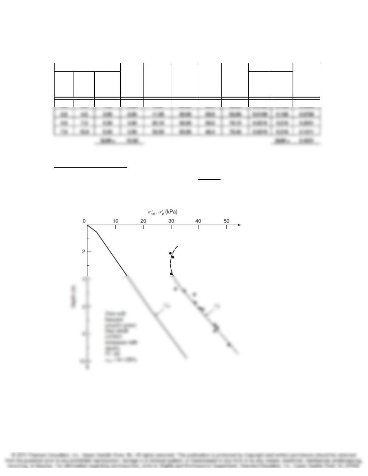
10-20. A new highway to Siracha, Thailand, is to be constructed east of Bangkok, across a
region of deep deposits of very soft marine clay. A typical soil profile is shown in Fig. 8.21(a). The
average Cc = 0.8 below the drying crust. The proposed embankment is 17 m wide at the top, has
three horizontal to one vertical side slope, and is 2.5 m high. Estimate the ultimate consolidation
settlement of the centerline of the embankment.
SOLUTION:
pvo v
cor c
vo p
‘‘
Eq. 8.19b: s H C log C log
”
Calculate settlement of the silt and clay layers from depth 0 to 10 m.
εε
⎡⎤
σσ+Δσ
=+
⎢⎥
σσ
⎢⎥
⎣⎦
∑∑
…
s
o
…………………………………………………………………….………………………………….….
Assume G 2.7, w 15% (upper crust)
Estimate e for the lower green clay sublayers
==
s
o
Gw (2.7)(1.0)
. e 2.7
S1.0
== =
z below
embankment
(m) a/z b/z I
Δσv = 2σz
(kPa)
1 7.5 17 0.499 50.9
solution continued on next page
Stress Distribution and Settlement Analysis Chapter 10
10-20 continued.
10-20: Embankment Center
Depth Below Clay Surface σ‘
vo
σ‘
p
Δσ
v
σ‘
vf
Compression Ratio Change in
Sublayer Effective Preconsol. Pressure Final Recomp. Virgin Thickness
Top Bottom Center of Thickness Overburden Pressure Change Pressure Curve Curve
Δ
H
Sublayer H
o
Pressure C
ε
r
C
ε
c
(m) (m) (m) (m) (kPa) (kPa) (kPa) (kPa) (m)
0.0 2.0 1.00 2.00 5.30 34.00 50.9 56.20 0.0108 0.108 0.0646
10-20. Solution Summary
Consolidation settlement at embankment center = 423 mm
Stress Distribution and Settlement Analysis Chapter 10
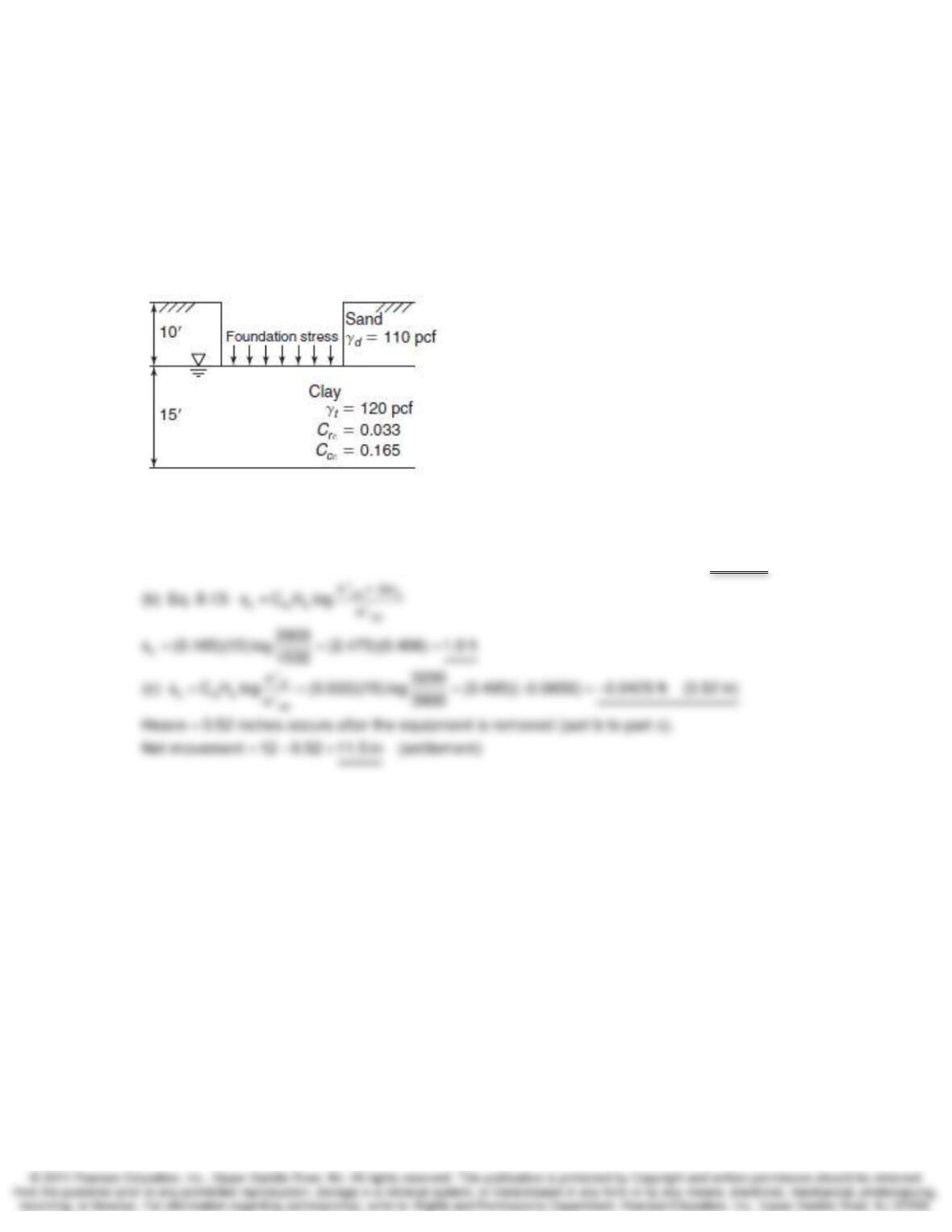
10-21. Figure P10.21 shows a proposed foundation site, with 10 ft of sand overlying 15 ft of clay
with consolidation properties shown. The clay is normally consolidated. Assume 1-D conditions.
(a) Compute the initial
σ
’v at the middle of the clay layer prior to excavation and construction. (b)
After excavation and during construction, the foundation area will be heavily loaded with the
structure and equipment so that
σ
’v at the middle of the clay layer will be increased to 3900 psf.
Determine the settlement that will occur under these conditions. (c) After construction is
completed, the equipment will be removed, and the final
σ
’v at the middle of the clay layer will be
3200 psf.
SOLUTION:
vo
(a) At the center of the clay layer: ‘ (10 ft)(110 pcf ) (7.5 ft)(120 62.4 pcf) 1532 psf
σ= + − =
Stress Distribution and Settlement Analysis Chapter 10
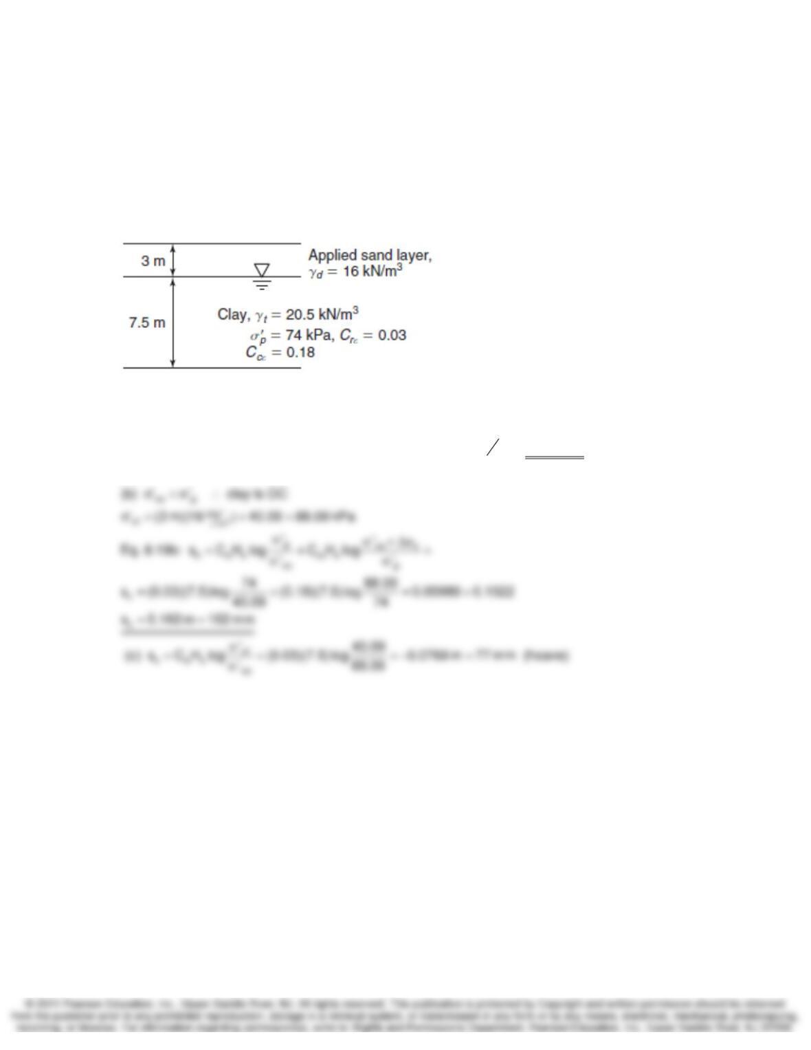
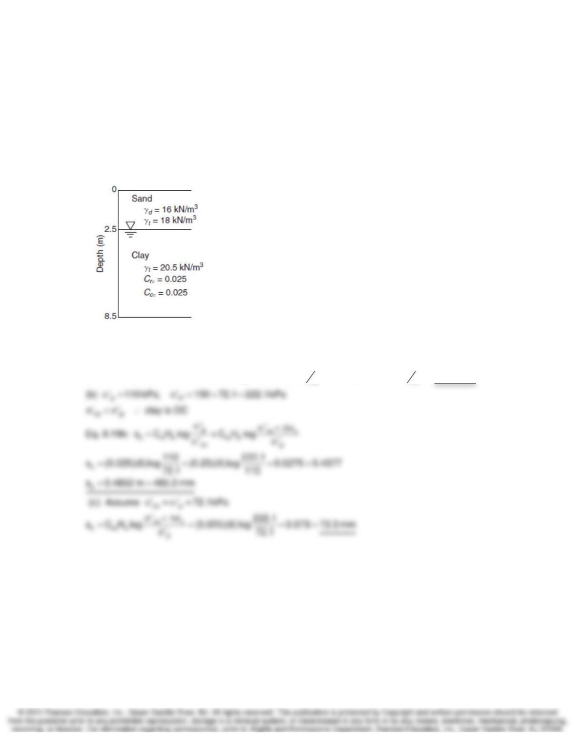
10-22. As part of a construction project, a 7.5 m thick layer of clay is to be loaded with a
temporary 3 m thick sand layer. The figure below shows the water table location, soil unit weights,
and the compression curve properties for the clay. Assume the sand layer remains dry. (a)
Calculate the value of
σ
’v in the middle of the clay layer (at 3.75 m below the water table) before
the sand layer is applied, and after consolidation is complete. (b) Based on your answer in part
(a), and the compression curve characteristics, calculate the settlement that will occur under
these conditions. (c) How much will the clay layer heave when the 3 m sand layer is removed?
SOLUTION:
3
kN
vo m
p
(a) At the center of the clay layer: ‘ (3.75 m)(20.5 9.81 ) 40.09 kPa
‘74kPa
σ= − =
σ=
Stress Distribution and Settlement Analysis Chapter 10
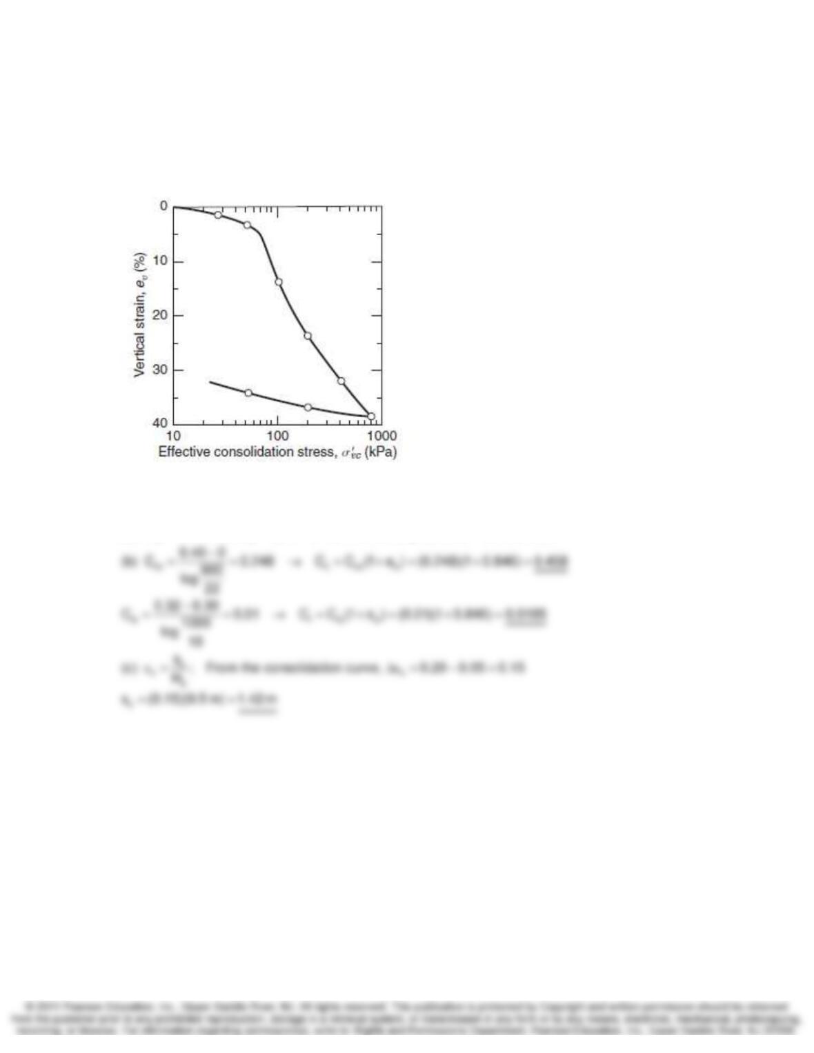
10-23. The figure shows the 1-D compression curve for a clay. (a) Using log interpolation
between 100 and 1000, determine the
σ
’v value at a vertical strain,
ε
v = 20%. (b) If the initial void
ratio, eo = 0.846, determine Cr and Cc for this soil. For Cc, use the portion of the curve between
σ
’v
= 200 and 800 kPa. (c) If the original clay layer thickness is 9.5 m, determine the settlement that
occurs in the layer when it is loaded from 70 to 200 kPa.
SOLUTION:
vv
(a) ‘ 140 kPa at 20% ( 60% of the way between 100 and 200)
σ= ε=
∼
Stress Distribution and Settlement Analysis Chapter 10
10-24. A large embankment is to be built on the surface of a 15-ft clay layer. Before the
embankment is built, the initial
σ
’v at the middle of the clay layer is 480 psf. The results from a 1-D
consolidation test on the clay from the middle of the layer are as follows:
σ
’p = 1800 psf, Cr
ε
=
0.0352, Cc
ε
= 0.180. If the final
σ
’v at the middle of the layer after the embankment loading is
2100 psf, what is the settlement, in inches, of the clay layer resulting from this loading?
SOLUTION:
vo p
At the center of the clay layer: ‘ 480 kPa, ‘ 1800 kPa
σ= σ=
Stress Distribution and Settlement Analysis Chapter 10
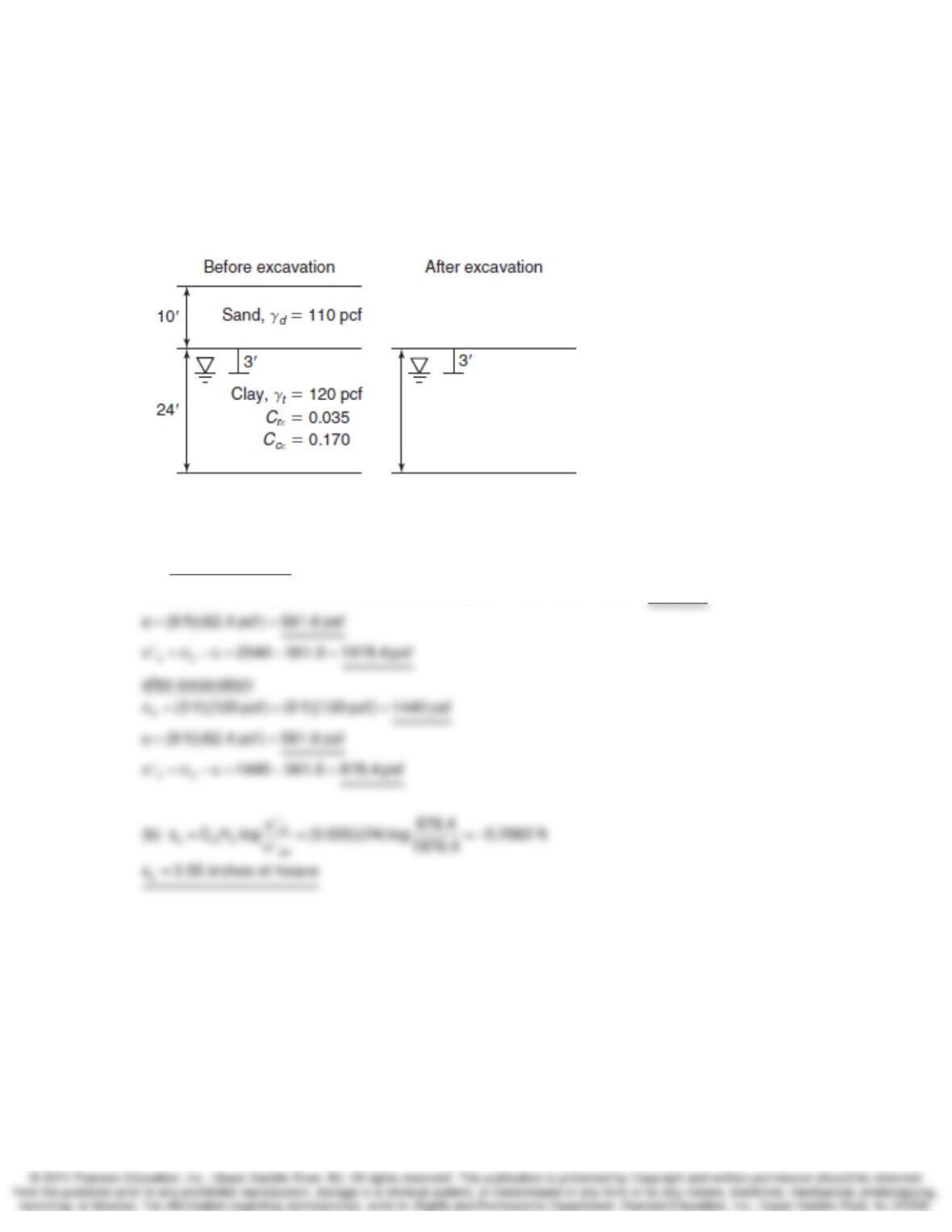
10-25. The figure shows a proposed site where an excavation will be made. The 10 ft layer of
sand will be removed, so that the top of the 24 ft. normally consolidated clay layer will be
exposed. Assume full capillarity in the clay only. (a) Assume that the water table location remains
the same during excavation. Compute the
σ
v,
σ
’v and u values at the middle of the clay layer
before and after the excavation. (b) Assuming 1-D conditions, compute how much the clay layer
will deform due to this excavation, in inches. Specify whether this is settlement or heave.
SOLUTION:
v
(a) before excavation
(10 ft)(110 pcf) (3 ft)(120 pcf) (9 ft)(120 pcf ) 1100 360 1080 2540 psf
σ= + + = + + =
Stress Distribution and Settlement Analysis Chapter 10
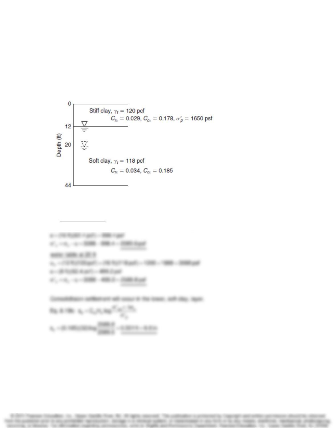
10-26. The figure shows the soil profile at a site where you plan to lower the water table. You
have results from two consolidation tests, one from the upper 12 ft thick overconsolidated crust,
and another from the lower 32 ft thick normally consolidated zone. You plan to lower the water
table from its current 12 ft depth to 20 ft below ground surface. The consolidation properties for
each layer are shown. Assume full capillarity. (a) Compute
σ
’v the in the middle of each layer
before and after the water table is lowered. (b) Determine the total settlement that will result from
lowering the water table.
SOLUTION:
v
(a) water table at 12 ft
(12 ft)(120 pcf) (16 ft)(118 pcf) 1200 1888 3088 psf
σ= + = + =

Stress Distribution and Settlement Analysis Chapter 10
10-27. When a consolidation test is performed on some soils, the virgin compression region is
not linear, but bilinear. The figure shows such a compression curve from a 15 ft thick layer. (a)
What vertical strain,
ε
v, occurs when the soil is loaded from an initial
σ
’v1 = 560 psf to
σ
’v2 = 3000
psf? (b) If you load the soil further, to
σ
’v3 = 4000 psf, how much additional settlement occurs?
(c) Finally, if you unload from 4000 psf back to
σ
’v4 =3000 psf, what additional deformation (in
feet) occurs?
SOLUTION:
vf
vi
vi
‘980 3000
(a) C log (0.032)log (0.17)log
‘560980
⎡⎤
σ
ε= = +
⎢⎥
σ
⎣⎦
∑
Stress Distribution and Settlement Analysis Chapter 10
10-28. The figure shows a soil profile where a clay layer will consolidate under an embankment
loading of 150 kPa. There is no capillarity. Your firm performed two consolidation tests: i) one
test indicated that the soil is overconsolidated, with
σ
’p = 110 kPa. ii) one test indicated that the
soil is normally consolidated. Both tests gave the same Cr
ε
and Cc
ε
values. Assume Cc
ε
= 0.25.
(a) Determine the initial
σ
’v at the middle of the clay layer (i.e., at depth 5.5 m). (b) Compute the
settlement due to the embankment loading, assuming that the overconsolidated assumption is
correct (
σ
’p = 110 kPa). (c) Compute the settlement again, this time assuming that the soil is
normally consolidated.
SOLUTION:
33
kN kN
vo mm
(a) At the center of the clay layer: ‘ (2.5 m)(16 ) (3 m)(20.5 9.81 ) 72.07 kPa
σ= + − =