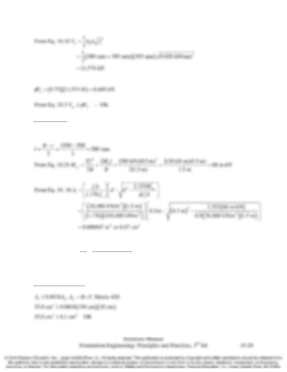
Chap. 10 Spread Footings-Structural Design
Check flexural
Find the required steel area
( )( )
2
6.07 cm
From Eq. 10.17 0.0013
150 cm 30 cm
s
A
bd
r
= = =
, NOT OK min. steel ratio is 0.0018
Try 7 #25 bars (As= 35.0 cm2)
Check minimum steel
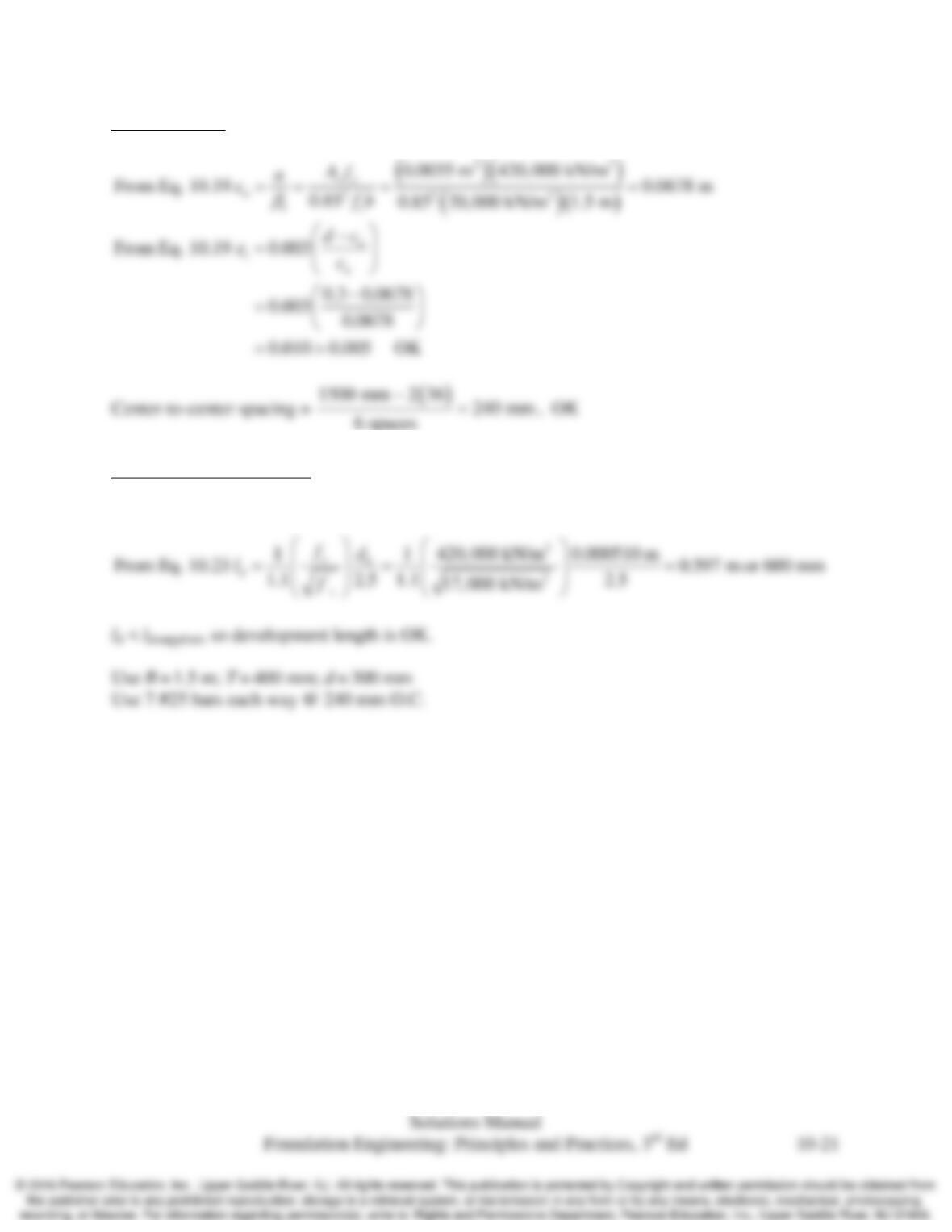
Chap. 10 Spread Footings-Structural Design
Check ductility
Check development length
,supplied
From Eq. 10.25 70 mm 500 mm 70 mm 430 mm
d
ll=-= -=
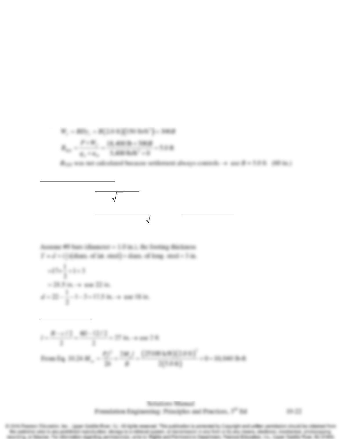
Chap. 10 Spread Footings-Structural Design
10.12 A 12–in wide concrete block wall carries an unfactored vertical design load of 25.1 k/ft. The
sustained vertical load for serviceability analysis is 18.4 k/ft. It is to be supported on a
continuous footing made of 2500 lb/in2 concrete and 40 k/in2 steel. The soil has an allowable
bearing pressure for bearing capacity of 6700 lb/ft2 (using ASD methods) and an allowable
bearing pressure for settlement of 4000 lb/ft2. The groundwater table is at a great depth. The
local building code requires that the bottom of this footing be at least 24 inches below the ground
surface. Determine the required footing width, thickness, and design the lateral and longitudinal
steel. Show your design in a sketch.
Solution
Per problem statement use D = 24 in. = 2 ft.
Compute required thickness
( )( )
( )( )( ) ( )( )
‘
2
()
From Eq. 10.27
48 2
25,100 lb/ft. 60 in. 12 in.
48 0.75 12 in. 2500 lb/in 2 25,100 lb/ft
17 in.
u
wc u
PB c
d
bf P
φ
–
=+
–
=+
=
Design lateral steel
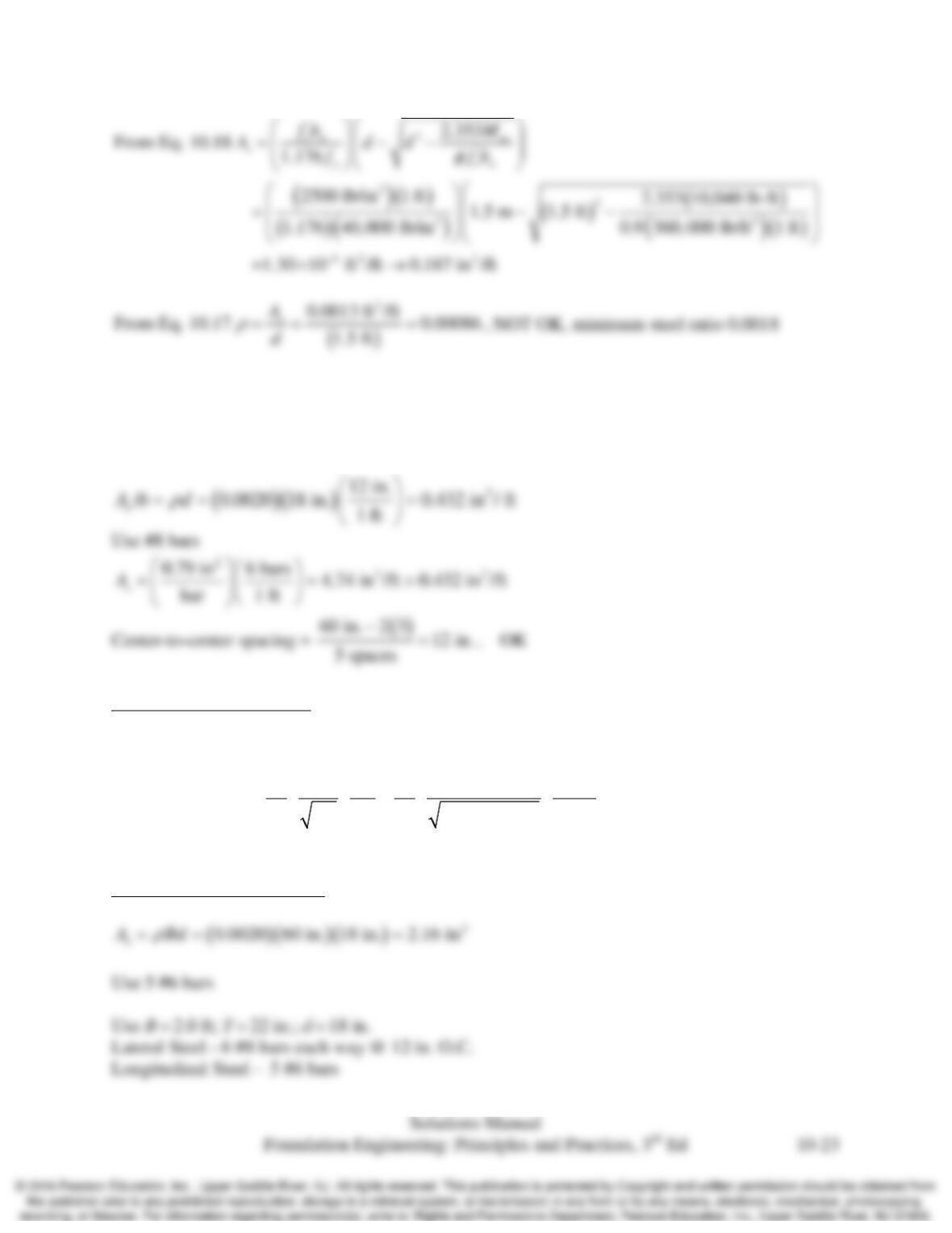
Chap. 10 Spread Footings-Structural Design
Use Grade 40,
min
r
= 0.0020
min min
use
rr r
<∴
Check development length
,supplied
From Eq. 10.25 3 in 24 in. 3 in. 21 in.
d
ll=-= –=
2
2
40,000 kN/m 1.0in.
From Eq. 10.23 24 in.
40 2.5 40 2.5
2,500 kN/m
33
yb
d
c
fd
l
f′
= = =
ld < ld,supplied, so development length is OK.
Design the longitudinal steel
Chap. 10 Spread Footings-Structural Design
10.13 A 200-mm wide concrete block wall carries a factored vertical design load of 172 kN/m. The
sustained load for settlement is 130 kN/m. It is to be supported on a continuous footing made of
18 MPa concrete and 280 MPa steel. The soil has an allowable bearing pressure for bearing
capacity of 180 kPa (using LRFD methods) and an allowable bearing pressure for settlement of
110 kPa. The groundwater table is at a great depth. The local building code requires that the
bottom of this footing be at least 500 mm below the ground surface. Determine the required
footing width, thickness, and design the lateral and longitudinal steel. Show your design in a
sketch.
Solution
Per problem statement use D = 500 mm
( )( )
( )( )( ) ( )( )
‘
1500 ( )
From Eq. 10.27
500 3
(1500) 172 kN/m 1300 mm 200 mm
500 0.75 1000 mm 18 MPa 3 172 kN/m
250 mm
u
wc u
PB c
d
bf P
φ
–
=+
–
=+
=
Assume metric #13 bars (diameter = 1.0 in.), the footing thickness
Design lateral steel
Chap. 10 Spread Footings-Structural Design
Check development length
,supplied
From Eq. 10.25 75 700 mm 75 mm 625 mm
d
ll=-= – =
1 1 280 MPa 12.7 mm
From Eq. 10.23 304 mm
1.1 2.5 1.1 2.5
18 MPa
yb
d
c
fd
l
f
′
= = =
ld < ld,supplied, so development length is OK.
Design the longitudinal steel:
Chap. 10 Spread Footings-Structural Design
10.14 An 18-inch square concrete column carries a factored ultimate compressive load of 640 k. It is
to be supported on a 8 ft wide 12 ft long rectangular spread footing. Select appropriate values
for
c
f′
and fy, then determine the required footing thickness and design the flexural reinforcing
steel. Show the results of your design in a sketch.
Solution
Chosen values are
c
f′
= 3,000 lb/in2 and fy = 60,000 lb/in2
Check two way shear
( ) ( )
( )
22
2
33
24
2
2
96 in. 18 in. 26 in.
640,000 lb 0
496 in.
1
() ()
From Eq. 1
26,400 l
.9 4
b
0u
uc u
PB cd B cd
VM
BB
-+ -+
=
-+
= +
+
=
Check one way shear
( )
2
2
2
3
2
From Eq. 10.13 1
22
uu
uc
cd
PM
Bc d
VB BB
+
—
= +-
Chap. 10 Spread Footings-Structural Design
Longitudinal steel
144 18 63 in.
22
Bc
l—
= = =
( )( )
2
6.48 in 0.0080
44 in 18 in
s
A
bd
r
= = =
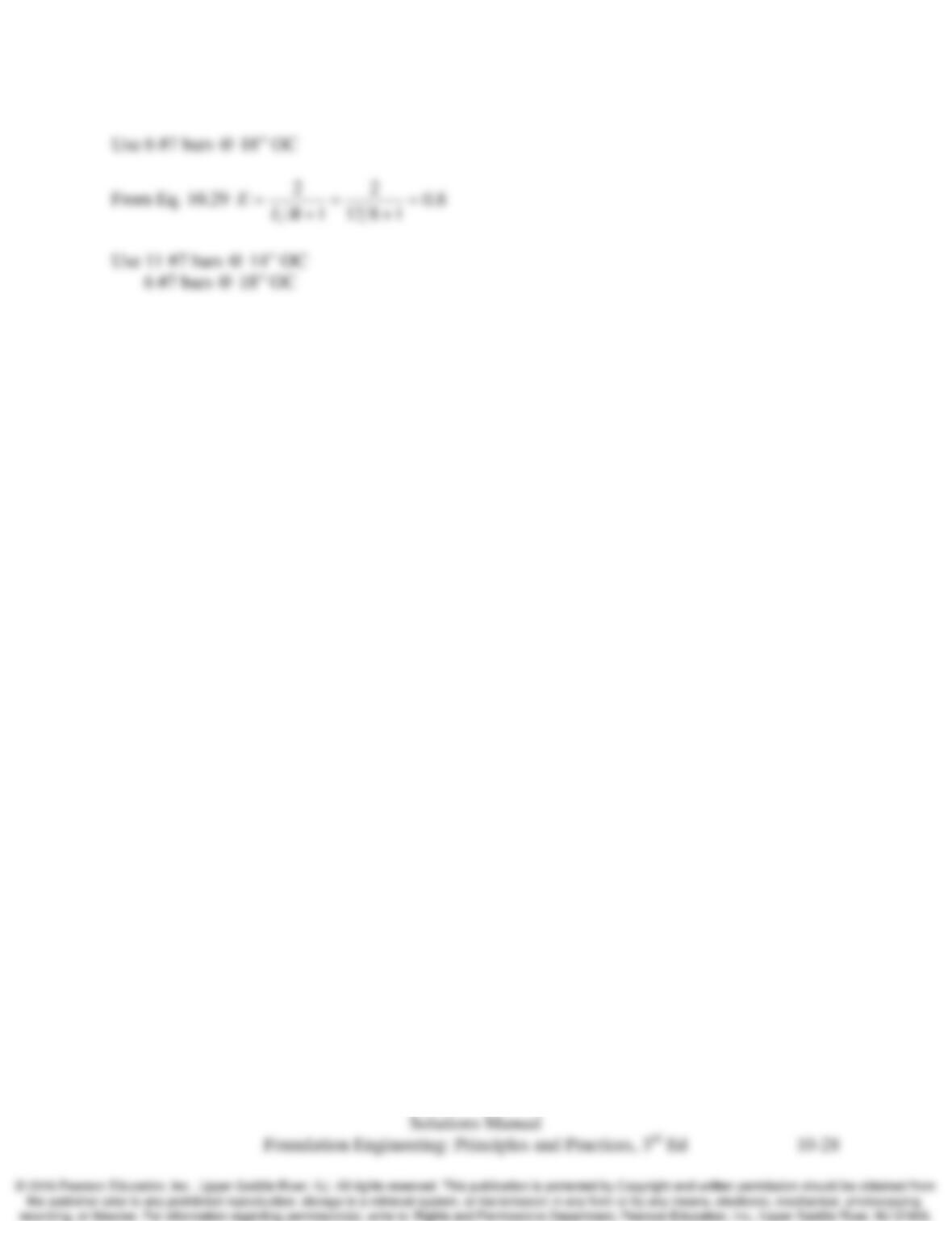
Use 11 #7 bars @ 14” OC
Short steel
Chap. 10 Spread Footings-Structural Design
Chap. 10 Spread Footings-Structural Design
10.15 Determine the required footing thickness and design the reinforcement for the combined footing
shown in Figure 10.30. Use concrete with fcʹ = 3,000 lb/in2 and reinforcing steel with fy = 60
k/in2.
Solution
Solution
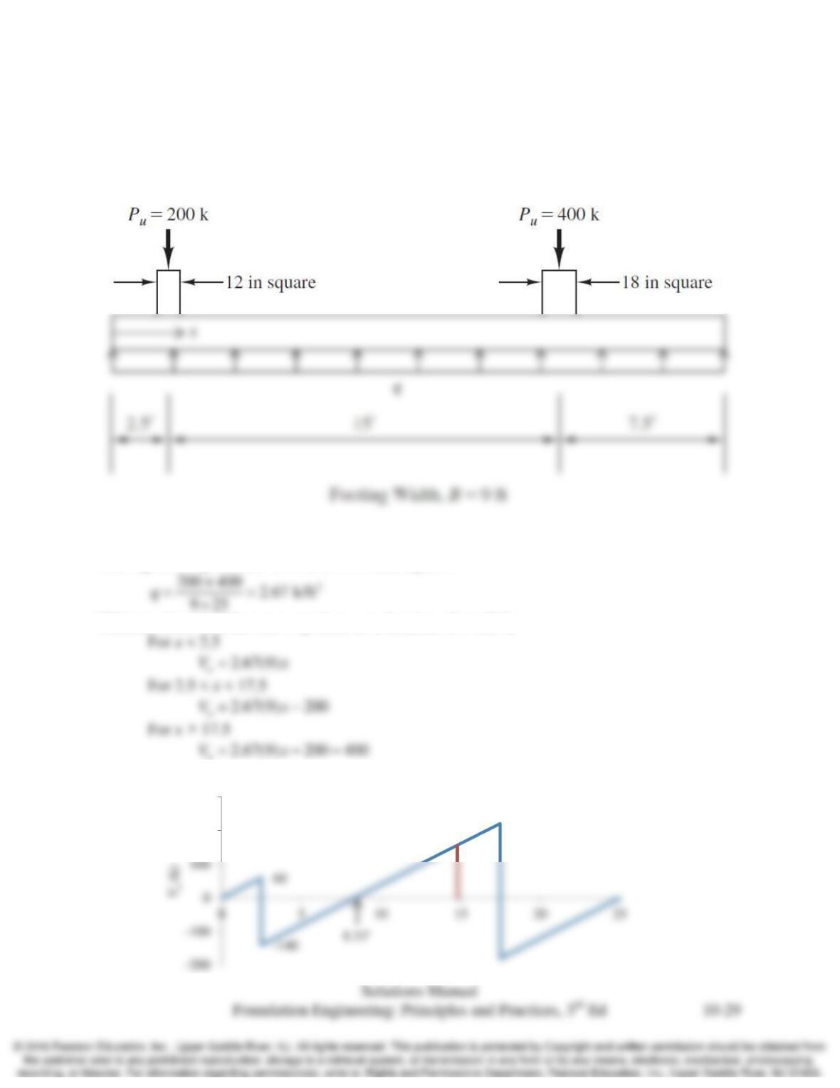
Bearing stress, q, on base will be uniform and equal to
Ultimate shear load for one–way shear as a function of x will be
Shear diagram is:
155 220
200
300
Chap. 10 Spread Footings-Structural Design
Design for shear
Critical section for 1-Way shear will be left of the right hand column at
0.75 275 206 k
nc
V
φ
Check 2–Way shear
( ) ( )
22
2.67 1.5 23.25 12 31.5 k
uc
V qc d=+= + =
( ) ( )( )
4 4(18 23.25) 23.25 3000
4 4 4( ) 854 k
1000
nc w c c
V bdf cddf +
′′
==+= =
( )
0.75 854 640 k
nc
V
φ
= =
> 31.5 OK
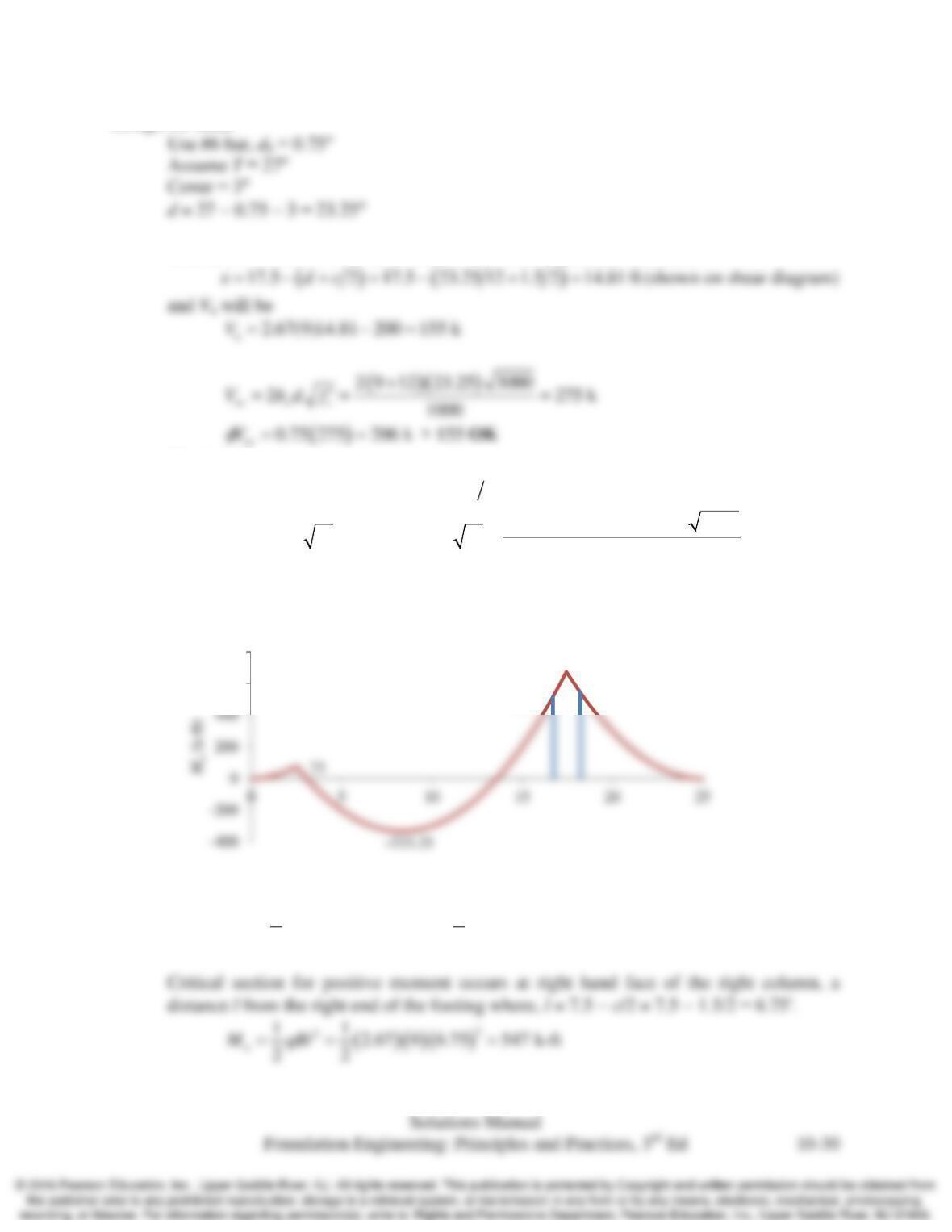
From the shear diagram the moment diagram is
Critical section for negative moment occurs at x = 8.33ʹ (where shear is zero)
( ) ( )( )( ) ( )
2
2
11
200 2.5 2.67 9 8.33 200 8.33 2.5 333 k-ft
22
u
M qBx x= + -= + -=–
517
620.75
547
600
800
Chap. 10 Spread Footings-Structural Design
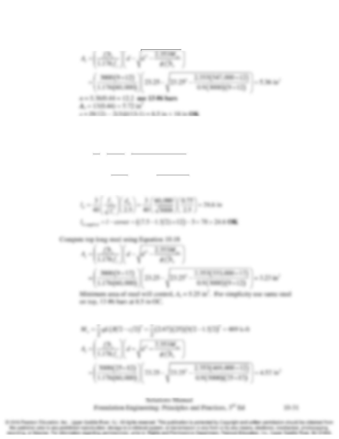
Compute bottom long steel using Equation 10.18
s = [9(12) – 2(3)]/(13-1) = 8.5 in < 18 in OK
Check minimum steel
( )( )
2
,min
0.0018 0.0018 9 12 27 5.25 in < 5.72
s
A BT= = ×= OK
Check ductility
( )
( )( )
22
11
5.72 60,000 1.47 in
0.85 3000 9 12
sy
n
c
Af
a
cfb
bb
= = = =
′×
23.25 1.47
0.003 0.003 0.044 0.005
1.47
n
t
n
dc
c
ε
—
= = = >
OK
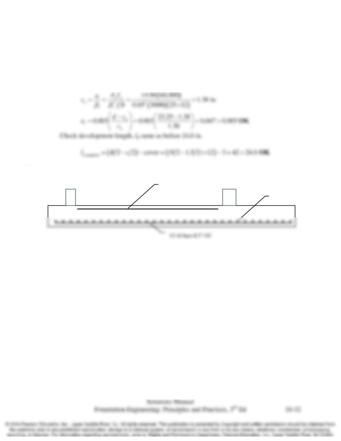
Check development length using Equation 10.23
Compute short steel using Equation 10.18
Chap. 10 Spread Footings-Structural Design
Minimum steel will control
( )( )
2
,min
0.0018 0.0018 25 12 27 14.58 in
s
A LT= = ×=
n = 14.58/0.44 = 33.1 use 34 #6 bars
As = 34(0.44) = 14.96 in2
s = [25(12) – 2(3)]/(34 – 1) = 8.9 in < 18 in OK
Check ductility
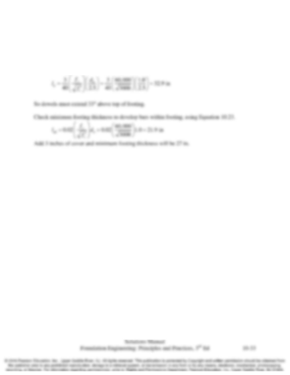
Final design
13 #6 bars 8.5ʺ OC
34 #6 bars 8.9ʺ OC
13 #6 bars 8.5ʺ OC
Chap. 10 Spread Footings-Structural Design
10.16 The column described in Problem 10.14 is reinforced with 6 #8 bars. Design the dowels required
to connect it with the footing, and show your design in a sketch.
Solution
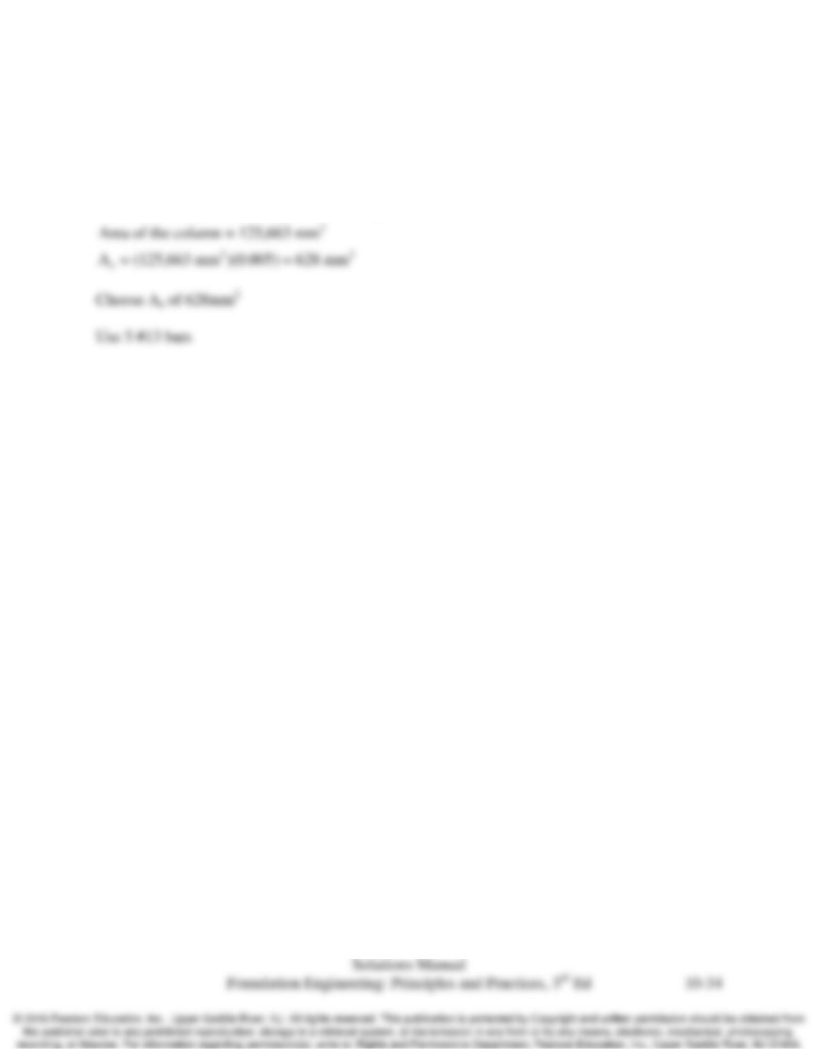
Check development length for # 8 bars to determine required length of dowels. Use Equation
10.23 assuming fy = 60,000 lb/in2 and fcʹ = 3,000 lb/in
Chap. 10 Spread Footings-Structural Design
10.17 A 400-mm diameter concrete column carrying a factored compressive load of 1500 kN is
supported on a spread footing. It is reinforced with eight metric #19 bars. Using
c
f′
= 18 MPa
and fy = 420 MPa, design the dowels for this connection.
Solution
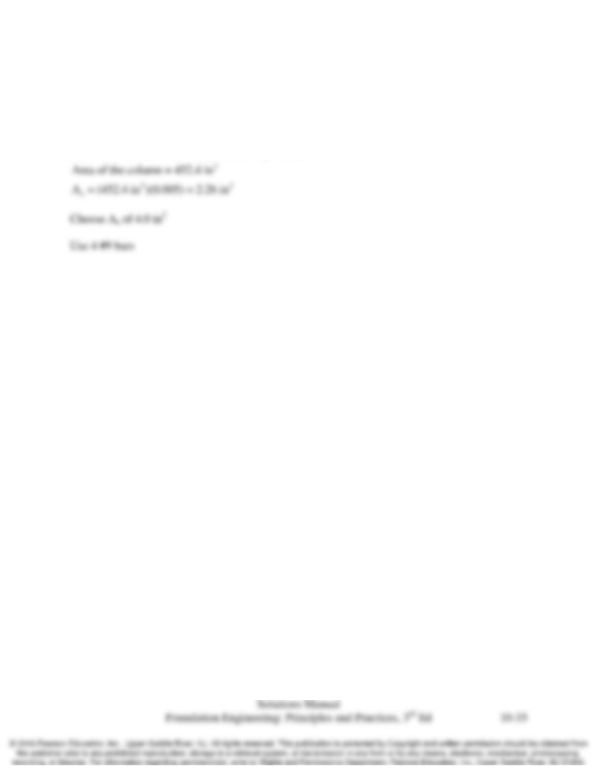
Use 4 dowels, metric #25, dia. =25.4mm,
2
101.6 mm
s
A=
Chap. 10 Spread Footings-Structural Design
10.18 A 24–inch square concrete column carries a factored compressive load of 900 k and a factored
shear load of 100 k. It is to be supported on a spread footing with
c
f′
= 3000 lb/ft2 and fy = 60
k/in2. Design the dowels for this connection.
Solution
Use 4 dowels, metric #25, dia. =1.0 in,
2
4.0 in
s
A=
Chap. 10 Spread Footings-Structural Design
10.19 A steel column with a square base plate is to be supported on a spread footing. The AISC
factored design loads are: Pu = 600 k compression and Vu = 105 k. Design an anchor bolt system
for this base plate and show your design in a sketch.
Solution
Assume a square base plate of 15 x15 in
Reduce the applied loads to a couple separated by 15 in:
Chap. 10 Spread Footings-Structural Design
10.20 A 400-mm square concrete column reinforced with eight metric #19 bars carries vertical dead
and live loads of 980 and 825 kN, respectively. It is to be supported on a 2.0 m × 3.5 m
rectangular footing. The concrete in the footing will have
c
f′
= 20 MPa and fy = 420 MPa. The
building will have a slab-on-grade floor, so the top of the footing must be at least 150 mm below
the finish floor elevation. Develop a complete structural design, including dowels, and show it in
a sketch.
Solution
Chap. 10 Spread Footings-Structural Design
10.21 A 12–in wide masonry wall carries dead and live loads of 6 k/ft and 9 k/ft, respectively and is
reinforced with #6 bars at 24 inches on center. The sustained load for settlement computation is
10.5 k/ft. This wall is to be supported on a continuous footing with
c
f′
= 2000 lb/in2 and fy=60
k/in2. The underlying soil has an allowable bearing pressure for bearing capacity of 5200 lb/ft2
(based on LRFD methods) and an allowable bearing pressure for settlement of 3000 lb/ft2.
Develop a complete structural design for this footing, including dowels, and show your design in
a sketch
Solution