CHAPTER 9 AUXILIARY VIEWS
PROBLEMS
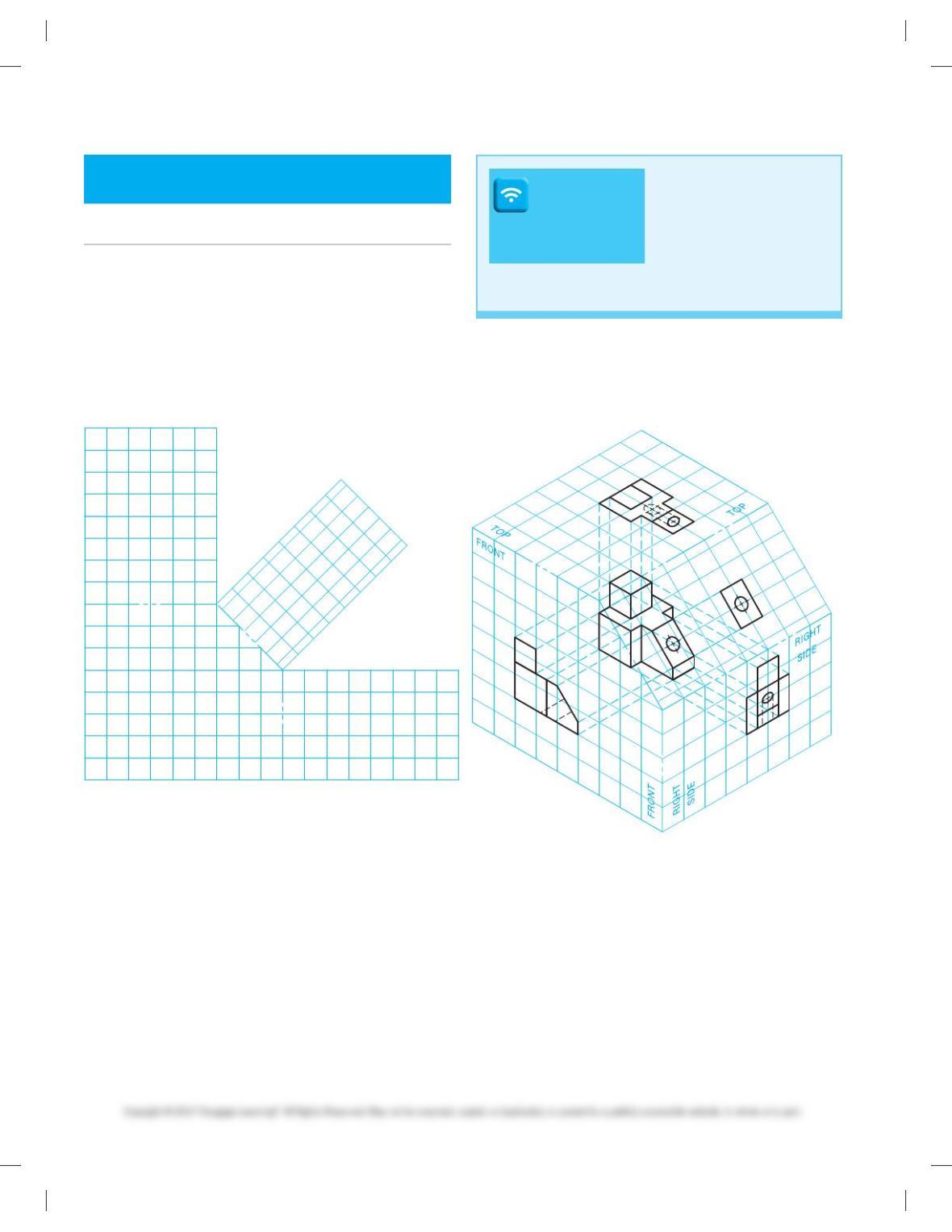
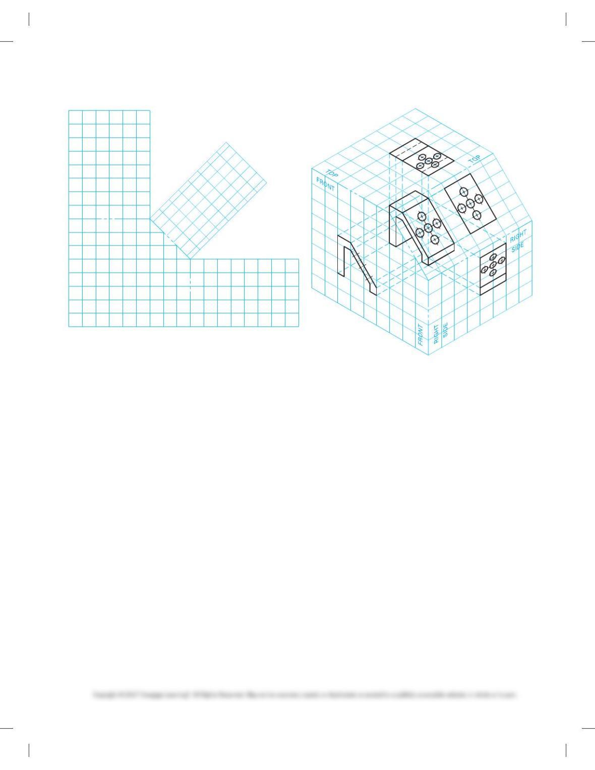
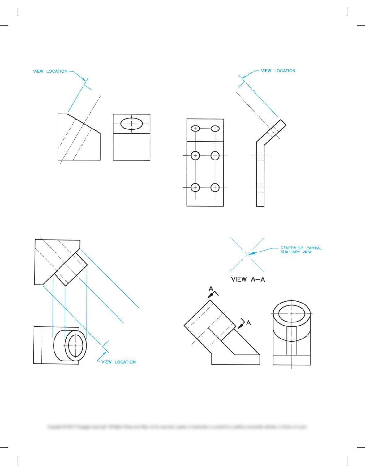
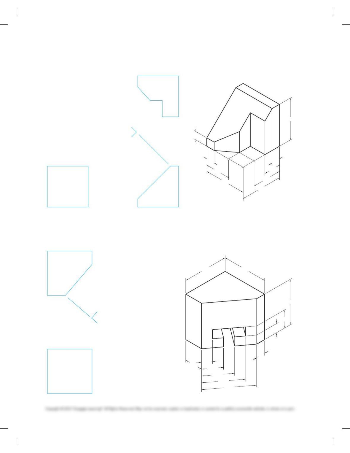
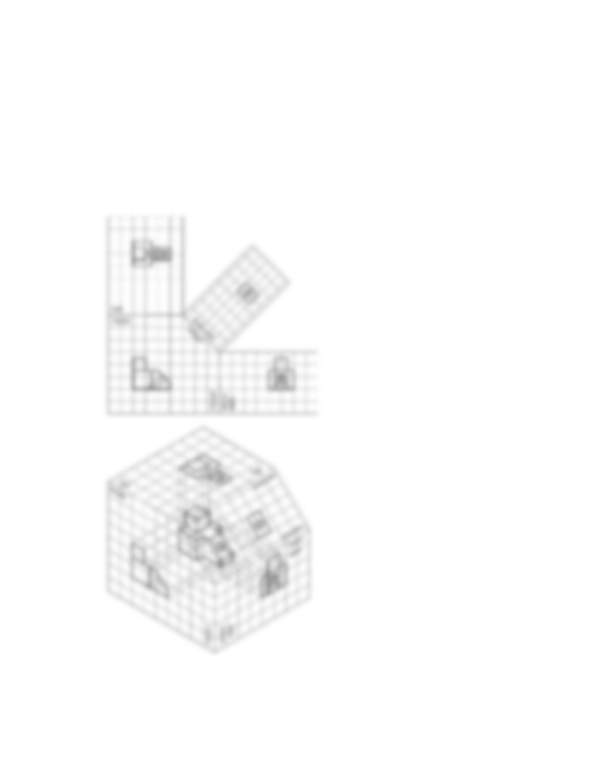
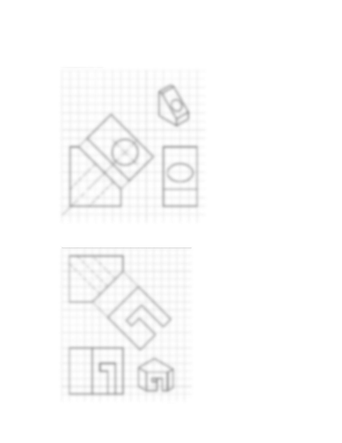
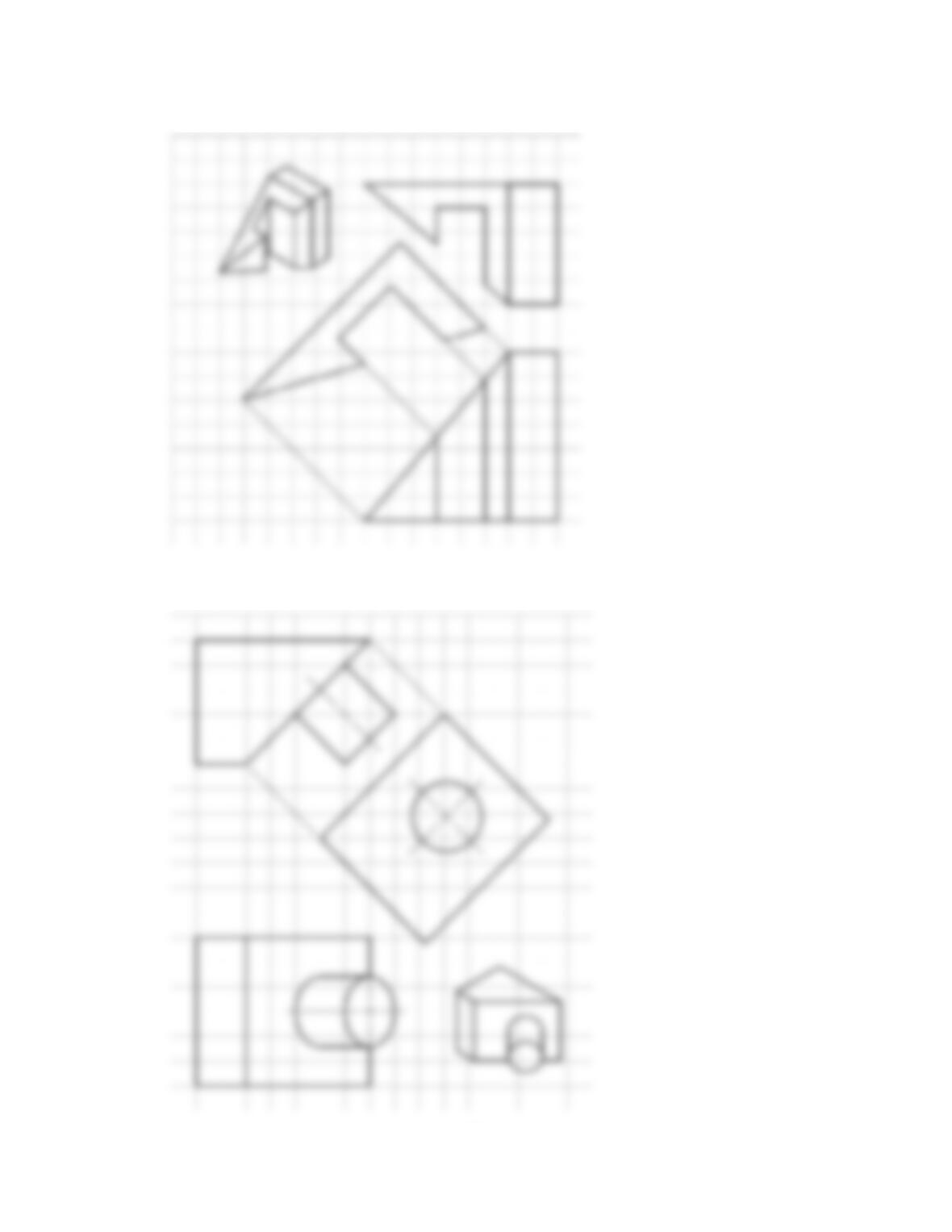
Part 1: Problems 9.1 and 9.2
Given each object displayed in a glass box with views projected
on to the glass box surfaces, draw the multiviews and auxiliary
view using third-angle projection. Each square on the given grid
represents 1 in. (25 mm). Use appropriate size ASME standard
sheet size and sheet blocks for each problem unless otherwise
specified by your instructor.
SIDE
FRONT
AUXILIARY
AUXILIARY
TOP
FRONT
RIGHT
FRONT
AUXILIARY
PROBLEM 9.1
DRAFTING
TEMPLATES
To access CADD template
files with predefined drafting
settings, go to the Student
Companion Website, select
Student Downloads and
Drafting Templates, and then
select the appropriate
template file.
59728_ch09_EOC_ptg01.indd 2 03/02/16 10:25 am
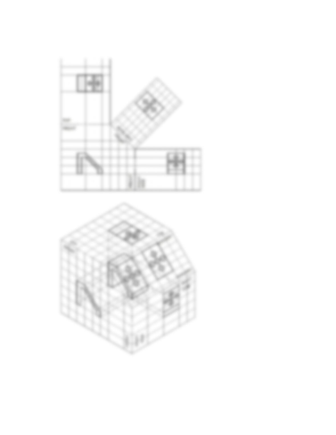
TOP
FRONT
SIDE
RIGHT
FRONT
AUXILIARY
FRONT
AUXILIARY
AUXILIARY
PROBLEM 9.2
59728_ch09_EOC_ptg01.indd 3 03/02/16 10:25 am
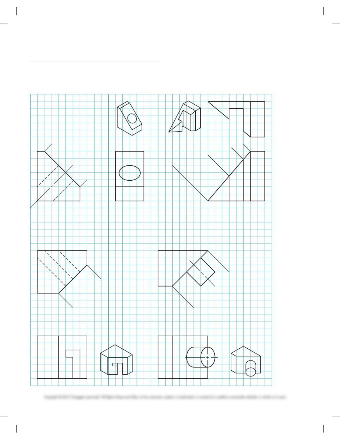
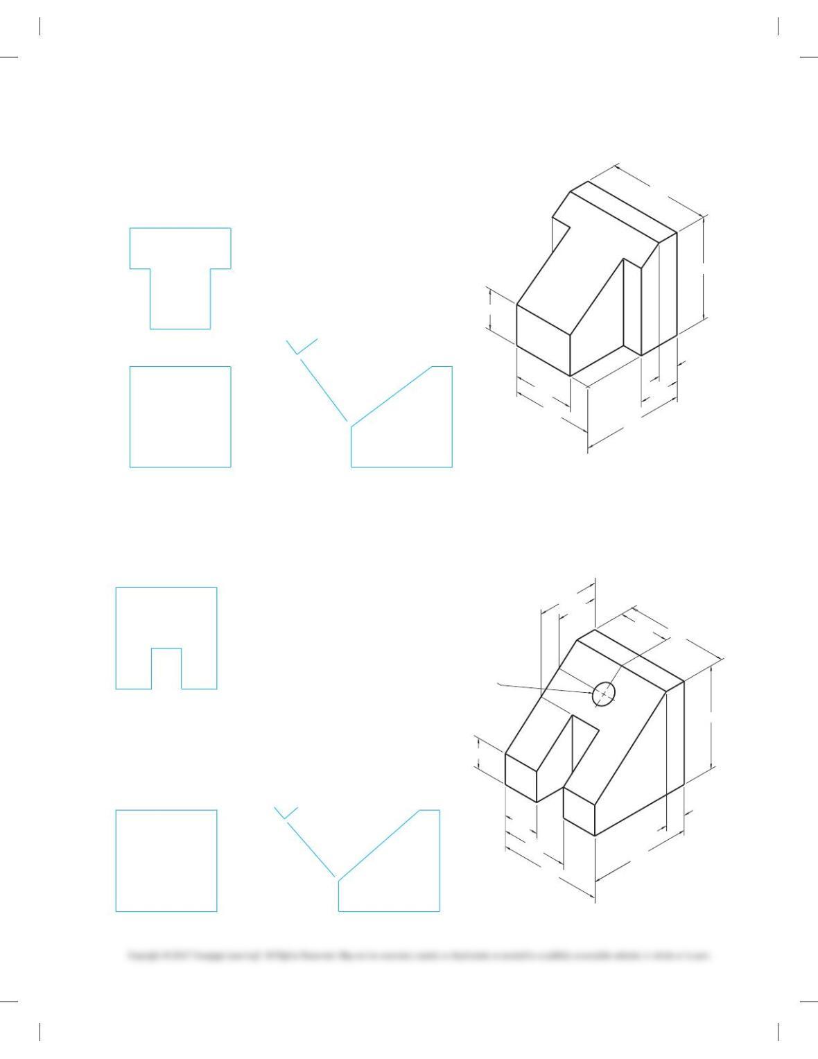
PROBLEM 9.3
PROBLEM 9.4
PROBLEM 9.5
PROBLEM 9.6
Part 2: Problems 9.3 through 9.6
Given objects with recommended multiviews and auxiliary view
having missing lines or mussing views, draw the multiviews and
auxiliary view using third-angle projection. Each square on the
given grid represents 1 in. (25 mm). Use appropriate size ASME
standard sheet size and sheet blocks for each problem unless
otherwise specified by your instructor.
59728_ch09_EOC_ptg01.indd 4 03/02/16 10:25 am
PROBLEM 9.7
PROBLEM 9.8
PROBLEM 9.9
PROBLEM 9.10
Part 3: Problems 9.7 through 9.14
Given objects with recommended multiviews and auxiliary view
having missing lines or missing views, draw the multiviews and
auxiliary view using third-angle projection. Make a print of each
page and use the copy to measure. Use appropriate size ASME
standard sheet size and sheet blocks for each problem unless
otherwise specified by your instructor.
59728_ch09_EOC_ptg01.indd 5 03/02/16 10:25 am
PROBLEM 9.11
PROBLEM 9.12
PROBLEM 9.13
PROBLEM 9.14
59728_ch09_EOC_ptg01.indd 6 03/02/16 10:25 am
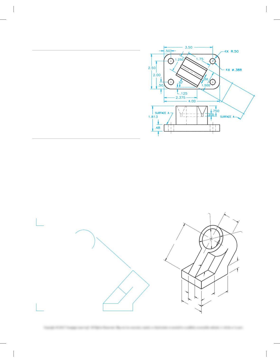
Part 4
PROBLEM 9.15 This problem provides you with dimen-
sioned pictorial views and a proposed start for your multiview
and auxiliary view layout. Draw the required multiviews and
auxiliary views. Use the given dimensions to create your final
drawing. Set up your drawings with a properly sized sheet, bor–
der, and sheet block. Properly complete the information in the
title block. Do not draw the pictorial view unless required by
your instructor. Do not draw the dimensions.
PROBLEM 9.15 Primary auxiliary view (in.)
Title: Angle V-block
Material: SAE 4320
Ø3.00
Ø2.25
4.50
1.00
4.00
2.00
48°
3.00
2.00
1.00
3.00
SUGGESTED VIEW LAYOUT
FRONT RIGHT SIDE
TOP
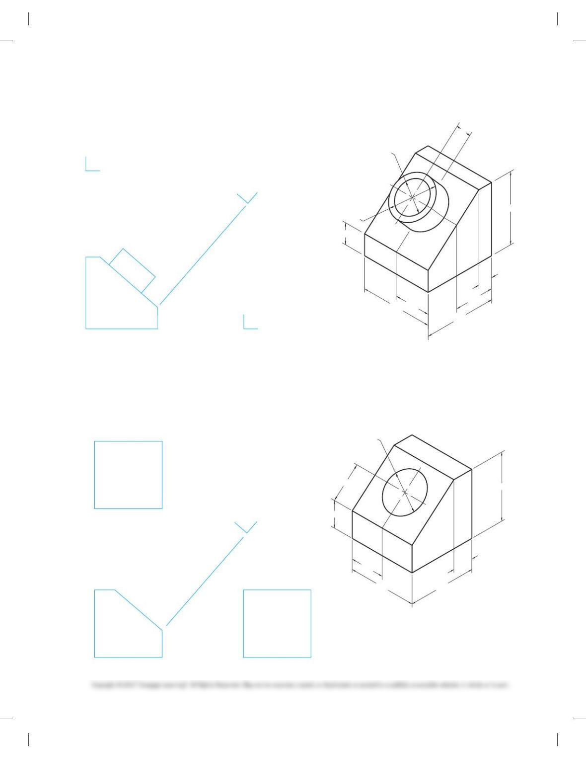
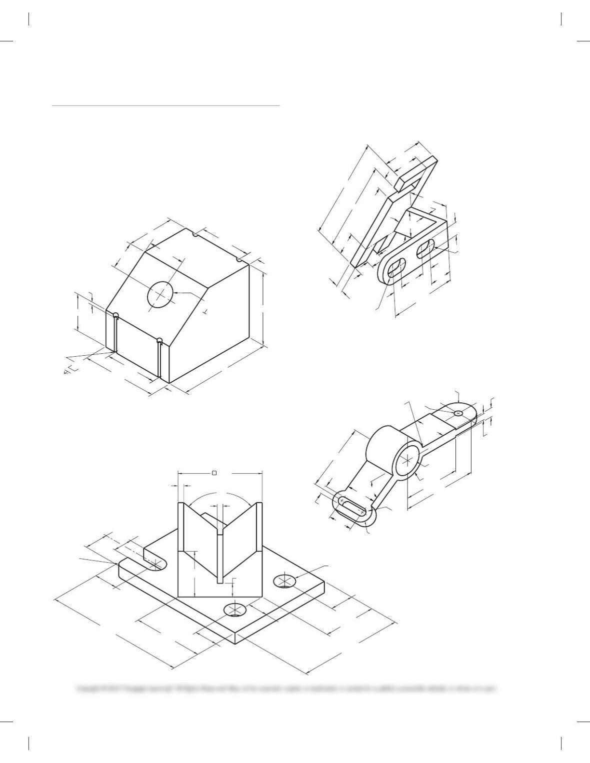
Part 5: Problems 9.16 Through 9.24
The following problems provide you with pictorial views that
contain dimensions and a recommended view layout. Draw the
multiviews and auxiliary view. The pictorial views are provided
to aid in visualization and to display the dimensions. You do not
need to draw the pictorial view. Use the given dimensions to cre-
ate your final drawing. Set up your drawings with a properly
sized sheet, border, and sheet block. Properly complete the infor-
mation in the title block. Do not draw the dimensions.
PROBLEM 9.16 Primary auxiliary view (in.)
Title: Cylinder Support
Material: Cast iron
59728_ch09_EOC_ptg01.indd 7 03/02/16 10:25 am
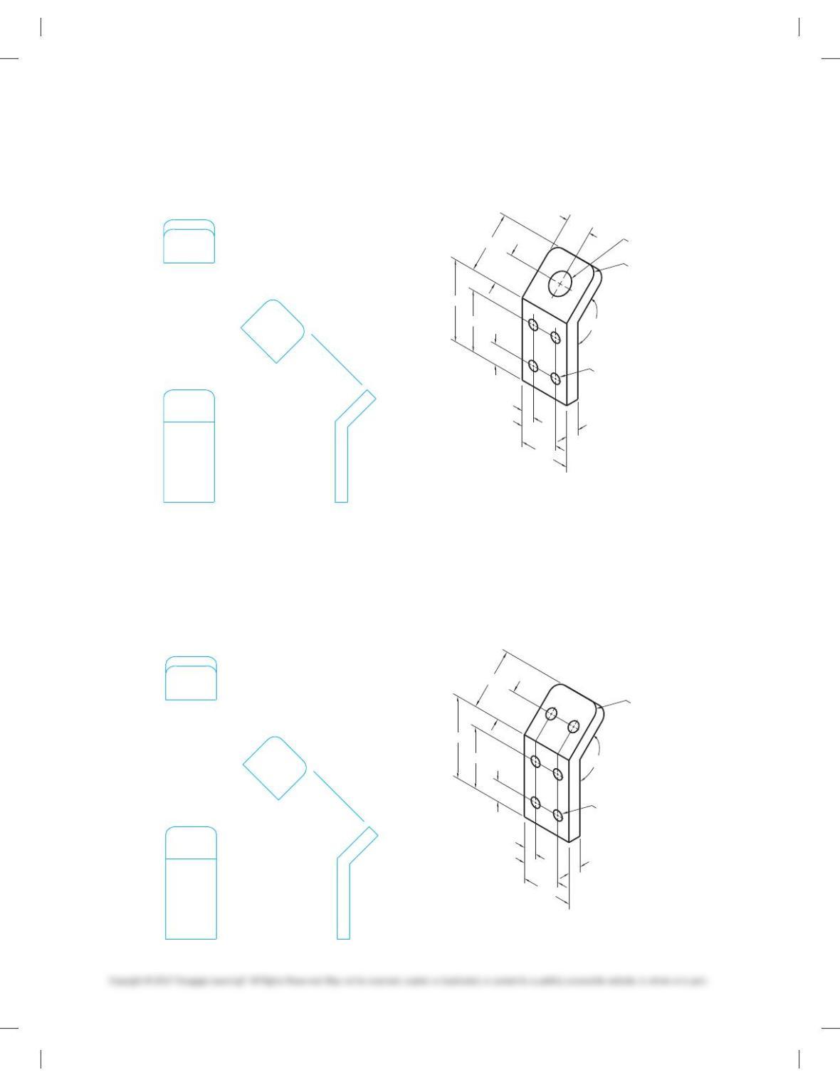
PROBLEM 9.18 Primary auxiliary view (in.)
Title: 135-1 Bracket
Material: Aluminum
PROBLEM 9.17 Primary auxiliary view (in.)
Title: 135 Bracket
Material: Aluminum
SUGGESTED VIEW LAYOUT
1.875
2.50
.625
.625
R.50
135°
4.00
2.50
1.25
1.00
3.00
4X Ø.50
Ø1.00
1.25
1.875
2.50
.625
.625
R.50
135°
4.00
2.50
1.25
1.00
3.00
6X Ø.50
SUGGESTED VIEW LAYOUT
59728_ch09_EOC_ptg01.indd 8 03/02/16 10:25 am
PROBLEM 9.19 Primary auxiliary view (in.)
Title: Support Base
Material: Cast aluminum
PROBLEM 9.20 Primary auxiliary view (in.)
Title: Shaft Support
Material: SAE 1020
1.50
Ø2.25
Ø3.00
1.50
5.00
2.50
5.00
2.75
1.00
5.00
SUGGESTED VIEW LAYOUT
TOP
RIGHT SIDE
AUXILIARY
2.50
2.00
5.00
2.50
5.00
1.50
5.00
Ø3.00
(PERPENDICULAR TO
SLANTED SURFACE)
SUGGESTED VIEW LAYOUT
59728_ch09_EOC_ptg01.indd 9 03/02/16 10:25 am
PROBLEM 9.21 Primary auxiliary view (in.)
Title: Spacer
Material: Cast iron
PROBLEM 9.22 Primary auxiliary view (in.)
Title: T–block
Material: SAE 4320
5.00
3.50
1.00
2.00
5.00
5.00
3.00
1.00
1.00
SUGGESTED VIEW LAYOUT
2.00
1.00
5.00
5.00
5.00
5.00
4.00
3.00
2.00
1.00
2.00
1.00
SUGGESTED VIEW LAYOUT
59728_ch09_EOC_ptg01.indd 10 03/02/16 10:25 am
PROBLEM 9.23 Primary auxiliary view (in.)
Title: T-wedge
Material: Mild steel
PROBLEM 9.24 Primary auxiliary view (in.)
Title: Brace
Material: Cast iron
1.00
5.00
5.00
3.25
1.75
1.50
5.00
5.00
3.00
2.00
Ø1.00
(PERPENDICULAR TO
SLANTED SURFACE)
2.50
SUGGESTED VIEW LAYOUT
5.00
5.00
1.00
5.00
2.00
4.00
3.00
2.00
SUGGESTED VIEW LAYOUT
59728_ch09_EOC_ptg01.indd 11 03/02/16 10:25 am
Part 6: Problems 9.25 Through 9.37
Problems 9.25 through 9.37 provide dimensioned pictorial views.
Use the given information to select and draw the necessary mul-
tiviews and auxiliary view or views. Do not draw the pictorial
view. Set up your drawings with a properly sized sheet, border,
and sheet block. Properly complete the information in the title
block. Do not draw the dimensions.
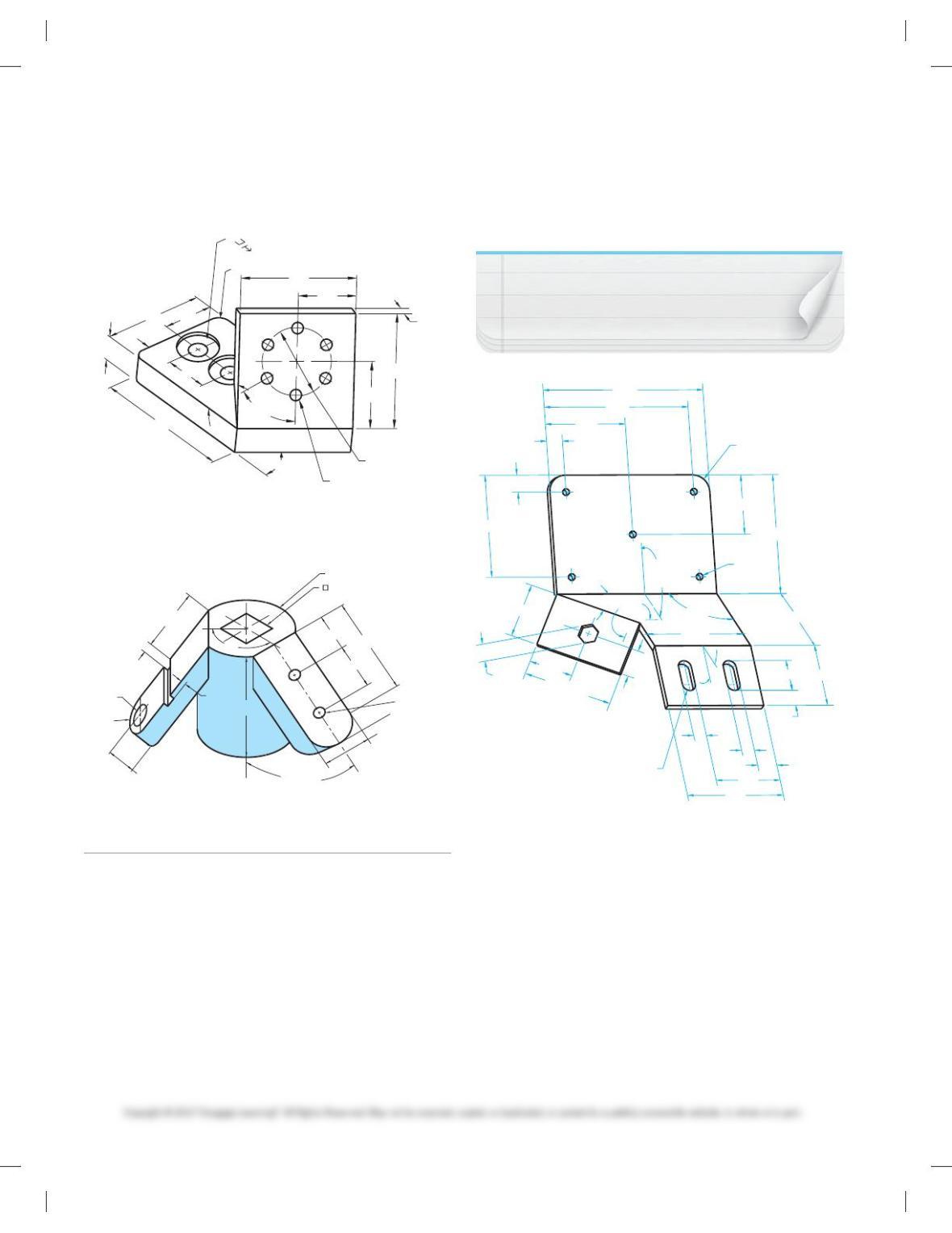
PROBLEM 9.25 Primary auxilary view (in.)
Part Name: Angle Base
Material: Mild steel
Ø1.031 THRU
( TO SLANTED
SURFACE)
4 X Ø.125
Ø.250
.125
1.063
3.26
.50
2.26
3.26
2.125
(.125)
2.26 .50
1.66
1.63
4.125
R12.5 (FULL RADIUS)
4X R
608
25
25
14
42
63.5
17
12
38
117.5
104
10
6
14
10
14
28
6
PROBLEM 9.27 Primary auxiliary view (in.)
Title: Angle V-block
Material: Mild steel
Base: .50 thick
3.00
2X .25
908
.25
2X Ø.80
.625
2.00
2X 1.00
2X .80
2X 1.00
2.25
4.50
2X 1.00
2X 1.00
3.00
6.00
.875
2X R.30
PROBLEM 9.26 Primary auxiliary view (metric)
Part Name: Belt Guide
Material: Aluminum
PROBLEM 9.28 Primary auxiliary view (metric)
Part Name: Pivot Link
Material: Aluminum number 195
R (FULL R)
Ø15
Ø57
R19
2X R
(FULL RADIUS)
Ø76
4X R6
15
121
156
50
64
19
12.7
63.5
117.9
358
59728_ch09_EOC_ptg01.indd 12 03/02/16 10:25 am
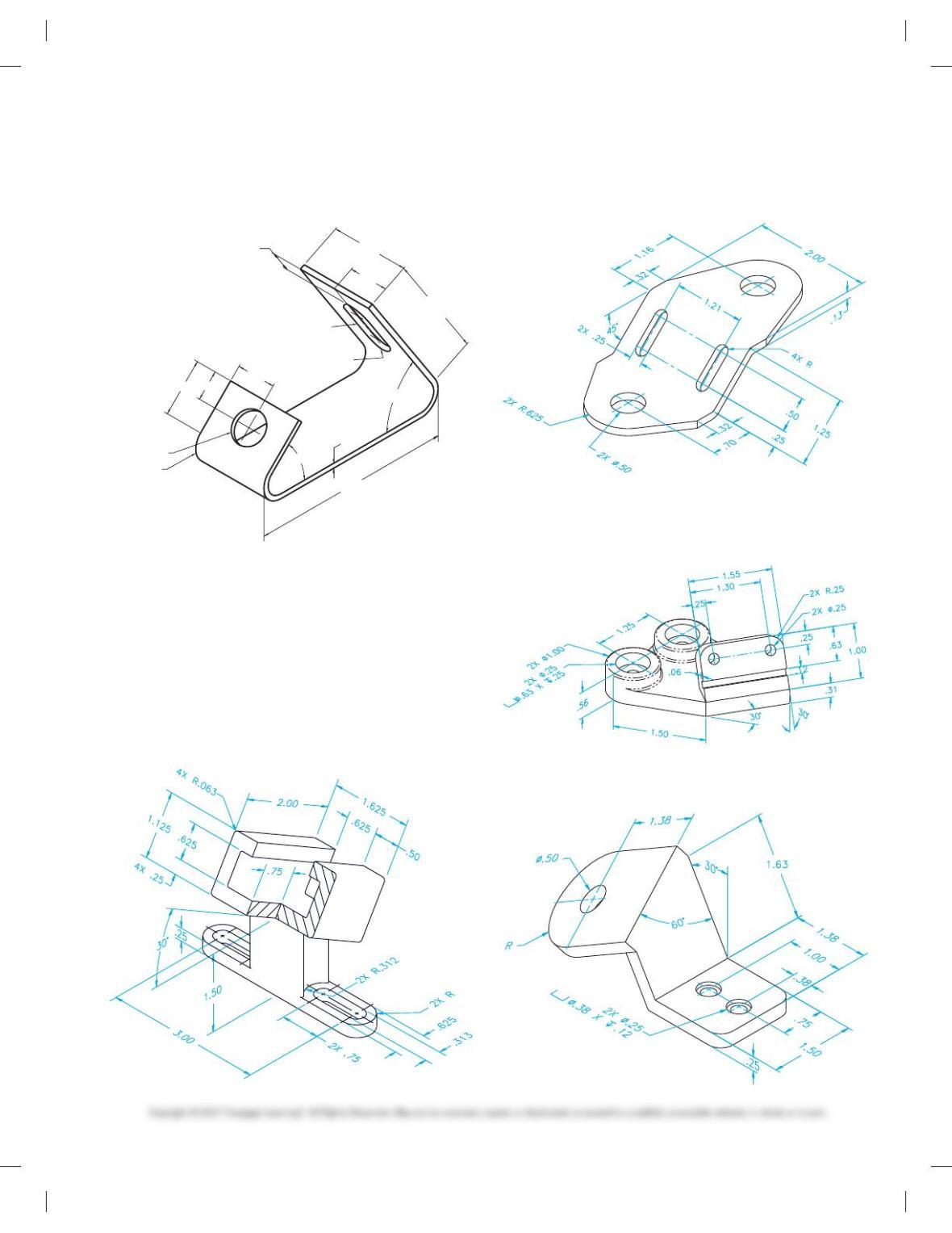
PROBLEM 9.29 Primary auxiliary view (in.)
Part Name: Mounting Bracket
Material: Mild steel
2.00
3.125
1.00
.375
.75 X 2.25
2X R
608
.125
45
8
6.00
1.75
.875
Ø.750
2X R.500
1.00
PROBLEM 9.30 Design change
Use Problem 9.29 to change the 6.00 length to 3.25.
PROBLEM 9.31 Primary auxiliary view (in.)
Part Name: Adjustable Slide Bracket
Material: 6061-T6 Aluminum
Fillets and Rounds: R.031 unless otherwise specified.
PROBLEM 9.32 Primary auxiliary view (in.)
Part Name: Offset Bracket
Material: Mild steel
Minumun Inside Bend: R.06
PROBLEM 9.33 Secondary auxiliary view (in.)
Part Name: Angle Bracket
Material: 6061-T6 Aluminum
Fillets and Rounds: R.031 unless otherwise specified.
PROBLEM 9.34 Secondary auxiliary view (in.)
Part Name: Slide Rail Support
Material: SAE 1040
Rounds: R.25
59728_ch09_EOC_ptg01.indd 13 03/02/16 10:25 am
NOTE: Confirm dimensions during creation and
make revisions as needed. Verify changes with
your instructor.
PROBLEM 9.35 Secondary auxiliary view (metric)
Part Name: Skewed Face Plate
Material: SAE 1040
3
6X Ø6 THRU
15
Ø35
Ø10
R6
25
55
8
6X 608
358
80
30
60
16
15
60
30
60
35
Ø22
PROBLEM 9.36 Secondary auxiliary view (in.)
Part Name: Angle Bracket
Material: Cast iron
1358
2X 458
2X .500
2X 1.25
2X R
1.125
.750
.125
.063
2X .375
.375 THRU
Ø1.00
.438
.375
Ø.375 2X Ø.125
PROBLEM 9.37 Primary and secondary auxiliary views
(metric)
Part Name: Chassis Switch Plate
Material: 4-mm-thick .416 Stainless steel
408
240
8
225
250
125
25
25
150
80
HEX 26
65.3
40
150
20
4X R
20
100
30
25
100
50
150
5X Ø10
175
87.5
CONFRM
2X R25
1308
908
(150)
30
8
Part 7: Problems 9.38 and 9.39
The following problems provide pictorial views that contain
dimensions and a recommended view layout. Draw the re-
quired multiviews and auxiliary view or views. The pictorial
views are provided to aid in visualization and to display the
dimensions. You do not need to draw the pictorial view. Use the
given dimensions to create your final drawing. Set up your
drawings with a properly sized sheet, border, and sheet block.
Properly complete the information in the title block. Do not
draw the dimensions.
59728_ch09_EOC_ptg01.indd 14 03/02/16 10:25 am
6.750
1.000
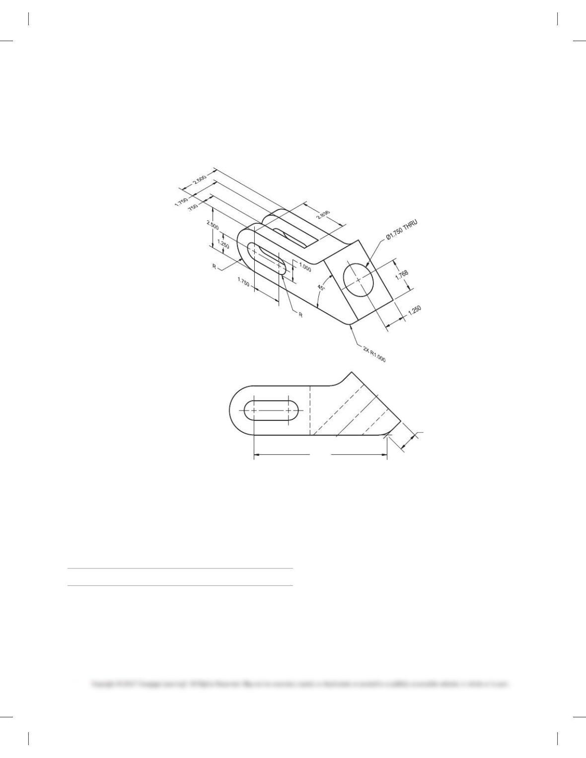
PROBLEM 9.39 Rotated primary auxiliary view (in.)
Title: Coupler
Material: Cast iron
Given the same part provided in Problem 9.38, draw the required
multiview or views and auxiliary view or views using the arrow
and rotation arrow method.
MATH PROBLEMS
Part 8: Problems 9.40 Through 9.49
A solar panel is in the shape of a 49 3 89 rectangle. With the sun
overhead, what is the area of the shadow it casts on the ground if
it is inclined at the following angles?
PROBLEM 9.40 108
PROBLEM 9.41 208
PROBLEM 9.42 308
PROBLEM 9.43 808
PROBLEM 9.44 908
PROBLEM 9.45 What should be the area of a solar panel
inclined at 458 if the projected area from an overhead sun is to
be 100 ft2?
PROBLEM 9.46 A circular sign with an area of 77.8 ft2 casts a
shadow on the ground. The area of the shadow is 26.6 ft2. If the
sun is overhead, what is the angle that the sign is inclined from
the ground?
PROBLEM 9.47 A long post is sticking up from the ground at
an angle of 358. The sun is overhead and casting a shadow 98.3
feet long onto the ground. How long is the post?
PROBLEM 9.48 A square sign measuring 3 meters on an edge
is inclined at an angle of 258 to the ground. What is its projected
area onto the ground?
PROBLEM 9.49 A solar panel in the shape of a 49 3 89 rect–
angle casts a shadow with an area of 16 ft2 when the sun is over-
head. To what angle is it inclined?
PROBLEM 9.38 Rotated primary auxiliary view (in.)
Title: Coupler
Material: Cast iron
Draw the required multiview or views and auxiliary view or views
using the viewing-plane line rotation method.
59728_ch09_EOC_ptg01.indd 15 03/02/16 10:25 am
80
Chapter 9
Auxiliary Views
Solutions to End-of- Chapter Problems
Part 1: Problems 9.1 and 9.2
PROBLEM 9.1
81
PROBLEM 9.2
82
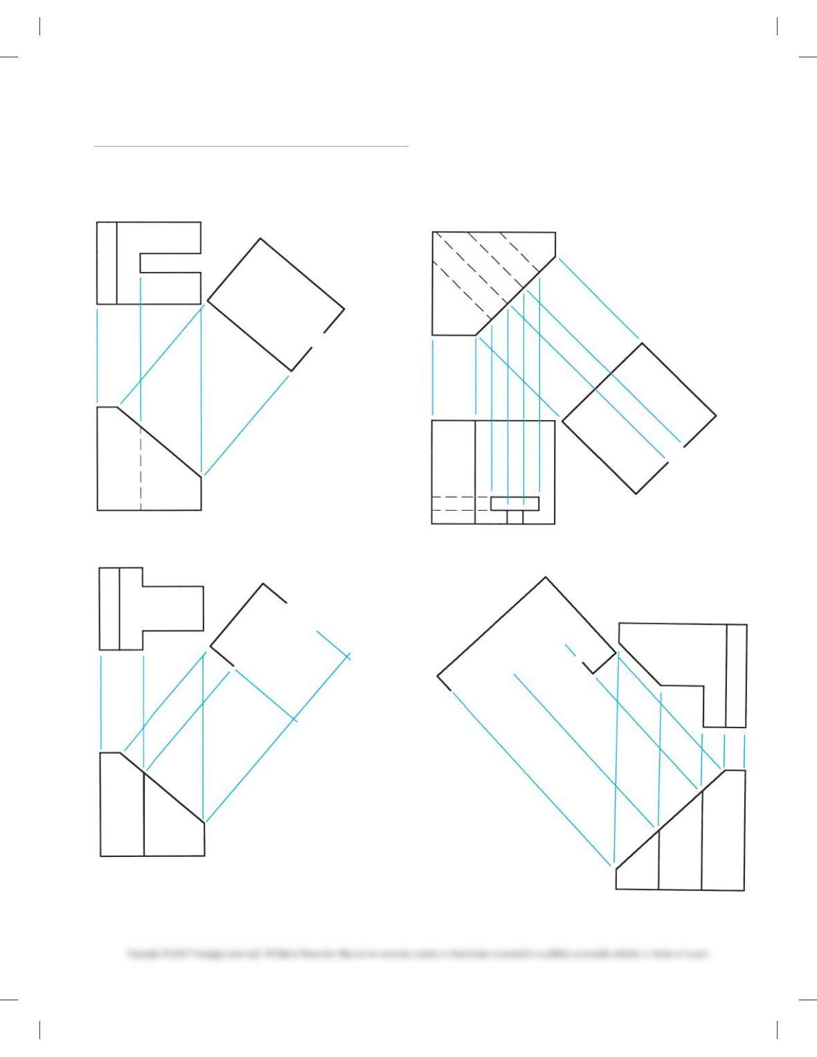
Part 2: Problems 9.3 Through 9.6
PROBLEM 9.3
PROBLEM 9.4
83
PROBLEM 9.5
PROBLEM 9.6