CHAPTER 24 CIVIL DRAFTING
PROBLEMS
INSTRUCTIONS
Determine the sheet size based on the drawing requirements.
Use a border and architectural-style title block as described in
Chapter 22, Structural Drafting. Metric scales can be substituted
if preferred by your supervisor or instructor. Include a north ar-
row and note the scale where applicable.
Part 1: Problems 24.1 Through 24.11
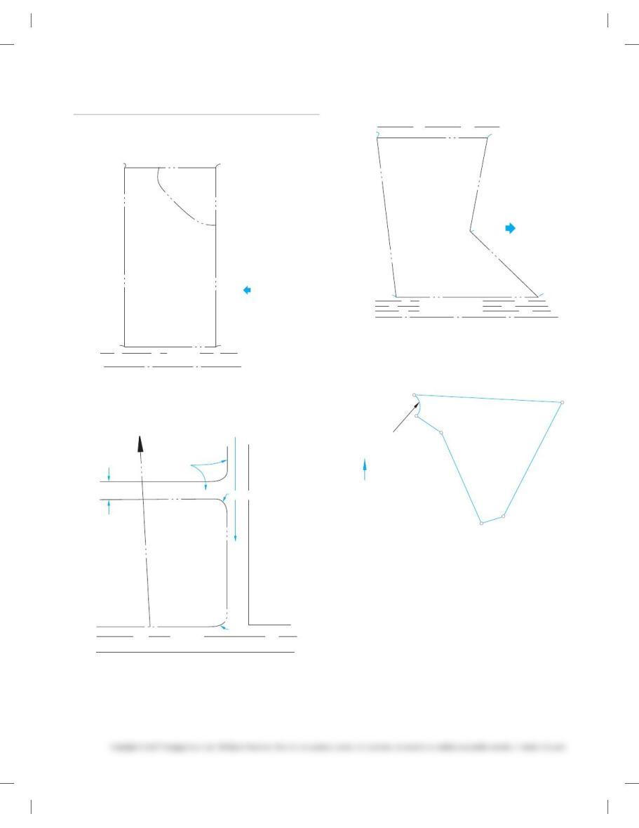
PROBLEM 24.1 Draw an open traverse at a scale of 10 5 209
using the following information:
From POB, traverse 34.239 at S 618429 E,
then 15.699 at S 44879 E,
then 40.899 at N 788489 E,
then 39.339 at N 568149 E.
Be sure to label each course.
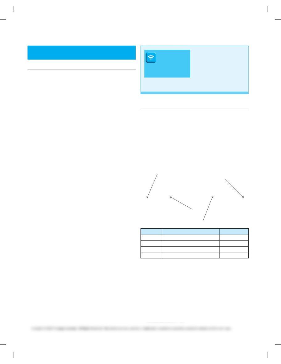
PROBLEM 24.2 Give the azimuth angles as well as the bear-
ings of the lines shown. Fill in the values in the following table.
POB POB
POB POB
Line Azimuthal Angle Bearing
AB
CD
EF
GH
PROBLEM 24.3 Draw a traverse at a scale of 10 5 209 using
the following lengths and bearings. What kind of traverse is
this?
21 feet at N 40879 E,
77 feet at S 84899 E,
19 feet at S 258299 E,
48 feet at S 398229 W,
31 feet at S 76899 W,
65 feet at N 348579 W.
DRAFTING
TEMPLATES
To access CADD template
files with predefined drafting
settings, go to the Student
Companion Website, select
Student Downloads and
Drafting Templates, and then
select the appropriate
template file.
59728_ch24_EOC_ptg01.indd 2 03/02/16 10:38 am

PROBLEM 24.4 Transfer the information shown on the fol-
lowing figure. Then draw a traverse at a scale of 10 5 209 using
the following lengths and azimuth angles. What kind of tra-
verse is this?
23 feet at an angle of 1318409,
11 feet at an angle of 231889,
36 feet at an angle of 1138259,
49 feet at an angle of 648399,
27 feet at an angle of 3038509,
36 feet at an angle of 658339.
POB
KNOWN
POINT
PROBLEM 24.5 Transfer the information shown on the fig-
ure below. Then draw a deflection angle traverse at a scale of
10 5 409 using the following lengths and bearings. Be sure to
use proper notation for the deflections. What type of traverse
is this?
489 at S 638469 E,
339 at S 378329 E,
719 at N 868109 E,
239 at S 81849 E,
739 at S 73899 E.
POB
BENCH
MARK
PROBLEM 24.6 Complete the leveling notes that were gath-
ered by the survey crew. Create a leveling notes table and fill in
the HI and elevations for each station.
STA.
0+00
STA.
2+11 STA.
3+71
STA.
5+40
STA.
6+58
ROD READING:
8.79
ROD
READING:
9.66
ROD
READING:
13.92
ROD
READING:
5.78
ROD
READING:
7.21
ROD
READING:
3.12
ROD
READING:
11.56
ROD READING:
12.20
HI=
HI=
HI=
HI=
TP4
TP3
TP2
TP1
ELEV.=
ELEV.=
ELEV.=
ELEV.=
POB
BM 124
ELEV. 27.88
59728_ch24_EOC_ptg01.indd 3 03/02/16 10:38 am
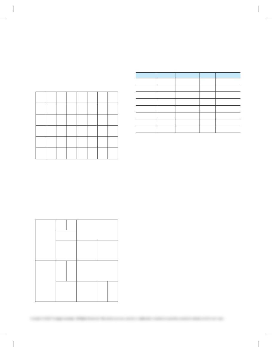
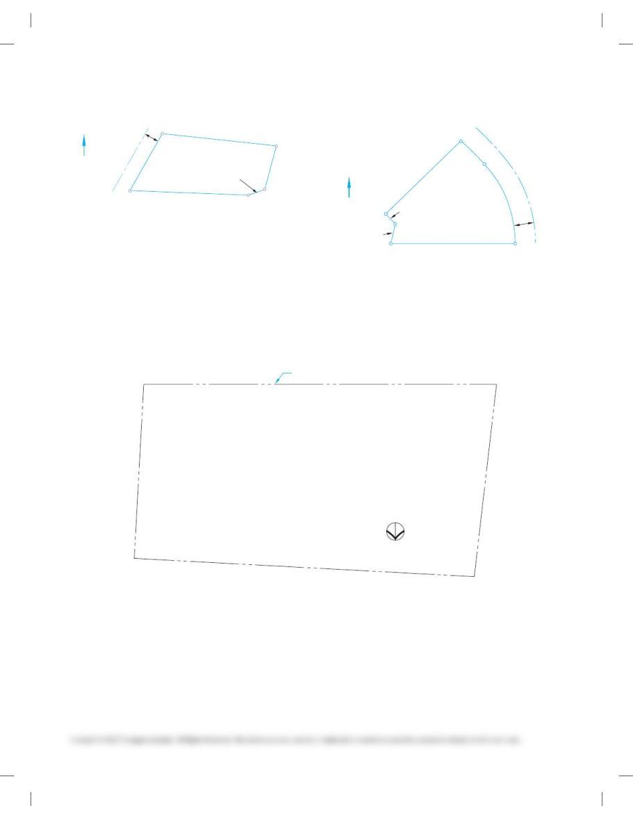
PROBLEM 24.7 Draw the grid and mark the following
townships as shown:
A. Township: T2S, R2W
B. Township: T3N, R4E
C. Township: T1N, R2E
D. Township: T2S, R2E
E. Township: TIN, R4W
NORTH
BASELINE EAST
PRINCIPAL MERIDIAN
WEST
SOUTH
PROBLEM 24.8 Draw the section grid and mark the follow-
ing parcels of land as shown:
A. Parcel: SW 1/4, SE 1/4
B. Parcel: W 1/2, NW 1/4
C. Parcel: W 1/2, NE 1/4, SW 1/4
D. Parcel: NE 1/4, NE 1/4, NW 1/4
E. Parcel: E 1/2, SE 1/4, SE 1/4
EASTWEST
NORTH
SOUTH
PROBLEM 24.9 Complete the leveling notes that were gath-
ered by the survey crew. Then plot the resulting profile using
10 5 109 for the vertical scale and 10 5 409 for the horizontal
scale.
Printed by Permission of the City of Portland
BM 12 17.31 7.46 34.12
0 130 6.83 4.87
0 155 9.66 7.72
1 105 14.30 10.13
1 145 12.20 13.29
1 185 7.12 15.82
2 115 10.04 12.73
2 140 BM 13
ElevationF.S. (–)H.I.B.S. (+)Station
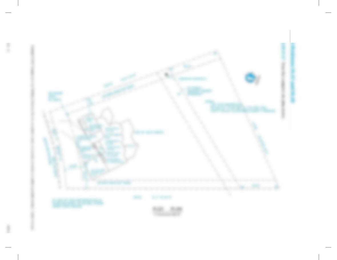
PROBLEM 24.10 Answer the following question using the
drawing on the following page.
What is the vertical scale?
What is the horizontal scale?
What is the degree of curve of the sewer?
Where is the property located in relation to the public-land
survey?
If the IE at MH-4 is 309.75 and the IE at MH-5 is 313.50, then
what is the grade slope?
What is the contour interval?
59728_ch24_EOC_ptg01.indd 4 03/02/16 10:38 am
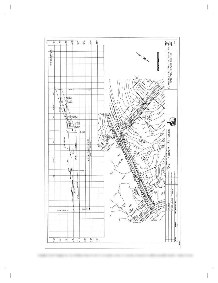
SEWER CURVE DATA
D = 1452’41.68″
R = 459.68′
L = 119.37′
PLAN
SCALE
50
SCALE FEET
02550 100
59728_ch24_EOC_ptg01.indd 5 03/02/16 10:38 am
PROBLEM 24.11 Complete the unknown values that were
given at the beginning of the chapter (see Figure24.2, textbook
page 899).
Part 2: Problems 24.12 Through 24.19
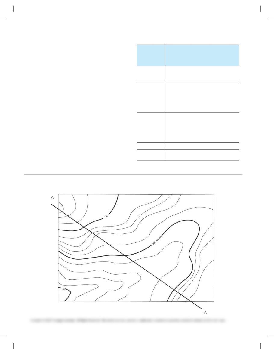
PROBLEM 24.12 Draw a profile from this contour, drawing along line A-A. Use a vertical scaleof 10 5 109. Make your drawing
proportional to the given drawing.
Station
Transit Line for Valerian Lane
From Erika Street (Bearing
N 56°16′ W) to Quincey Avenue
(Bearing N 31°25′ W)
0 100 255.78′ N 67°37′ W from BM 151
Begin Project to centerline of Erika Street.
Then 132.00′ S 33°44′ W to P.C.
STA 1 132 P.C. to the left
Curve Data
R = 200′
D= 47°23′
L = ––––
D = ––––
STA ____ P.R.C.
Curve Data
R= 170′
D= 72°15′
L = ––––
D = ––––
STA ____ P.T.
STA ____ S58°36’W from STA _____ to
End Project centerline of Quincey Avenue
59728_ch24_EOC_ptg01.indd 6 03/02/16 10:38 am
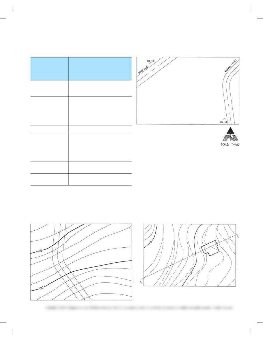
PROBLEM 24.13 Draw a roadway, Jean Road, from the following table. Be sure to include scale (10 5 1009) and north arrow.
Make your drawing proportional to the given drawing.
Station
Transit Line for Jean Road
From Rory Blvd (Bearing
N 538149 E) to Murphy Court
(Bearing N 88159 W)
0 1 00
Begin Project
93.249 S 278429 W from BM
43 to centerline of Rory Blvd. Then
147.939 S 808159 E to P.C.
STA ____ P.C. to the right
Curve Data
R 5 1159
D 5 47.008
L 5 ––––
D 5 ––––
STA ____ P.T., then 50.009 S 338159 E
STA ____ P.C. to the left
Curve Data
R 5 1029
D 5 65.008
L 5 ––––
D 5 ––––
STA ____ P.T., then 149.569 N 818459 E to
centerline of Murphy Court
STA ____
End Project
Length and bearing from
BM 44:____
PROBLEM 24.14 A proposed highway is shown. Using an
angle of repose of 1:1-1/2 and a contour interval of 109, and as-
suming the proposed highway will be level with an elevation of
120 feet, draw the proposed cut and fill areas. Use different
symbols for the cut and fill. Make your drawing proportional
to the given drawing.
PROBLEM 24.15 The building site needs some contour
changes to accommodate the new house being built. Draw a
profile line along line A-A, showing the cut and fill needed.
Draw the profile at 10 5 409 horizontal and 10 5 109 vertical.
Make your drawing proportional to the given drawing.
59728_ch24_EOC_ptg01.indd 7 03/02/16 10:38 am
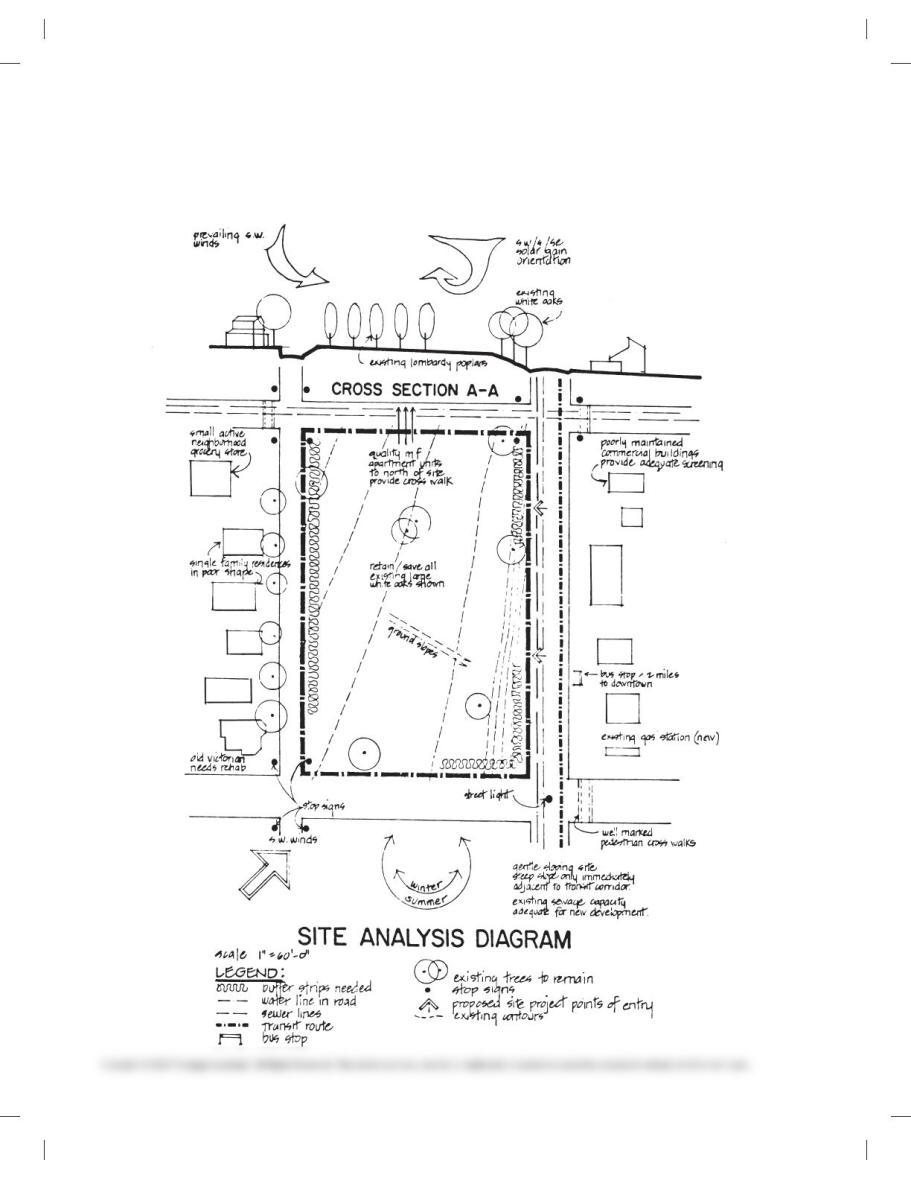
PROBLEM 24.16 Site analysis plan
Use a scale of 10 5 609 to take measurements from the engineering layout shown below. Convert the measurements to a drawing on
C-size sheet using a scale of 10 5 209. Make a 100% print of the problem page and use the hard copy to establish dimensions.
Courtesy Planning Department, Clackamas County, Oregon.
59728_ch24_EOC_ptg01.indd 8 03/02/16 10:38 am
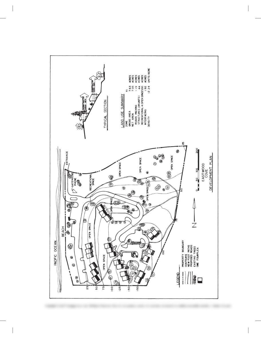
PROBLEM 24.17 Planning unit development
Use the graphic scale shown in the layout below to take measurements. Convert to a scale of 10 5 509 on an appropriately sized sheet.
59728_ch24_EOC_ptg01.indd 9 03/02/16 10:38 am
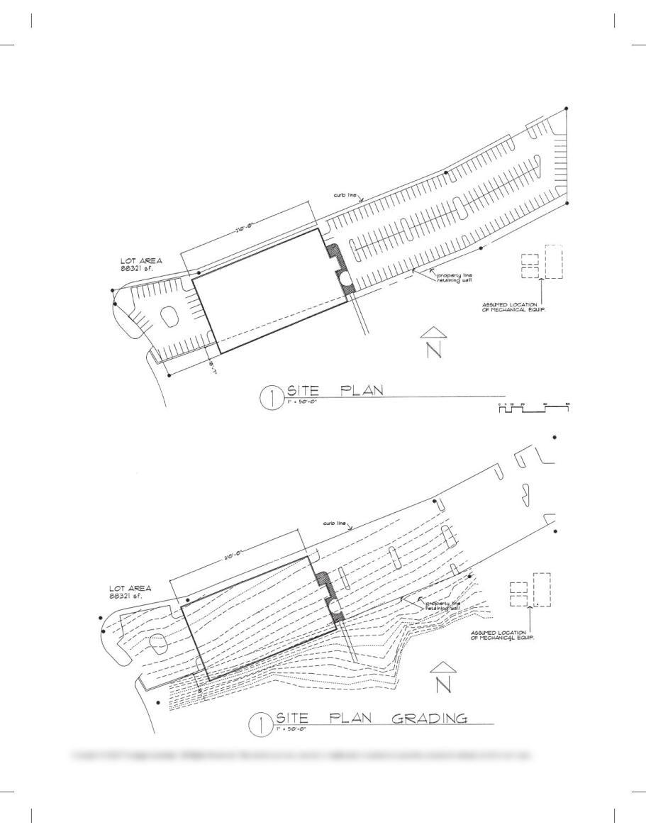
PROBLEM 24.18 Paving site plan
Use the graphic scale shown in the layout below to take
measurements. Convert to a scale of 10 5 609 on an appropriately
sized sheet.
Courtesy Soderstrom Architects, PC.
PROBLEM 24.19 Grading plan
Follow the same instruction as in Problem 24.18.
59728_ch24_EOC_ptg01.indd 10 03/02/16 10:38 am
Part 3: Problems 24.20 Through 24.26
Draw the plot plans from the given sketches or layouts.
PROBLEM 24.20
E
EL 104′ EL 100′
EL 108′ 334 . 43′
50 00′ 20″ E
EL 86′
PROVIDE WATER WELL
100′ MINIMUM TO
SEPTIC SYSTEM
A
N
BA AREA ACCEPTABLE
FOR SEPTIC SYSTEM
B AREA UNACCEPTABLE
FOR SEPTIC SYSTEM
652 . 65′
652 . 46′
N 89 31′ 45″ W
N 89 26′ 35″ W
EE333.44′
SOUTH BROOKS LN.
TAX LOT 2300, LOT 12 CLARKES ESTATES
SECTION 17, T. 4 S., R. 3E., SALT LAKE
MERIDIAN, TOOELE COUNTY, UTAH
PROBLEM 24.21
15′
15′
54.8′
54.8′
LOT 17, BLOCK 3, PLAT OF
GARTHWICK, YOUR CITY,
COUNTY, STATE
SS
MANCHESTER DRIVE
147 . 8′
167 . 8′
UTILITY
ALLEY
R = 10′
R = 10′
PROBLEM 24.22
N 08 48′ 40″ W
N 08 48′ 30″ W
LOT 7, BLOCK 2, KYLEE ESTATES
SECTION 12, T. 12 N., R. 14 E., LOUISIANA
MERIDIAN, RAPIDES PARISH, LOUISIANA
JASAN ROAD
SS
GG
WW
EE
EL 84′ EL 86′
EL 88′
EL 90′
138 . 87′
138 . 83′
219 . 64′
S 85
8
12′ 37″ E
141 . 31′
S 40
8
45′ 41″ W
313 . 30′
N 848 44′ 19″ E
EL 91′
N
PROBLEM 24.23
LOT 29
BLOCK 1
ASHDOWN WOOD
YOUR CITY, COUNTY
S TAT E
S 27′ 11′ 30″ W
290.69′
S 86′ 37′ 50″ E
487.19′
N 55′ 37′ 07″ W
100′
N 23′ 50′ 08″ W
324.46′
S 73’17’25” W
76′
NORTH
P. O . B .
ST. JAMES PLACE
RADIUS LENGTH: 75.31′
59728_ch24_EOC_ptg01.indd 11 03/02/16 10:38 am
PROBLEM 24.24
S 86′ 00′ 10″ E
202.98′
P. O . B .
LOT 15
BLOCK 3
BARRINGTON HEIGHTS
YOUR CITY, COUNTY
S TAT E
S 68′ 40′ 44″ W
30′
N 89′ 49′ 16″ W
209.15′
S 12′ 59′ 17″ W
79.43′
N 27′ 15′ 49″ E
RIVERKNOLL COURT
25′
C
L
114.52′
NORTH
PROPERTY LINE N 318 59′ 23″ E
N 34
8
42′ 27″ E 153.62′
PROPERTY LINE
LOT 23 OF TRACT # 366Ø
BLOCK # 144
HARBOR VIEW ESTATES
YOUR CITY, COUNTY, STATE
NORTH
d 28 32′ 5Ø” L 87.58′ R 197Ø.ØØ’
HARBOR VIEW DRIVE
d 2
8
23′ 24″ L 8Ø.ØØ’ R 1917.87′
SETTING SUN DRIVE
159.17′
PROBLEM 24.25
LOT 25
BLOCK 4
BARRINGTON HEIGHTS
YOUR CITY, COUNTY
S TAT E
N 45′ 05′ 24″ W
160.0′
S 44′ 54′ 36″ E
51.12′
NORTH
P. O . B .
EAST
190.63′
C
L
N 44′ 54′ 36″ W
29.05′
21.12′
N 12′ 59′ 17″ E
R=170
‘
135.25′
30′
B
A
R
R
I
N
G
T
O
N
D
R
I
V
E
PROBLEM 24.26
59728_ch24_EOC_ptg01.indd 12 03/02/16 10:38 am
Part 4: Problems 24.27 and 24.28
PROBLEM 24.27 Draw the complete site plan shown.
59728_ch24_EOC_ptg01.indd 13 03/02/16 10:38 am