
CHAPTER 23 HEATING, VENTILATING,
AND AIR-CONDITIONING (HVAC), AND
PATTERN DEVELOPMENT PROBLEMS
INSTRUCTIONS
Read all related instructions before you begin working. Specific
information is provided for each problem.
DRAFTING
TEMPLATES
To access CADD template files
with predefined drafting
settings, go to the Student
Companion Website, select
Student Downloads, Drafting
Templates, and then select
the appropriate template file.
59728_ch23_EOC_ptg01.indd 1 03/02/16 10:38 am
HVAC PLANS
Part 1: Problems 23.1 Through 23.3
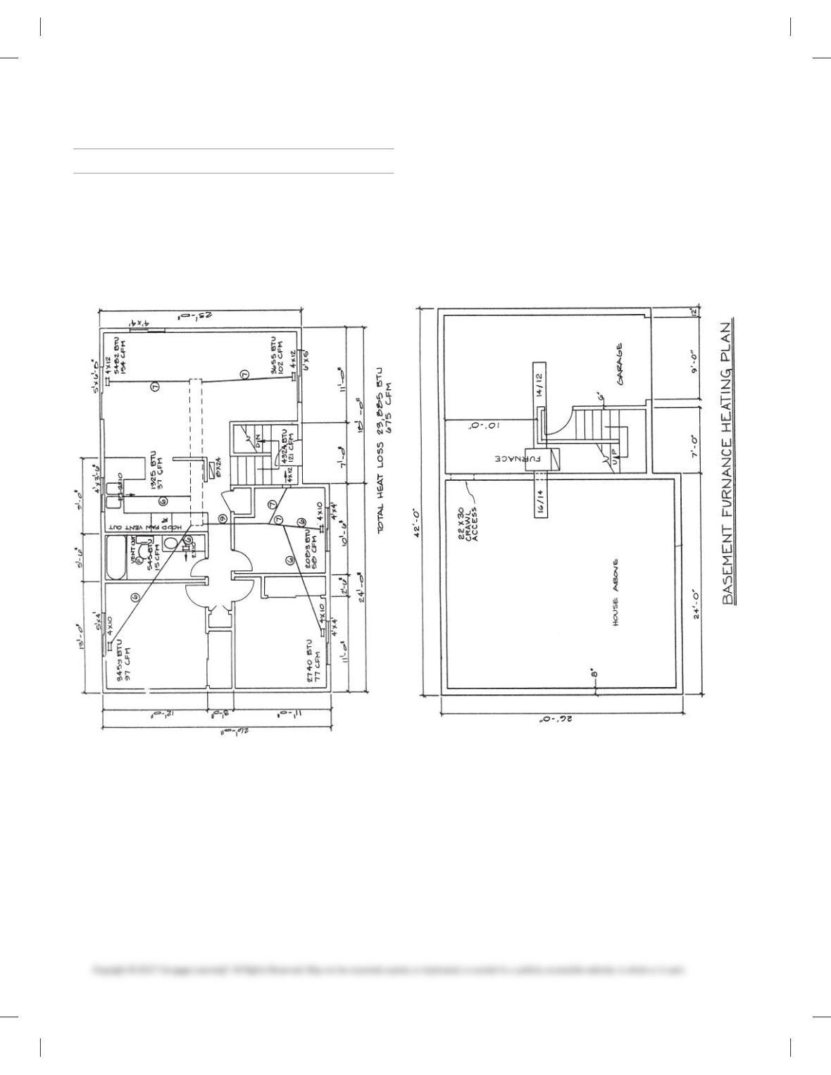
PROBLEM 23.1 Residential HVAC plan
Given: Residential heating engineering sketch of a main floor
plan and basement. Do the following on appropriately sized
sheets with a border and an architectural-style title block, unless
otherwise specified by your instructor. Two B-size sheets or one
C-size sheet are recommended.
1. Make a formal double-line HVAC floor plan layout at a
1/405 19-00 scale.
2. Approximate the location of undimensioned items such as
windows.
3. Place drawing features on unique layers using the AIA layer
standard names where possible. Use thin lines for the floor
plan layout and use thick lines for the heating equipment
and duct runs unless otherwise specified by your instructor
or supervisor.
59728_ch23_EOC_ptg01.indd 2 03/02/16 10:38 am
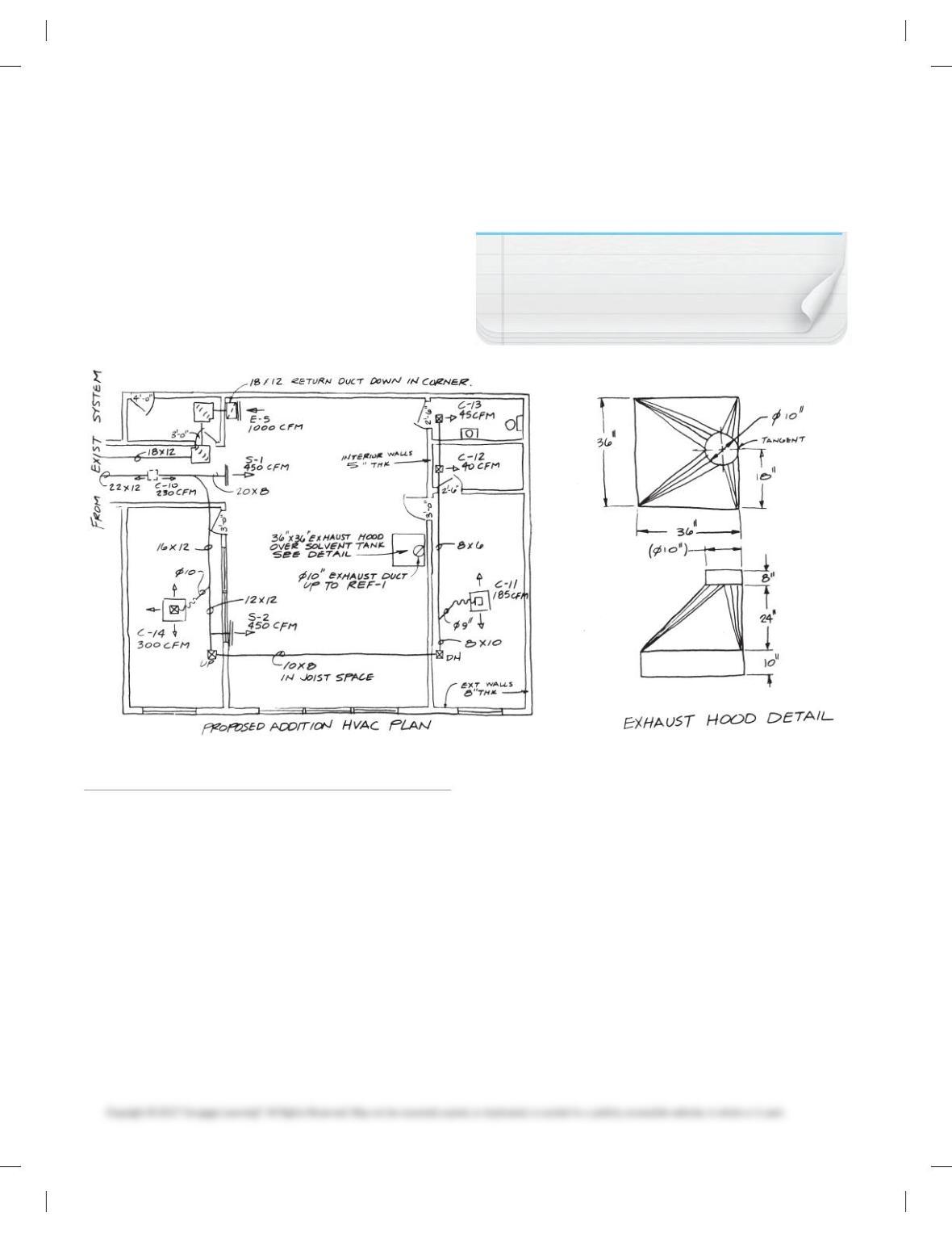
PROBLEM 23.3 Commercial HVAC plan
You are given the following:
1. An HVAC floor plan engineering layout is at approximately
1/1605 19-09. The engineer’s layout is rough, so round off
dimensions to the nearest convenient units at 60 intervals.
For example, if the dimension you scale reads 24 ft. 3 in.,
then round off to 24 ft. 0 in. The floor plan does not require
dimensioning, so the representation is more important than
the specific dimensions.
2. Related schedules.
3. Engineer’s sketch for exhaust hood.
Do the following on appropriately sized sheets with borders and
architectural-style title blocks, unless otherwise specified by
your instructor. A D-size sheet is recommended. All required
items can fit on one sheet with careful planning.
1. Make a formal double-line HVAC floor plan layout at a 1/405
19-00scale. (Note: You measured the given engineer’s sketch
at 1/1605 19-00.) Now convert the established dimensions to
a formal drawing at 1/405 19-00. Approximate the location of
the HVAC duct runs and equipment in proportion to the
presentation on the sketch. Assume that the given single-
line sketch represents the centerline of the ducts.
SCHEDULES
CEILING OUTLET SCHEDULE
Symbol Size CFM Damper Type Panel Size
C-10 9 39 240 Key operated 12 312
C-11 8 38 185 Key operated 12 312
C-12 6 36 40 Key operated 12 312
C-13 6 36 45 Key operated 12 312
C-14 6 318 300 Fire damper 24 324
SUPPLY GRILL SCHEDULE
Symbol Size CFM Location Damper Type
S-1 20 38 450 High wall Key operation
S-2 12 312 450 High wall External operation
EXHAUST GRILL SCHEDULE
Symbol Size CFM Location Damper Type
E-5 18 324 1000 Low wall No damper
ROOF EXHAUST FAN SCHEDULE
Symbol Area Served CFM Fan Specifications
REF-1 Solvent Tank 900 1/4 HP, 12 IN nonspark wheel,
1050 max. outlet velocity
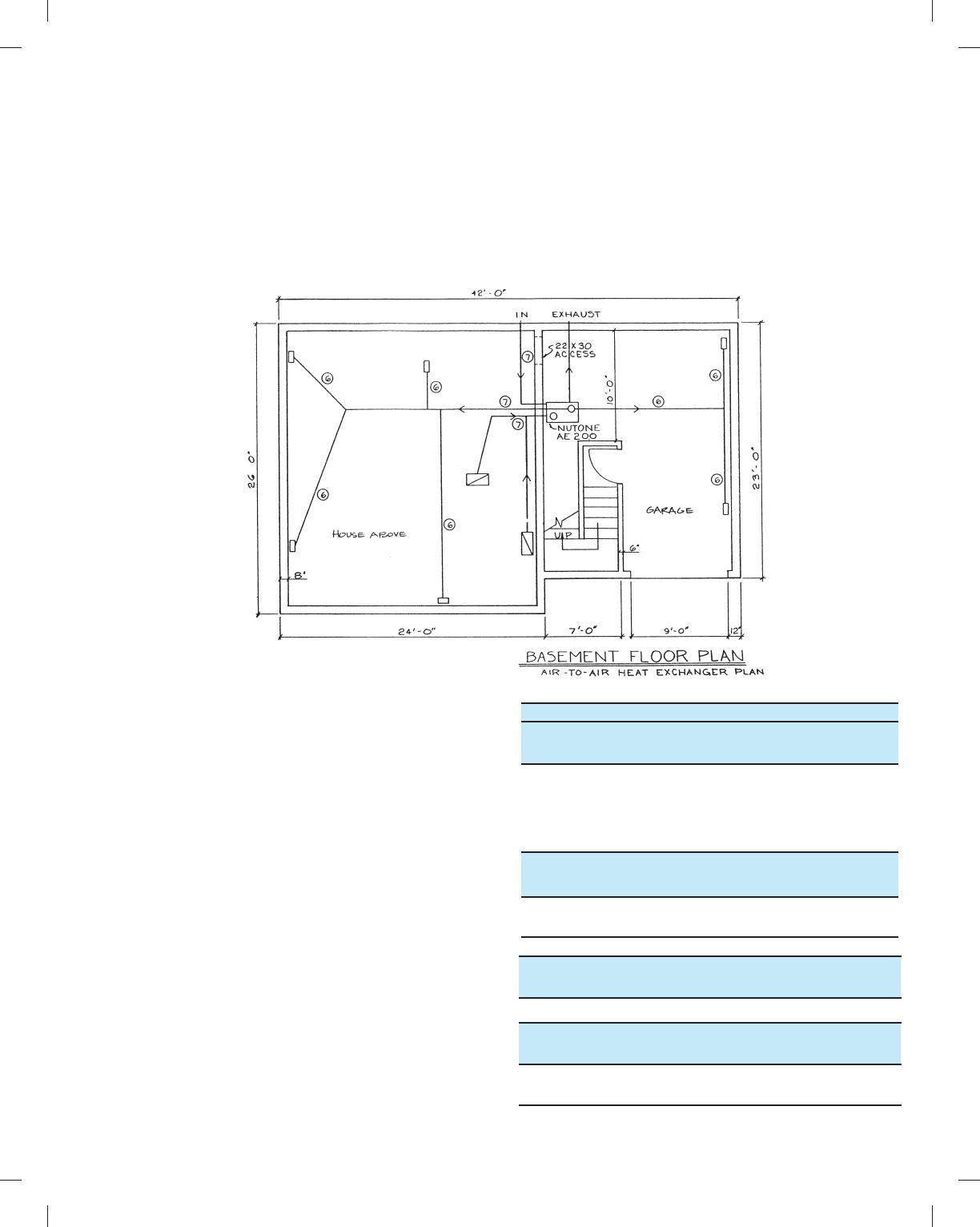
PROBLEM 23.2 Residential air-to-air heat exchanger plan
Given: Residential air-to-air heat exchanger ducting engineering
sketch of a basement floor plan. Do the following on appropri-
ately sized sheets with a border and an architectural-style title
block, unless otherwise specified by your instructor. One B- or
C-size sheet is recommended.
1. Make a formal single-line air-to-air heat exchanger floor
plan layout at a 1/405 19-00 scale.
2. Approximate the location of undimensioned items such as
doors.
3. Place drawing features on unique layers using the AIA layer
standard names where possible. Use thin lines for the floor
plan layout and use thick lines for the air-to-air heat ex-
changer equipment and duct runs.
59728_ch23_EOC_ptg01.indd 3 03/02/16 10:38 am
Part 2: Problems 23.4 and 23.5
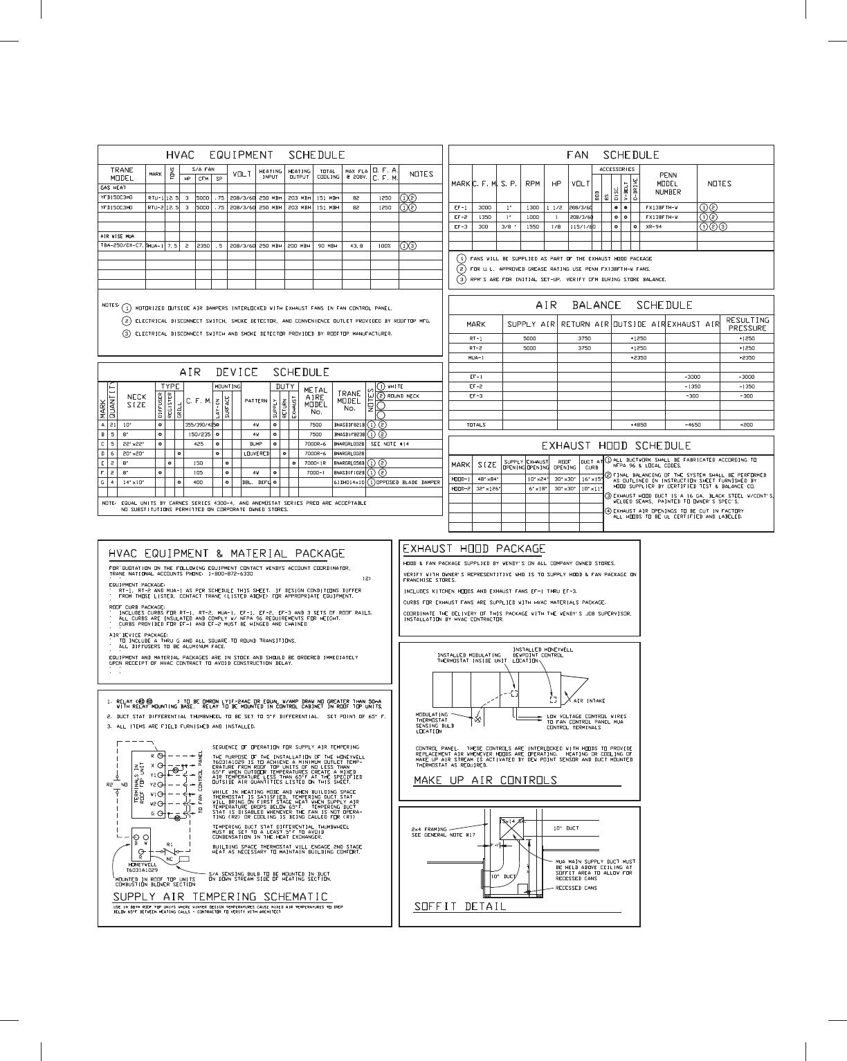
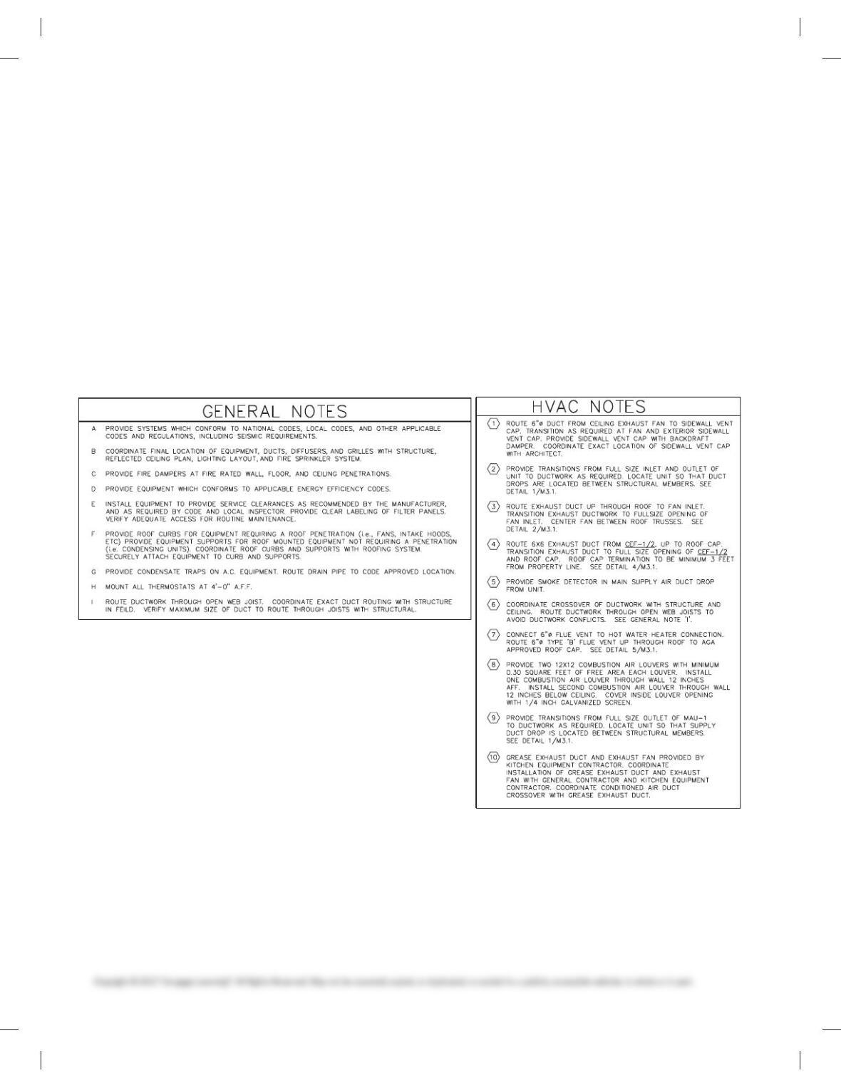
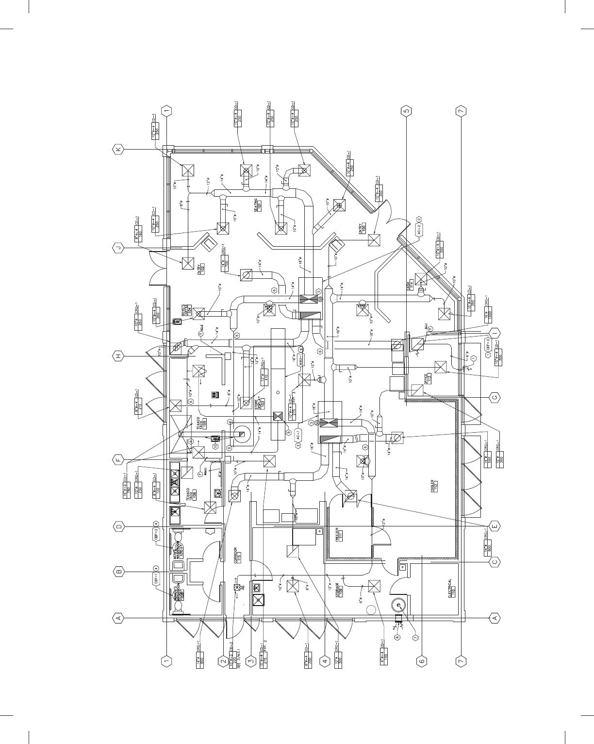
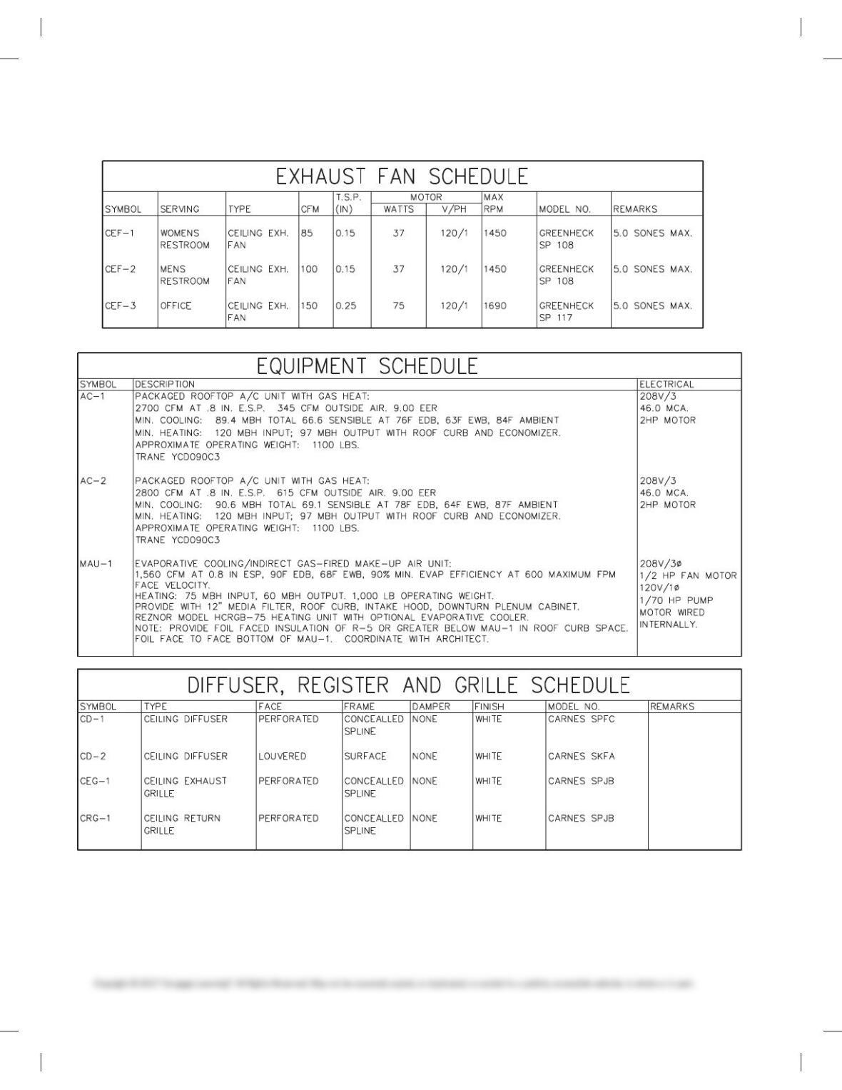
PROBLEM 23.4 Commercial HVAC plan
Problem courtesy Wendy‘s International, Inc.
Given the following:
1. HVAC floor plan single-line engineering layout at approxi-
mately 1/80 5 19-00. The provided problem is rough, so
round off to the nearest convenient units at 60 intervals. For
example, if a dimension reads 249-30, round off to 249-00 or
249-60 as you prefer. The floor plan does not require dimen-
sioning; therefore, the representation is more important
than the actual dimensions.
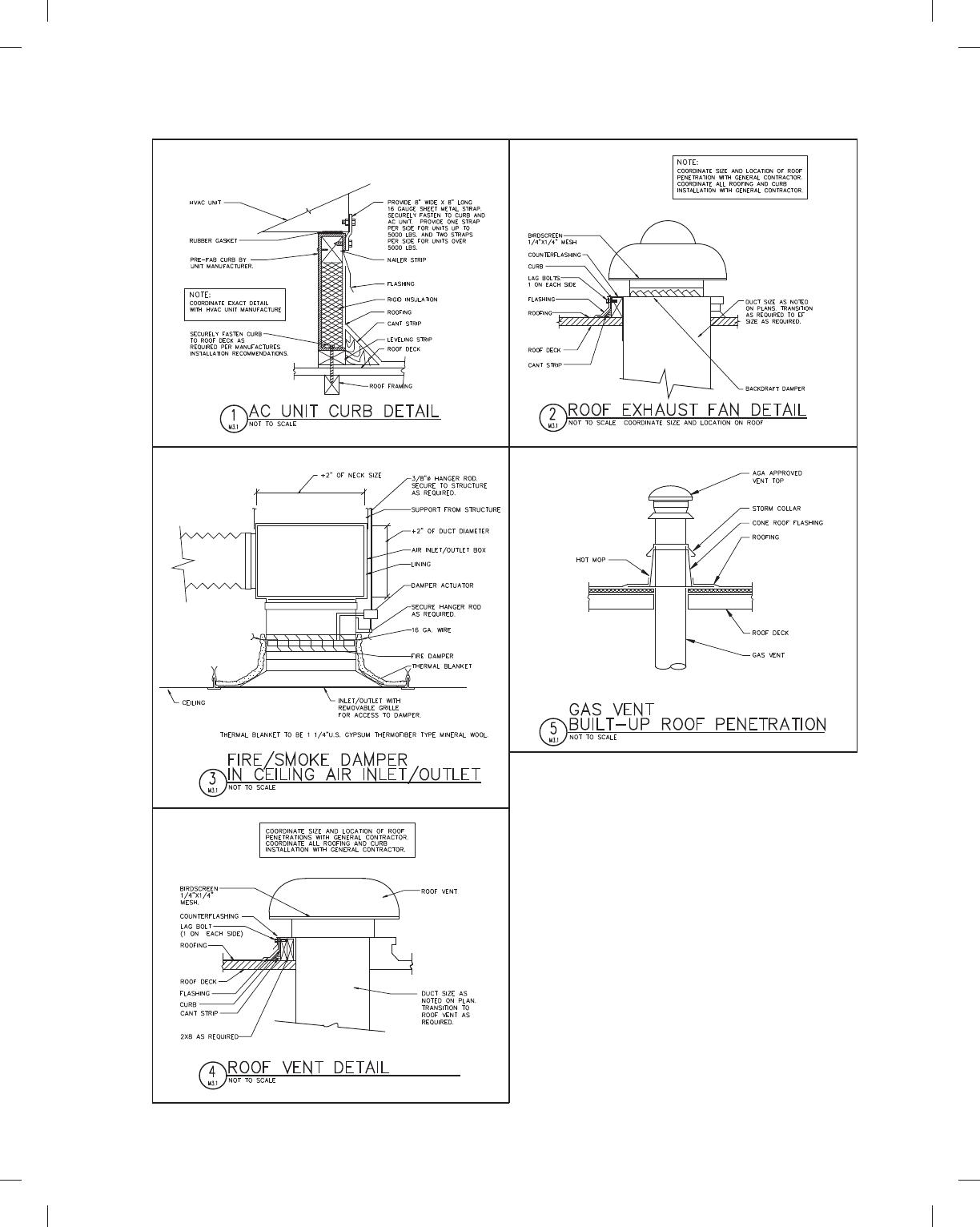
2. Related general notes, schedules, schematics, and details.
NOTE: Do not include notes and dimensions for
wall thickness, door sizes, and tangent. Top view
of exhaust hood detail is drawn as a transition
piece, similar to Figure 23.68.
2. Prepare correlated schedules in the space available. Set
up the schedules in a manner similar to the examples in
Figure 23.23, page 870, for layout.
3. Make a detail drawing of the exhaust hood either scaled or
unscaled. Make the detail large enough to clearly show the
features. Refer to Figure 23.20, pages867–868, for an example
of a detail drawing.
4. Approximate the location of doors, windows, and fixtures.
5. Place drawing features on unique layers using the AIA layer
standard names where possible. Draw the floor plan layout
using thin lines and the HVAC components with thick lines
for contrast.
Do the following on an appropriately sized sheet or sheets:
1. Make a formal double-line HVAC floor plan at a scale of
1/40 5 19-00. (Note: You measured the given plan using a
1/80 5 19-00 scale. Use the established dimensions to create
the formal drawing at a scale of 1/4 5 19-00.) Approximate
the location of the HVAC duct runs and equipment in pro-
portion to the presentation given on the engineering layout.
Assume that the single-line layout is the centerline of the
ducts.
2. Approximate the location and size of doors, windows, and
fixtures.
59728_ch23_EOC_ptg01.indd 4 03/02/16 10:38 am
PROBLEM 23.4
(Continued )
59728_ch23_EOC_ptg01.indd 5 03/02/16 10:38 am

GENERAL NOTES:
1) HVAC SYSTEM DESIGNED TO MEET OUTSIDE TEMP OF 93 DEGREES F SUMMER
AND 0 DEGREES F WINTER. CONTACT ‘TRANE NATIONAL ACCOUNTS’ FOR
REQUIREMENTS ATOTHER TEMPERATURE CONDITIONS.
2) PROVIDE 1 YEAR WARRANTY ON WORKMANSHIP AND ON EQUIPMENT BY
MECHANICAL CONTRACTOR. 1 YEAR PARTS, 5 YEAR COMPRESSOR, AND
10 YEAR HEAT EXCHANGER WARRANTIES ON THE ROOFTOP UNITS BY
MANUFACTURER.
3) INSULATED FLEXIBLE DUCT MAY BE USED IN MAXIMUM LENGTHS OF 7′-0” PER
BRANCH RUN. THE BALANCE OF THE RUN SHALL BE HARD PIPE W/1”
INSULATED SLEEVE. FLEXIBLE DUCT SHALL BE OWENS CORNING INL. 25 OR
EQUAL.
4) SPIN-IN FITTING W/ DAMPER SHALL BE FLEXAIRE RF OF METALAIRE MBSD.
TYPICAL OF ALL BRANCH DUCT RUNS.
5) ALL DUCTWORK TO BE RUN ABOVE THE SUSPENDED CEILING.
6) HVAC CONTRACTOR TO RECEIVE AND SET ROOF MOUNTED CONDENSING
UNITS AND PROVIDE MOUNTING RAILS. REFER TO STRUCTURAL PLAN 8 FOR
LOCATIONS OF ROOF MOUNTED EQUIPMENT, CURB, AND RAIL DETAILS.
7) DUCTWORK SHOWN IS FINISHED O. D. DIMENSION AND TO BE INSULATED
W/ 1 1/2” DUCT WRAP, INCLUDING DIFFUSERS.
8) RETURN DROPS FROM RT-1 AND RT-2 TO BE LINED, PINNED, AND GLUED W/1”
INSULATION PER INDUSTRY STANDARDS.
9) COMPLETED INSTALLATIONS SHALL CONFORM TO ALL APPLICABLE LOCAL,
STATE, AND FEDERAL CODES AND ORDINANCES, INCLUDING, BUT NOT
LIMITED TO THE LATEST EDITIONS OF THE FOLLOWING STATE BUILDING
CODE, NFPA–90A, NFPA-96 AND NFPA–101.
10) SUPPLY AND RETURN AIR DUCT DROPS FROM ROOF TOP UNITS TO BE
ISOLATED FROM UNIT VIBRATION WITH FLEXIBLE DUCT CONNECTORS.
11) ALL SUPPLY & RETURN AIR DUCTS AND DIFFUSERS ARE TO BE INSULATED.
12) RUN 18/8 THERMOSTAT WIRE FROM FAN CONTROL PANEL TO ROOFTOP
UNITS AND 18/2 THERMOSTAT WIRE TO OUTSIDE AIR DAMPER.
13) HVAC CONTRACTOR TO TEST CHECK AND BALANCE ALL ROOFTOP UNITS,
EXHAUST HOODS. EXHAUST FANS AND DIFFUSERS TO SPECIFIED CFM’S AND
SUBMIT A WRITTEN REPORT TO THE OWNER.
14) “C” DIFFUSERS TO HAVE 22″ X 22″ BOX FIELD FABRICATED W/12″ COLLAR
INSTALLED INSIDE OF BOX. TO BE FIELD MEASURED FOR 12″ HEIGHT.
15) THERMOSTATS ARE PROVIDED BY ELECTRICIAN IN FAN CONTROL PANEL (SEE
SHEET #14). HVAC CONTRACTOR TO MOUNT REMOTE SENSORS AND RUN
CONTROL WIRES FOR STATS AND SENSORS OUTSIDE OF THE FAN CONTROL
PANEL.
16) ALL CURBS TO BE ONE PIECE WELDED AND INSULATED 18 GA STEEL. 1 1/2″
RIGID INSULATION GLUED TO INSIDE OF CURB. ALL CURBS TO HAVE 1 1/2″
WOOD NAILER ATTACHED TO TOP OF CURB.
17) FRAMING IN THIS AREA TO BE DOUBLE 2X4 @17 1/2″ D.C. TO
ACCOMMODATE AIR DEVICE PENETRATIONS.
18) ALL 90 DEGREE BENDS IN SUPPLY AIR DUCTS TO HAVE TURNING VANES. THE
DISMANTLING OF ANY DUCT WILL BE REQUIRED TO VERIFY VANES.
19) ALL DUCT WORK IS TO BE INSTALLED PER ANSI SPECIFICATIONS.
20) PIEZO ALERTS FOR SMOKE DETECTORS INSTALLED BY HVAC CONTRACTOR
MOUNTING LOCATION SHOWN ON ELECTRICAL PLAN.
21) HVAC CONTRACTOR TO SUPPLY AND INSTALL WIRE FOR THERMOSTAT AND
SMOKE DETECTOR CIRCUITS.
22) HVAC CONTRACTOR TO CONNECT MUA-1 LOW VOLTAGE CONTROL
TERMINALS TO CONTROL PANEL TERMINALS.
PROBLEM 23.4
(Continued )
3. Prepare correlated general notes and schedules.
4. Create the necessary schematic and detail drawings with
their correlated notes and specifications.
5. Draw the floor plan using thin lines and the HVAC compo-
nents with thick lines for contrast. Use appropriate CADD
layers.
59728_ch23_EOC_ptg01.indd 6 03/02/16 10:38 am
PROBLEM 23.4
(Continued )
59728_ch23_EOC_ptg01.indd 7 03/02/16 10:38 am
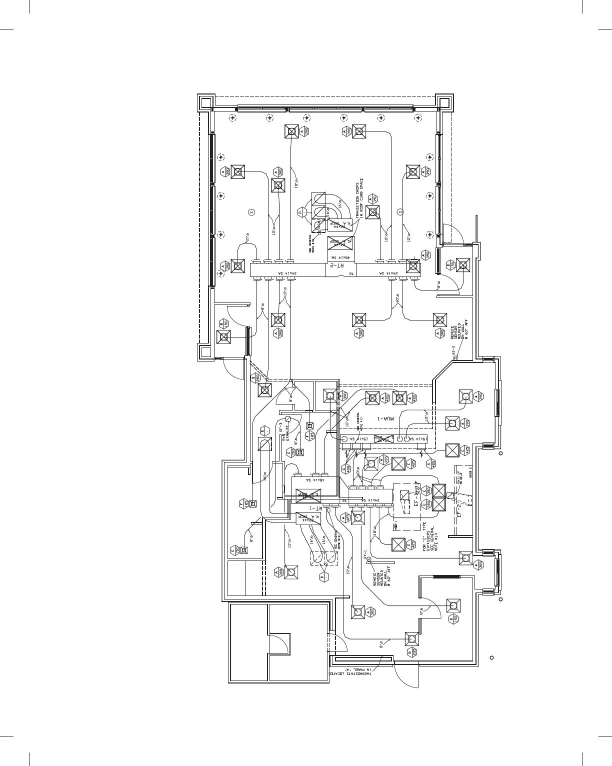
PROBLEM 23.5 Commercial HVAC plan
Problem courtesy Interface Engineering.
Given the following:
1. HVAC floor plan single-line engineering layout at approxi-
mately 1/80 5 19-00. The provided problem is rough, so
round off to the nearest convenient units at 60 intervals. For
example, if a dimension reads 249-30, round off to 249-00 or
249-60 as you prefer. The floor plan does not require dimen-
sioning; therefore, the representation is more important
than the actual dimensions.
2. Related general notes, schedules, schematics, and details.
Do the following on an appropriately sized sheet or sheets:
1. Make a formal double-line HVAC floor plan at a scale of
1/40 5 19-00. (Note: You measured the given plan using a
1/80 5 19-00 scale. Use the established dimensions to create
the formal drawing at a scale of 1/40 5 19-00.) Approximate
the location of the HVAC duct runs and equipment in pro-
portion to the presentation given on the engineering layout.
Assume that the single-line layout is the centerline of the
ducts.
2. Approximate the location and size of doors, windows, and
fixtures.
3. Prepare correlated general notes and schedules.
4. Create the necessary schematic and detail drawings with
their correlated notes and specifications.
5. Draw the floor plan using thin lines and the HVAC compo-
nents with thick lines for contrast. Use appropriate CADD
layers.
59728_ch23_EOC_ptg01.indd 8 03/02/16 10:38 am
PROBLEM 23.5
(Continued )
59728_ch23_EOC_ptg01.indd 9 03/02/16 10:38 am
PROBLEM 23.5
(Continued )
59728_ch23_EOC_ptg01.indd 10 03/02/16 10:38 am
PROBLEM 23.5
(Continued )
59728_ch23_EOC_ptg01.indd 11 03/02/16 10:38 am
PATTERN DEVELOPMENT
Part 3: Problems 23.6 Through 23.14
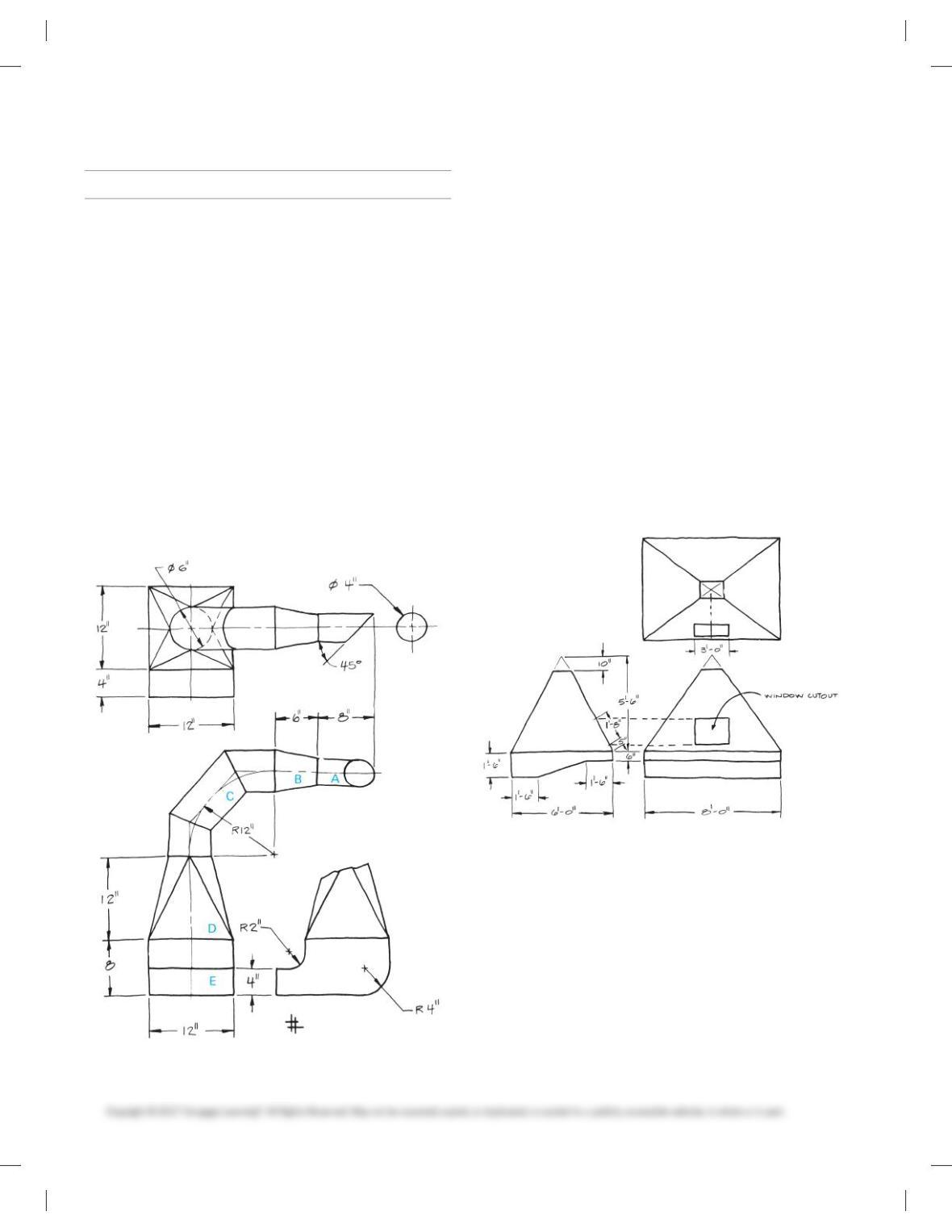
PROBLEM 23.6 Exhaust duct system (in.)
Given: The engineer’s sketch and specifications for an exhaust
duct system. The sketch displays the top, front, and partial left
side views of an exhaust duct system that could be found in any
commercial solid-fuel exhaust. The exhaust pickup is rectangu-
lar in shape, and the discharge throat is cylindrical. The direc-
tional path of the system is often obstructed and closely confined
for reasons of design and operation of the system.
Do the following on an appropriately sized sheet or sheets
with border and architectural-style title blocks:
1. Make a pattern development for each of the five exhaust
duct components. There are five individual pattern develop-
ment drawings:
a. Truncated cylinder
b. Truncated cone
c. Three-piece elbow
d. Square-to-round transition piece
e. Rectangular transitional elbow
2. Use full scale unless otherwise specified by your instructor.
Use a 3/8 in. single-lap seam on individual parts and be-
tween adjacent parts.
3. Show all layout and construction. Do not turn off or freeze
your construction layer unless otherwise specified by your
instructor.
PROBLEM 23.7 Welding booth hood (in.)
Given: The engineer’s sketch of a fabrication shop’s welding
booth hood. Do the following on an appropriately sized sheet or
sheets with border and architectural-style title blocks:
1. Make a pattern development drawing of the pyramid-
shaped hood and the shroud base at full scale, unless other-
wise specified by your instructor.
2. Provide the cutout for the window to be added later. Be
careful to find the true location and true size and shape of
the cutout in the pattern.
3. No seam material allowance is required because the seams
are welded.
4. Show all layout and construction on a construction layer.
59728_ch23_EOC_ptg01.indd 12 03/02/16 10:38 am
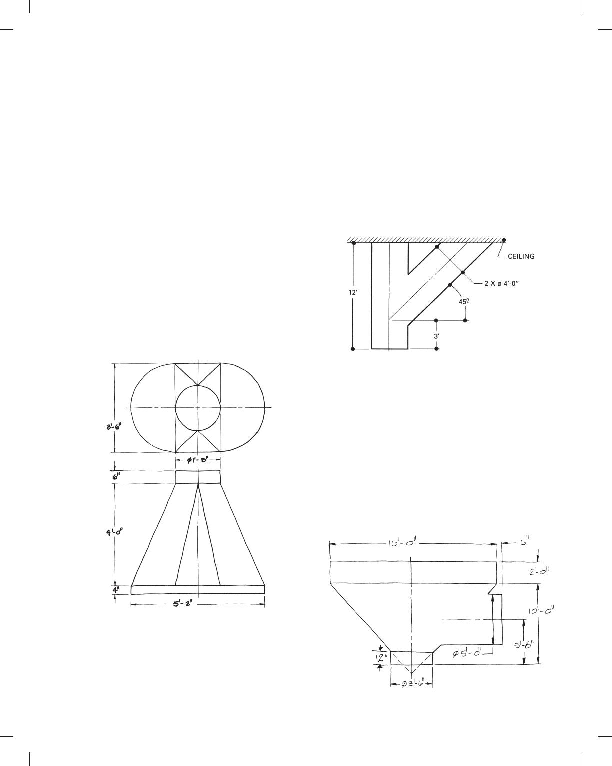
PROBLEM 23.10 Cylindrical duct intersection (in.)
Given: The engineer’s computer sketch of intersecting cylindri-
cal ducts. Do the following on an appropriately sized sheet or
sheets with a border and architectural-style title blocks:
1. Use full scale, unless otherwise specified by your
instructor.
2. Find the intersection between the cylindrical ducts.
3. Make a pattern development for each cylinder.
4. Use a 1 in. (scale) double-lap seam.
5. Show all layout and construction using a construction
layer.
PROBLEM 23.8 Exhaust hood (in.)
Given: The exhaust hood detail from Problem 23.3. Do the fol-
lowing on an appropriately sized sheet or sheets with border and
architectural-style title blocks:
1. Make a pattern development on appropriately sized layout
for the transition piece, the top collar, and the base collar.
2. Use full scale, unless otherwise specified by your instructor.
3. Provide a 1 in. single-lap seam for each part and between
adjacent parts.
4. Show all layout and construction using a construction layer.
PROBLEM 23.9 Chemistry laboratory hood (in.)
Given: The engineer’s rough sketch of the chemistry laboratory
hood. Do the following on an appropriately sized sheet or sheets
with a border and architectural-style title blocks:
1. Make a pattern development drawing of the chemistry labo-
ratory hood, including the top and bottom collars.
2. Use full scale, unless otherwise specified by your
instructor.
3. No seams required.
4. Show all layout and construction using a construction layer.
PROBLEM 23.11 Grain hopper (in.)
Given: The engineer’s sketch of the grain hopper. Do the follow-
ing on an appropriately sized sheet or sheets with a border and
architectural-style title blocks:
1. Use full scale, unless otherwise specified by your
instructor.
2. Determine the line of intersection between the cylinder and
the cone in both views.
3. Make the resulting pattern development of the cone and
side intersecting cylinder.
4. No seam material allowance required.
5. Show all layout and construction using a construction
layer.
59728_ch23_EOC_ptg01.indd 13 03/02/16 10:38 am
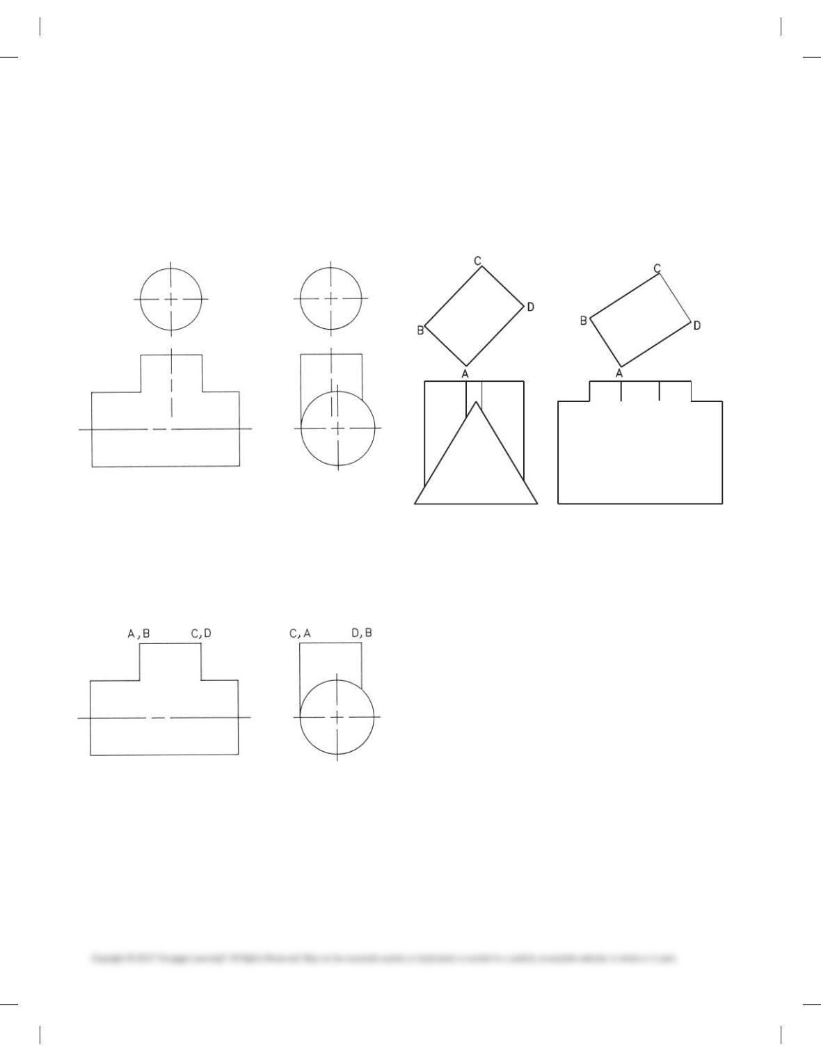
PROBLEM 23.12 Intersection
Given the following drawing, use a 1/405 19-00 scale to measure
the given drawing. Make a 100% print of the problem page and
use the hard copy to establish the dimensions. Make your draw-
ing full scale using the measurements, unless otherwise specified
by your instructor. Determine the line of intersection between
the parts. Show all construction using a construction layer.
PROBLEM 23.13 Intersection
Given the following drawing, use a 1/405 19-00 scale to measure
the given drawing. Make a 100% print of the problem page and
use the hard copy to establish the dimensions. Make your draw-
ing full scale using the measurements, unless otherwise specified
by your instructor. Determine the line of intersection between
the parts. Show all construction using a construction layer.
PROBLEM 23.14 Intersection
Given the following drawing, use a 1/405 19-00 scale to measure
the given drawing. Make a 100% print of the problem page and
use the hard copy to establish the dimensions. Make your draw-
ing full scale using the measurements, unless otherwise specified
by your instructor. Determine the line of intersection between
the parts. Show all construction using a construction layer.
59728_ch23_EOC_ptg01.indd 14 03/02/16 10:38 am
COMPLETE SEQUENCE OF HVAC
DRAWINGS
Part 4: Problem 23.15
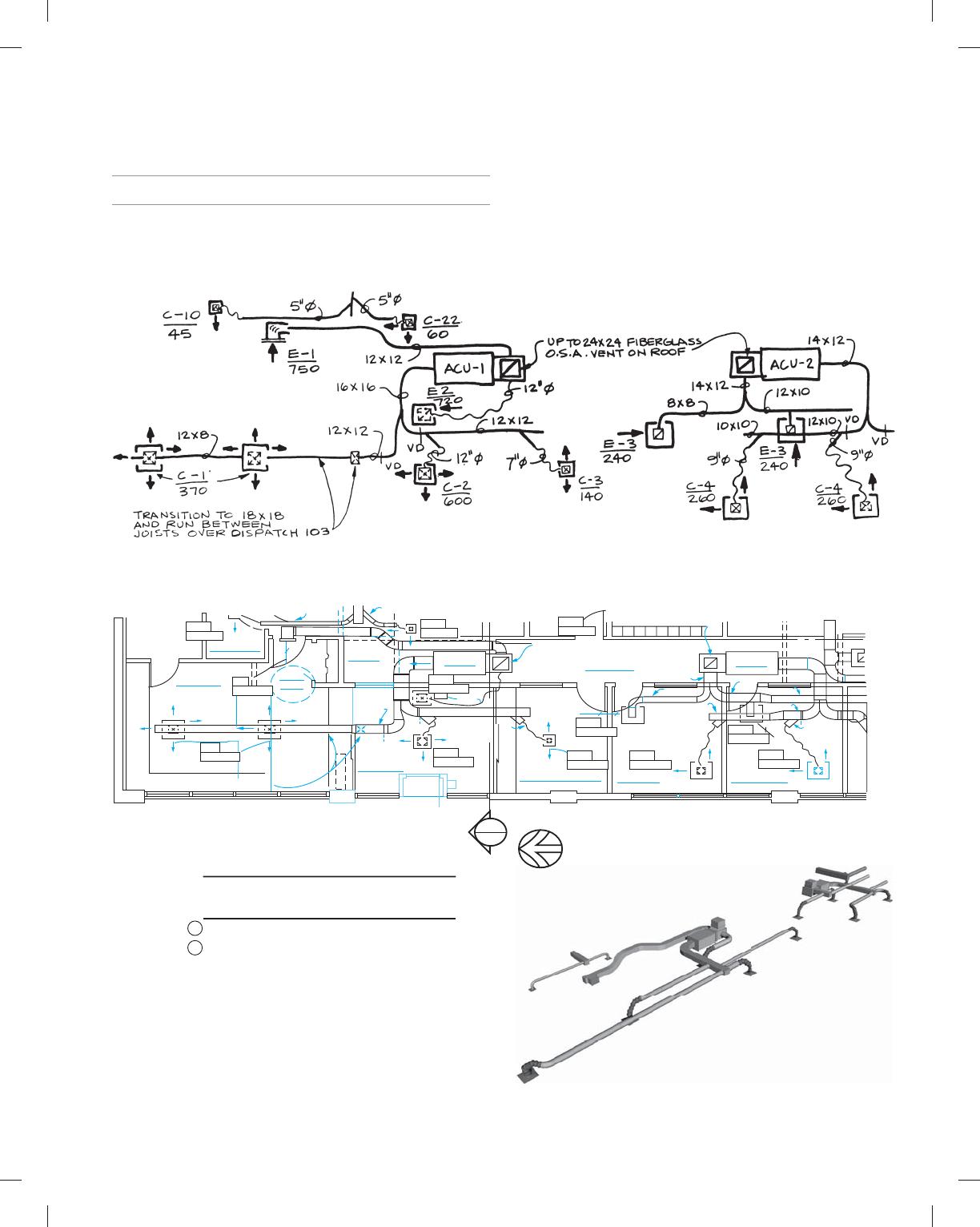
PROBLEM 23.15 Given the single-line engineering sketch
shown in Figure P23.15a, draw the HVAC contract drawing in
Figure P23.15b, the HVAC contractor 3-D model drawing in
Figure P23.15c, the HVAC contractor 2-D drawing in Figure
P23.15d, and the section in Figure P23.15e. Create the cover
sheets and cutsheets shown in Figure P23.15f. Establish dimen-
sions proportional to the given sketch and drawings.
SCALE: 1/4” = 1″-Ø”
1
FLOOR PLAN – MECHANICAL
TELECOMM
104
DISPATCH
103
VESTIBULE
101
LOBBY
102 ACU-1 CORRIDOR
135
MUNICIPAL COURT
125
SARGENT
124
LIEUTENANT
123
ACU-2
12 x 12
12 x 12
12 x 12
8 x 8
14 x 12
16 x 11
14 x 12
10 x 10
12 x 10
12 x 10
1O x 8
12 x 8 12″Ø
12″Ø
8″Ø
8″Ø
V. D.
V. D. V. D.
V. D.
TRANSITION TO 18 x 8 &
RUN BETWEEN JOISTS
OVER DISPATCH 103.
E-3
240 CFM
C-4
260 CFM
C-2
600 CFM
UP TO 24 x 24 FIBERGLASS
O.S.A. VENT ON ROOF
5″Ø 5″Ø
COND.
UNIT
#3
C-22
60 CFM
1
M-3
VERIFY ALL EXISTING CONDITIONS AT SITE.
SEE ARCHITECTURAL FLOOR PLAN FOR 1-HR
RATED AREAS. PROVIDE FIRE DAMPERS AS
SCHEDULED AND AS REQ’D BY CODE.
GENERAL NOTES:
2
E-2
250 CFM
E-3
240 CFM
C-3
140 CFM
C-4
260 CFM
E-8
50 CFM
C-10
45 CFM
E-1
750 CFM
C-1
370 CFM
UP TO 18 x 18 FIBERGLASS
O.S.A. VENT ON ROOF
Figure P23.15a
Figure P23.15b
Figure P23.15c
59728_ch23_EOC_ptg01.indd 15 03/02/16 10:38 am
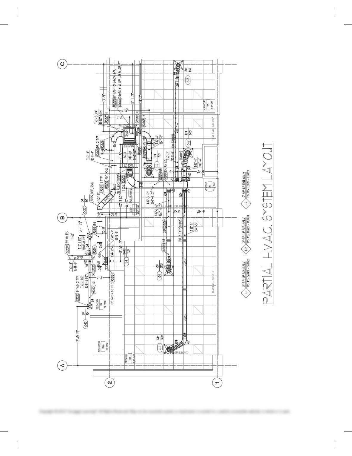
Figure P23.15d
59728_ch23_EOC_ptg01.indd 16 03/02/16 10:38 am
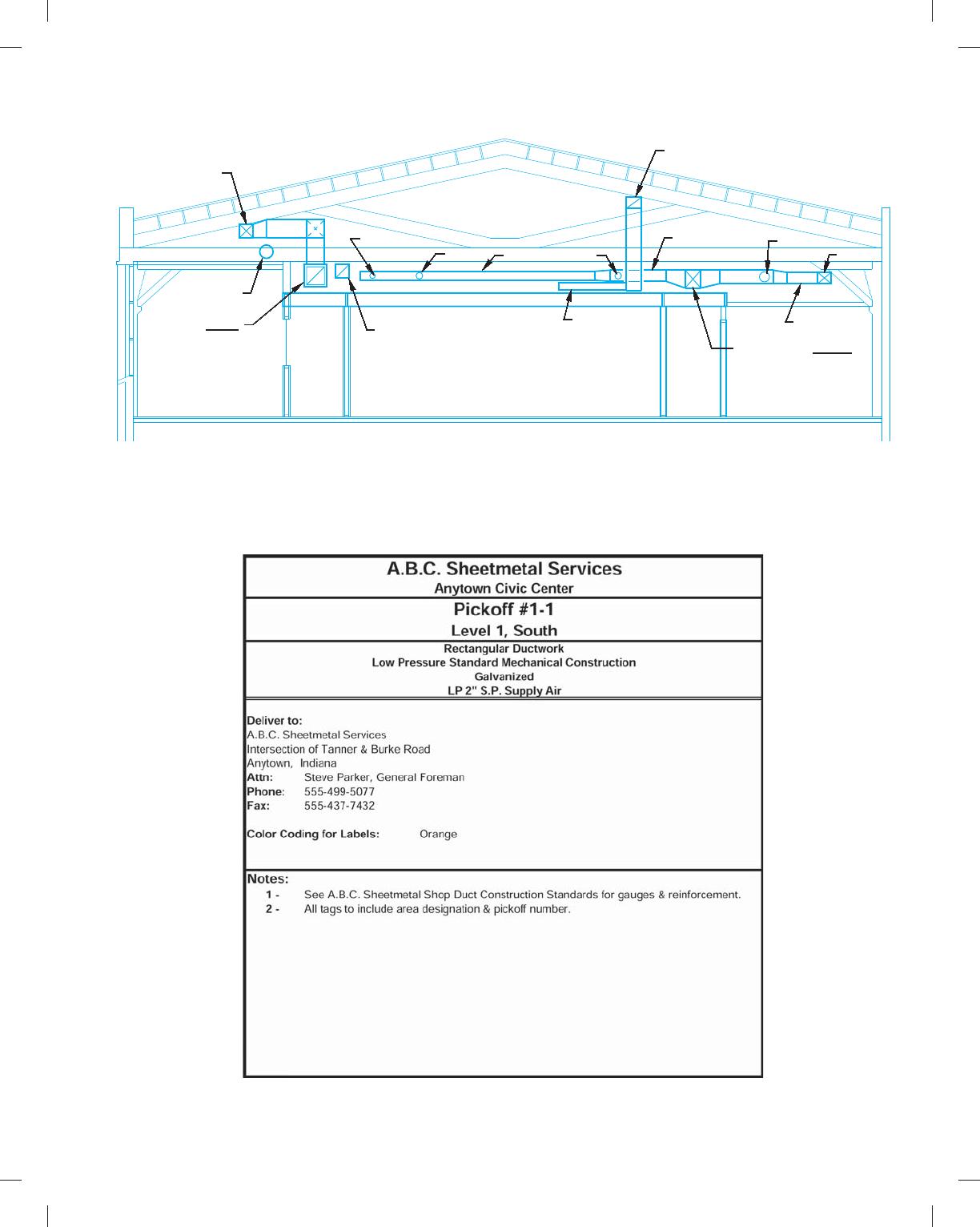
Figure P23.15f (continued )
12X12 SUPPLY
12″Ø RET AIR
ACU-1 12X12 RET AIR
5″Ø
6″Ø 8X10 6″Ø
6X10
14X10 RET AIR
10X10
12X14
16X14 FROM ACU-4
12X10
9″Ø
10X12
Figure P23.15e
59728_ch23_EOC_ptg01.indd 17 03/02/16 10:38 am
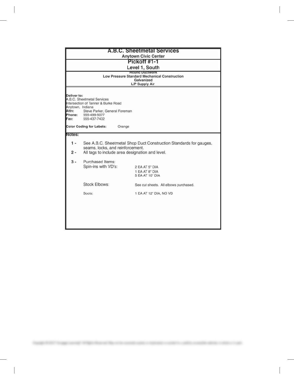
Figure P23.15f (continued )
59728_ch23_EOC_ptg01.indd 18 03/02/16 10:38 am
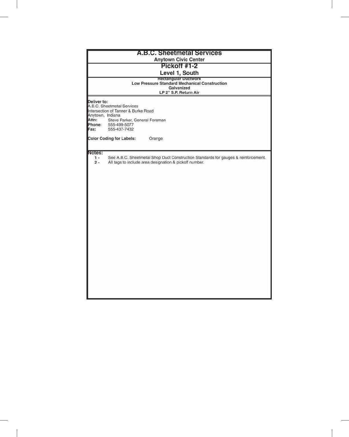
Figure P23.15f (continued )
59728_ch23_EOC_ptg01.indd 19 03/02/16 10:38 am
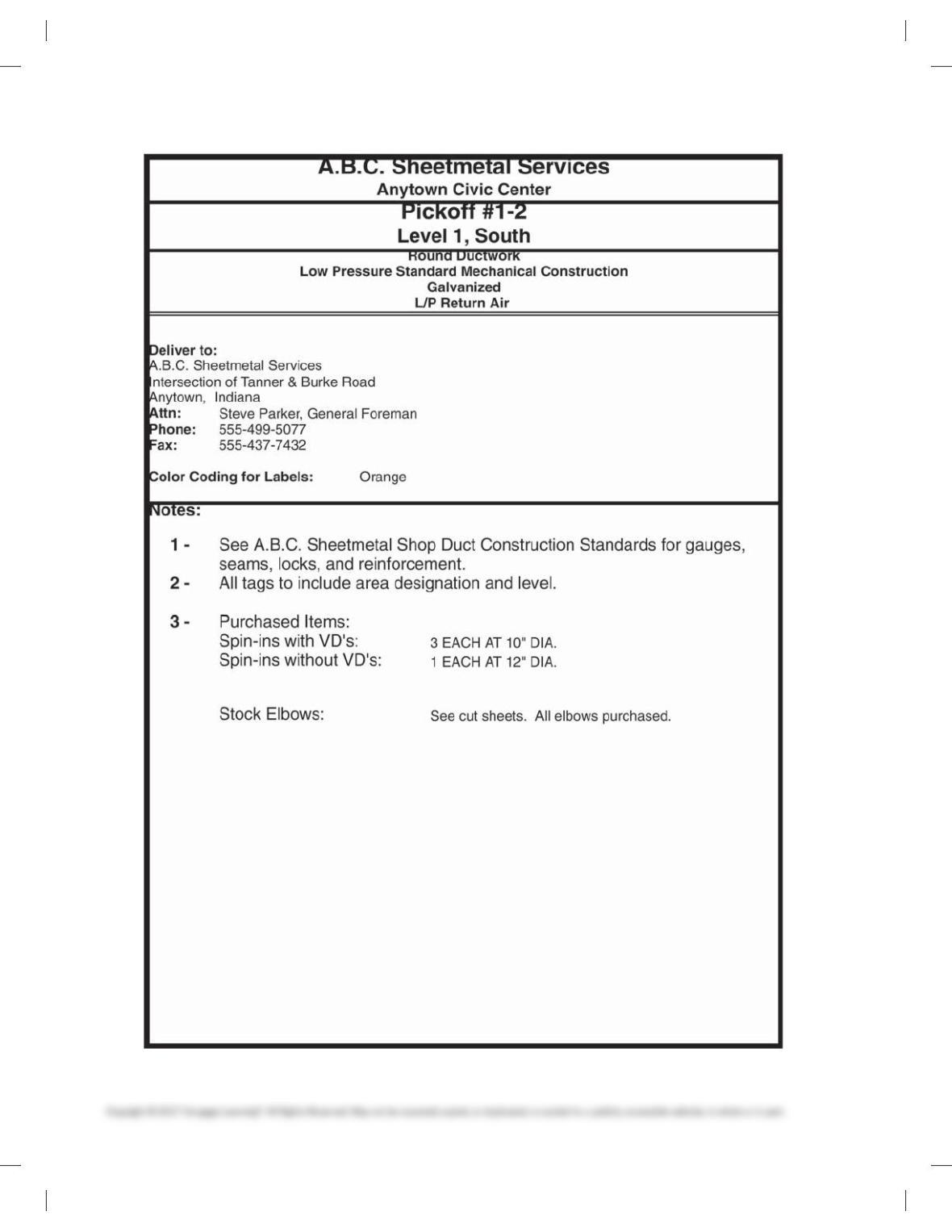
Figure P23.15f (continued )
59728_ch23_EOC_ptg01.indd 20 03/02/16 10:38 am