
2
CHAPTER 22 STRUCTURAL
DRAFTING PROBLEMS
INSTRUCTIONS
1. Read all related instructions before you begin working.
2. Use a Gothic, Arial, RomanS, or architectural font style.
Confirm the preferred text style with your instructor.
3. Use the engineering sketches to prepare a complete set of
drawings for the given problems.
4. Do all drawings on 220 3 340 or 240 3 360 (AI and AO metric)
sheets unless otherwise specified by your instructor. Use an
architectural-style border and title block, with the title block
along the right side of the sheet or along the bottom of the
sheet. Confirm the preferred border and title block with
your course guidelines.
5. Use proper sectioning and detailing techniques as corre-
lated to the engineering sketches. Some recommended
scales are provided. You can increase or decrease the scale,
depending on the available space and the complexity of the
section or detail. Sections and details should be drawn at a
minimum scale of 3/80 5 19-00 (1:20 metric). Judgment
should be used if a section or detail requires a lot of informa-
tion. A larger scale ranging from 3/40 to 1-1/20 5 19-00 (1:10
metric) should be considered.
6. It is recommended that you evaluate the entire set of
sketches for each problem before beginning to draw. Infor–
mation needed to draw one problem may be found on the
sketch or data for another problem or on another page or
view. The problems are real drafting situations, so you will
interpret rough engineering sketches and prepare formal
drawings using the best drafting techniques and standards
that you have learned.
7. It is suggested that drawing sheets be organized with as
much information as possible without crowding or
reducing clarity. If additional drawing area is required,
then it would be better to add another sheet than to over–
crowd the drawing.
8. Some problems in this chapter may contain errors, miss-
ing information, or slight inaccuracies. This is intentional
and is meant to encourage you to apply appropriate
problem-solving methods and engineering and drafting
standards in order to solve the problems. This is meant to
force you to think about each part and how parts fit to-
gether in the structure. As in real-world projects, the
engineering problem should be considered as a basis for
your preliminary layouts. Always question inaccuracies
in project designs and consult with the proper standards
and other sources. In some cases, an error might be the
source of engineering changes provided by your instruc-
tor. However, this is determined by your specific course
objectives. Other situations can require that corrections
be made during the development of the original design
drawings. This is not intended as a source of frustration;
it is considered to be part of the engineering drafter’s
daily responsibility in project development.
9. After completion of assigned drawings and complete sets of
working drawings, your instructor can make drawing
changes for you to complete using the drawing revision
practices discussed in this chapter. This option depends on
your course objectives and your instructor’s preference.
DRAFTING
TEMPLATES
To access CADD template
files with predefined drafting
settings, go to the Student
Companion Website, select
Student Downloads,
Drafting Templates, and then
the appropriate template file.
59728_ch22_EOC_ptg01.indd 2 22/02/16 11:03 am

3
BASIC PROBLEMS
Part 1: Problems 22.1 and 22.2
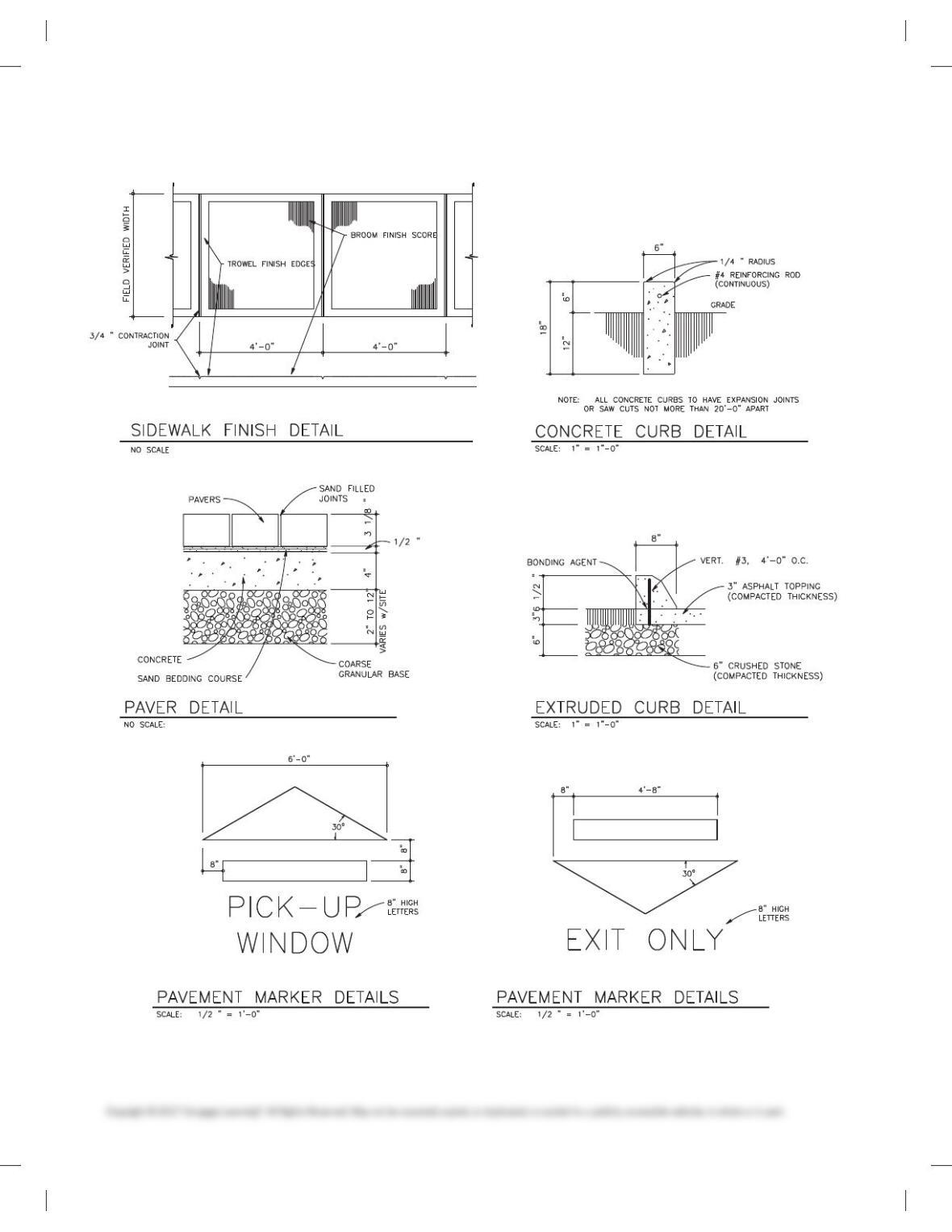
PROBLEM 22.1 Exterior pole light, sign footing, curb details,
and sidewalk and paving details
Draw the following details on one sheet unless otherwise speci-
fied by your instructor.
Drawings courtesy of Wendy’s International, Inc.
59728_ch22_EOC_ptg01.indd 3 22/02/16 11:03 am
4
PROBLEM 22.1
(Continued)
59728_ch22_EOC_ptg01.indd 4 22/02/16 11:03 am
5
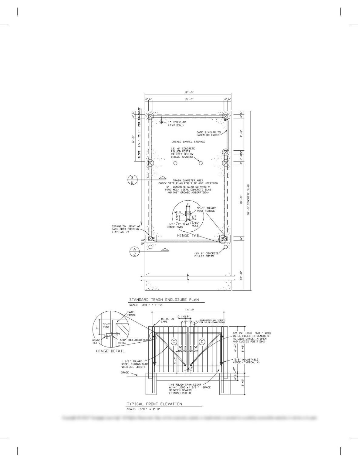
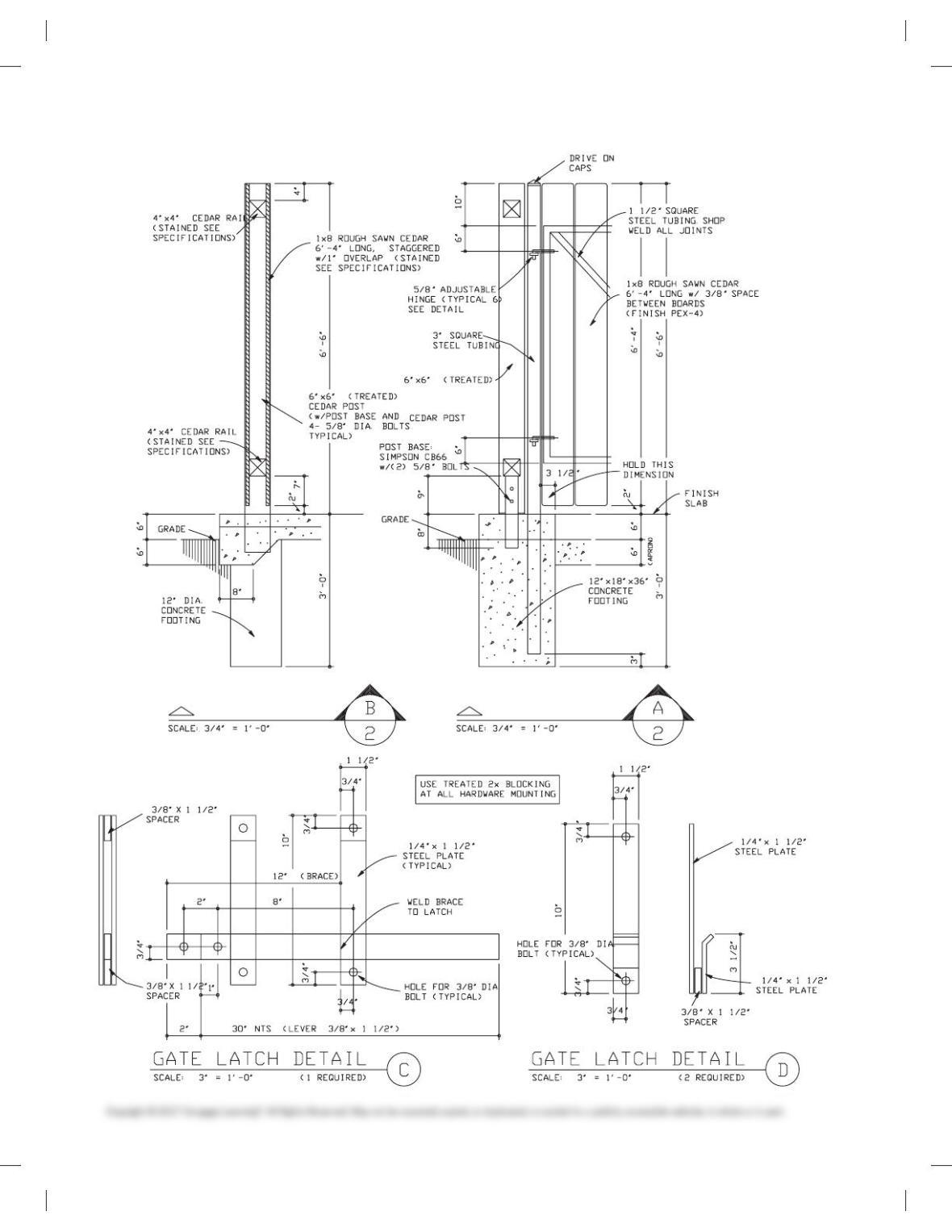
PROBLEM 22.2 Trash enclosure drawings
Given the following layouts, draw the trash enclosure plan, ele-
vation, sections, and details on one sheet, unless otherwise
specified by your instructor.
Drawings courtesy of Wendy’s International, Inc.
59728_ch22_EOC_ptg01.indd 5 22/02/16 11:03 am
6
PROBLEM 22.2
(Continued)
59728_ch22_EOC_ptg01.indd 6 22/02/16 11:03 am
7
STORAGE BUILDING
Part 2: Problems 22.3 Through 22.19
Problems 22.3 through 22.19 are the drawings for a 2,400 sq ft
storage building.
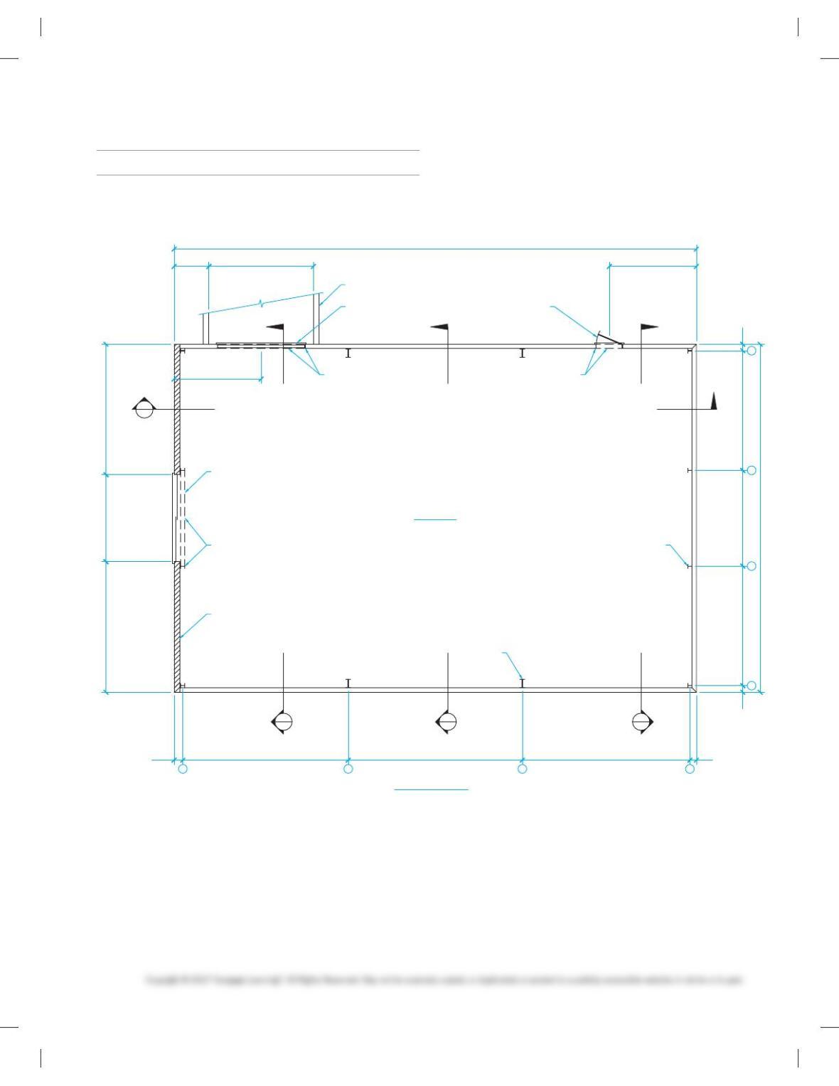
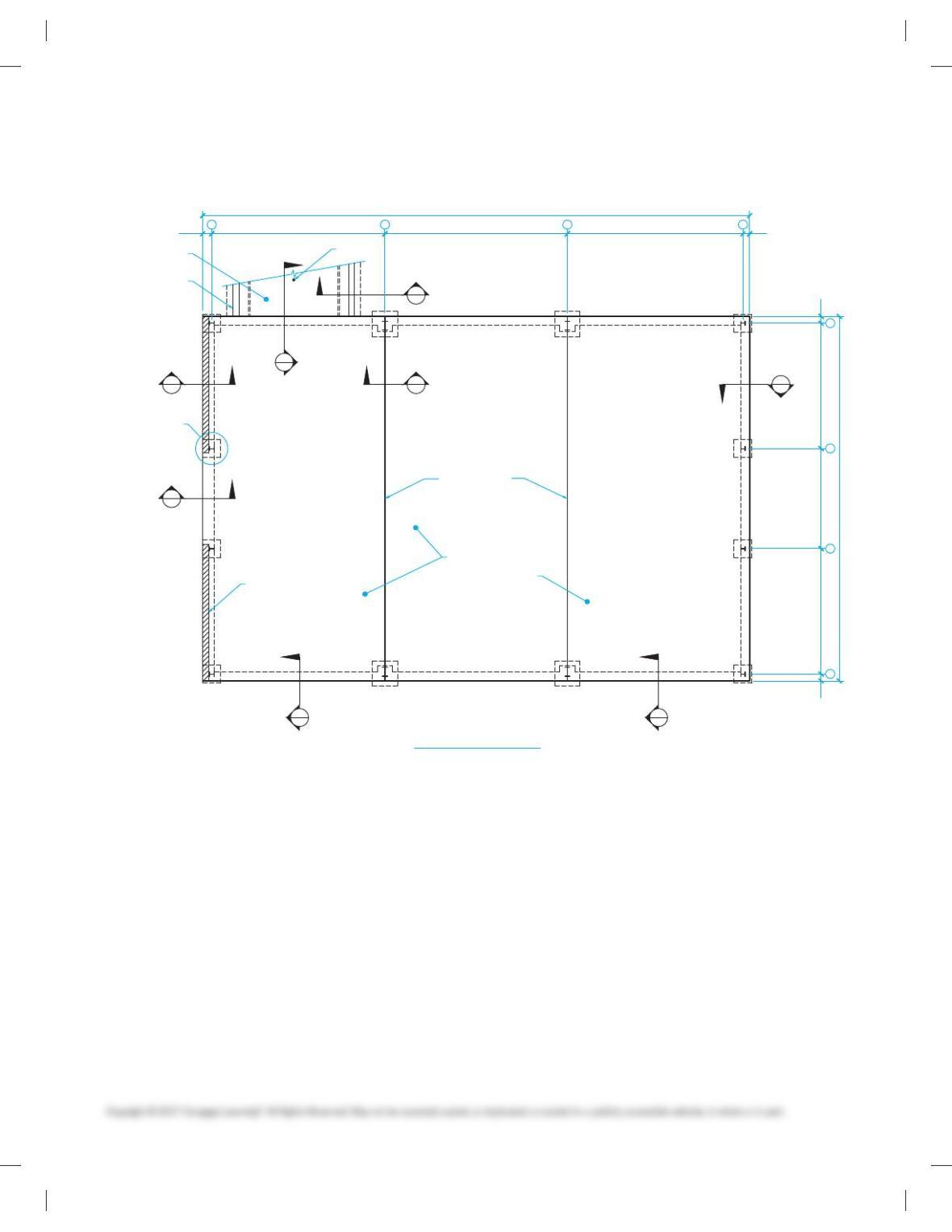
PROBLEM 22.3 Storage building floor plan
L
15′-0″ 10′-0″ 15′-0″
M K N
4′-0″ 12′-0″ 10′-0″
60′-0″
9″13′-9″11′-0″13′-9″9″
40′-0″
1′-0″ 19′-0″ 20′-0″ 19′-3″ 9″
10′-0″
1
A
W 6 X 15 TYP.
STORAGE
2400 SQ. FT.
8 X 8 X 16 GRADE
CONC. BLOCK W/
#5 VERT. @ 48″ OC
& #5 HORIZ. @48″ OC
10′ X 10′ DBL.
SLDG. DOOR
LOADING DOCK
10′ X 10′ OVERHEAD
ROLL-UP DOOR
C 6 X 13
3′ X 7′ STEEL DOOR
C 6 X 13
W X 6 X 15 TYP.
W 12 X 26 TYP.
B
C
D
2 3 4
FLOOR PLAN
59728_ch22_EOC_ptg01.indd 7 22/02/16 11:03 am
8
D
C
E A
F B
H
G
9″
13′-9″
11′-0″
13′-9″
9″
40′-0″
A
B
C
D
9″19′-3″20′-0″19′-0″1′-0″ 1 2 3 4
60′-0″
DETAIL 7
8 X 8 X 16 GRADE
CONC. BLOCK W/
#5 VERT. @48″ OC
& #5 HORIZ. @48″ OC
CONTROL JOINT
5″ CONC. SLAB W/
WWR 6 X 6 – W1.4 X W1.4
.006 VAPOR BARRIOR
8″ CONC.
RETAINING WALL
6″ CONC. SLAB W/
WWR 6 X 6 – W1.4 X W1.4 3″Ø DRAIN
FOUNDATION PLAN
GENERAL NOTES:
1. ALL CONC. TO BE 2500 PSI @28 DAYS MIN. COMP. STRENGTH.
2. ASSUME SOIL BEARING PRESSURE IS 2000 PSF.
3. LAP ALL STEEL 40 X DIA. MIN.
PROBLEM 22.4 Foundation plan
59728_ch22_EOC_ptg01.indd 8 22/02/16 11:03 am
9
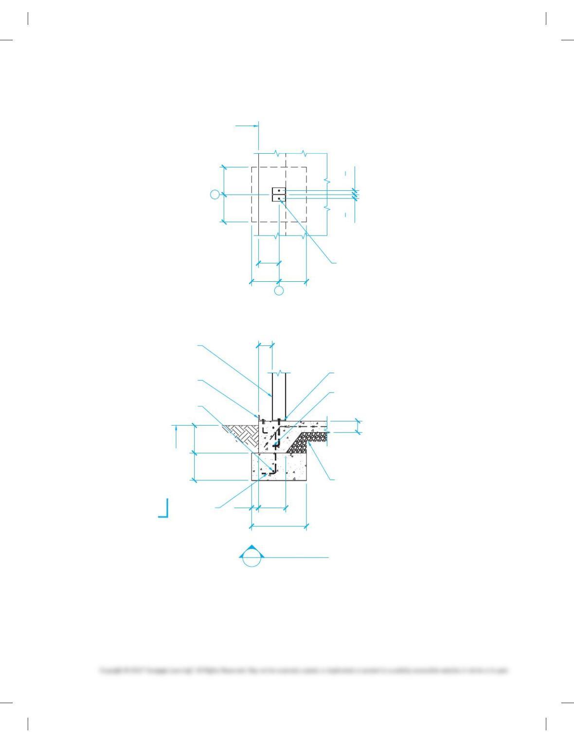
1′-0″1′-0″
1′-0″ 1′-0″
9″
FOUNDATION LINE
2 – 3/4″ X 12″ A.B.
2″ PROJ.
6″
5″
1′-0″
2′-0″
3″
1′-0″ 1′-0″
GRADE
W 6 X 15
/ 3 X 2 1/2 X 3/8
W/ 3/8″ X 6″ A.B.
@ 48″ O.C.
#5 CONT.
3 – #4 @6″ O.C.
6″
18″
P 6 X 6 X 1/4
13
4“
13
4“
4″ MIN. – 3/4″ MINUS COMPACTED
CRUSHED ROCK OVER FIRM
UNDISTURBED GRADE
2 – #4 CONT.
3″ UP / 3″ DOWN
L
4
B
A SECTION
SCALE: 3/4″ = 1′-0″
h
PROBLEM 22.5 Section A, Footing
59728_ch22_EOC_ptg01.indd 9 22/02/16 11:03 am
10
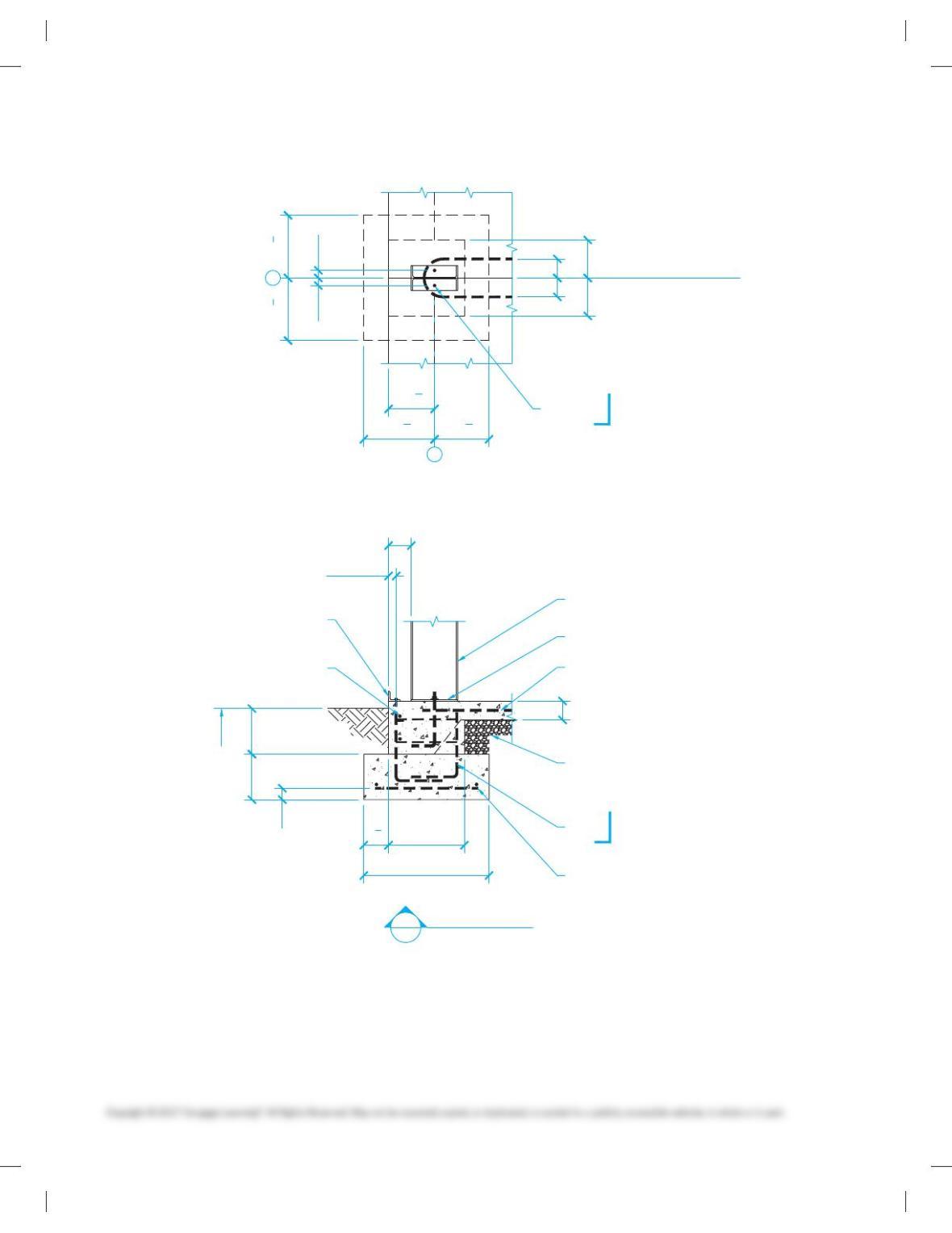
PROBLEM 22.6 Section B, Footing
1′-0″ 1′-0″
GRADE
3″
1′-8″
2′-9″
6″
61
2“
2″ MIN.
1′-4 1
2“
1′-4 1
2“
1′-6 5
8“1′-2 3
8“
1′-0 1
8“
4 – #5 HORIZ. BOTH WAYS
4 – #5 VERT. W/ #3 TIES 6″ O.C.
#5 X 16′-6″ HAIR PIN BAR
PLACE IN CENTER OF SLAB
W 12 X 26
2 – #4 CONT. 3″ UP / 3″ DOWN
/ 3 X 2 1/2 X 3/8
W/ 3/8″ X 6″ A.B.
@ 48″ O.C.
2″ 2″
5″ 5″
10″10″
RIDGED FRAME
LINE OF CONTROL JOINT
2 – 3/4″ X A.B.
2″ PROJ.
6″
15″
12″
18″
4″ MIN. – 3/4″ MINUS COMPACTED
CRUSHED ROCK OVER FIRM
UNDISTURBED GRADE
5″
P 6-1/2 X 12-1/2 X 3/8
C
L
L
D
3
B SECTION
SCALE: 3/4″ = 1′-0″
h
h
59728_ch22_EOC_ptg01.indd 10 22/02/16 11:03 am
11
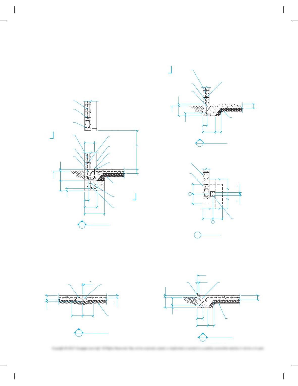
PROBLEM 22.7 Section C, Footing and concrete blocks;
Section D, Footing; Detail 7, Bond beam detail
1′-0″ 1′-0″
GRADE
3″
5″
1′-3″
1′-0″
4 – #5 CONT.
3 – #4 @ 6″ O.C.
W 6 X 15
2 – #4 CONT. 3″ UP / 3″ DOWN
4 – #5 @ BOND BEAM
24″ EA. SIDE OF OPENING
SOLID GROUT
6″
18″
4″ MIN. – 3/4″ MINUS COMPACTED
CRUSHED ROCK OVER FIRM
UNDISTURBED GRADE
2″
5″
5″
2 – 3/4″ X 12″ A.B.
2″ PROJ.
#5 HORIZ. @ 48″ O.C.
#5 VERT. @ 48″ O.C.
10′-0″
#5 VERT. 48″ O.C. LAP 48″ MIN.
CENTER GROUT ALL STL CELLS
#5 @ 16″ O.C.
2′-0″
6″
30″
P 6 X 6 X 1/4
#5 HORIZ.
@ 48″ O.C.
1′-0″
3″
5″
1′-3″
2 – #4 CONT. 3″ UP / 3″ DOWN
4″ MIN. – 3/4″ MINUS COMPACTED
CRUSHED ROCK OVER FIRM
UNDISTURBED GRADE
2″
#5 VERT. 48″ O.C. LAP 48″ MIN.
CENTER GROUT ALL STL CELLS
#5 @ 16″ O.C.
7″
6″
30″
#5 HORIZ.
@ 48″ O.C.
L
1′-0″1′-0″
1′-0″ 1′-0″
2 – 3/4″ X 12″ A.B.
2″ PROJ.
13
4“
13
4“
3/8″ GROUT JOINT
8 X 8 X 16 GRADE
CONC. BLOCK. SOLID
GROUT ALL STL CELLS
1
B
GRADE
C SECTION
SCALE: 3/4″ = 1′-0″
D SECTION
SCALE: 3/4″ = 1′-0″
DETAIL
SCALE: 3/4″ = 1′-0″
7
h
PROBLEM 22.8 Section E, Slab footing; Section F, Slab joints
1′-0″ 1′-0″
21
2“
5″
11
2“
2″
PREFORMED
CONTROL JOINT
2″
5″
6″
1′-0″ 7″
8″
1′-0″ 2″
3″
/ 3 X 2 1/2 X 3/8
W/ 3/8″ X 6″ A.B.
@ 48″ O.C.
FOUNDATION LINE
WWR 6 X 6 – W1.4 X W 1.4
2 – #4 CONT.
4″ MIN. – 3/4″ MINUS COMPACTED
CRUSHED ROCK OVER FIRM
UNDISTURBED GRADE
4″ MIN. – 3/4″ MINUS COMPACTED
CRUSHED ROCK OVER FIRM
UNDISTURBED GRADE
E SECTION
SCALE: 3/4″ = 1′-0″ F SECTION
SCALE: 3/4″ = 1′-0″
59728_ch22_EOC_ptg01.indd 11 22/02/16 11:03 am
12
PROBLEM 22.9 Section G, Loading dock ramp
PROBLEM 22.10 Sections H and J, Loading dock walls
4″ MIN. – 3/4″ MINUS COMPACTED
CRUSHED ROCK OVER FIRM
UNDISTURBED GRADE
4″ MIN. – 3/4″ MINUS
COMPACTED CRUSHED
ROCK OVER FIRM
UNDISTURBED GRADE
10′-0″
30′-0″
1′-0″
1′-0″
4′-0″
C 4′-0″
6″ CONC. SLAB
W/ WWR 6 X 6 – W1.4 X W1.4
1′-0″
1′-0″
3″ Ø DRAIN
L
J
G
SECTION
SCALE: 1/4″ = 1′-0″
8″
6″
4′-0″
2′-6″
3″
1′-0″
4″Ø FRENCH DRAIN
IN 8″ X 12″ X 1″ GRAVEL
W/ DRAIN FABRIC OVER
2″
3/8 ” X 6″ A.B. 48″ O.C.
LENGTH OF WALL FOR ATTACHING
FUTURE GUARDRAIL ASSEMBLY
#5 HORIZ. @24″ O.C.
#5 @ 16″ O.C.
# 5 @ 16″ O.C.
#5 CONT.
2″ MIN.
2″
4′-0″ MAX.
3″
1′-0″
2′-0″
8″
2- #4 CONT. 3″ UP / 3″ DOWN
#5 CONT. LAP W/ VERT.
EXTEND 18″ INTO SLAB
#5 CONT.
#5 VERT. @24″ O.C.
#5 HORIZ. CONT. @ 24″ O.C.
2 X 4 KEY 2 X 4 KEY
#5 @16″ O.C.
6″
6″
12″
24″
4″ MIN. – 3/4″ MINUS COMPACTED
CRUSHED ROCK OVER FIRM
UNDISTURBED GRADE
4″ MIN. – 3/4″ MINUS COMPACTED
CRUSHED ROCK OVER FIRM
UNDISTURBED GRADE
4″ MIN. – 3/4″ MINUS COMPACTED
CRUSHED ROCK OVER FIRM
UNDISTURBED GRADE
5″
10″
27″
H SECTION
SCALE: 3/4″ = 1′-0″
J SECTION
SCALE: 3/4″ = 1′-0″
59728_ch22_EOC_ptg01.indd 12 22/02/16 11:03 am
13
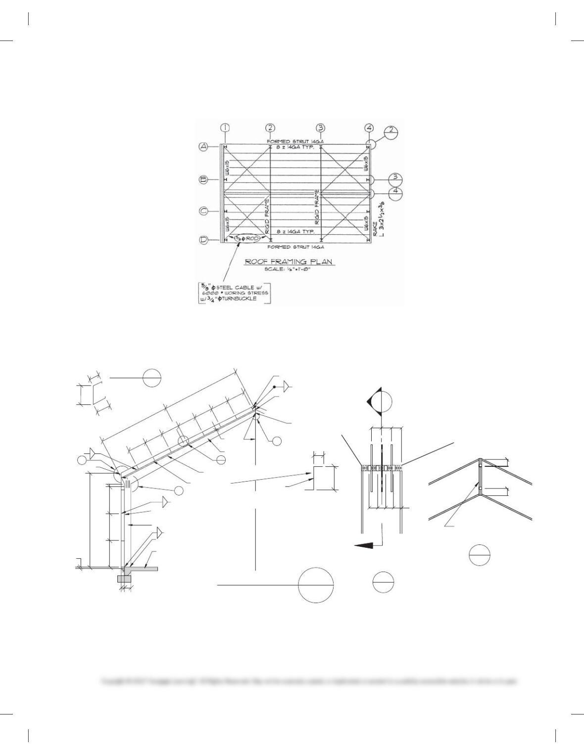
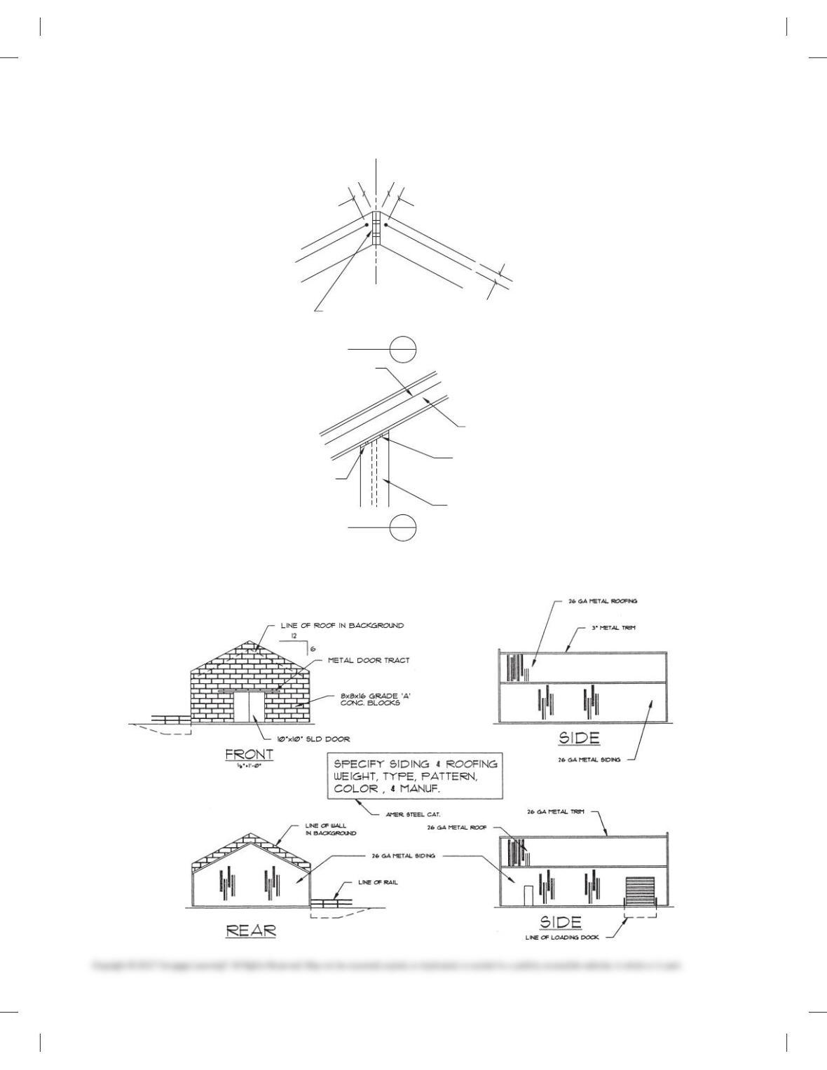
PROBLEM 22.11 Roof framing plan
KSECTION
SCALE: = 1′ – 0″
R
S
P
4 –
P
L 6″ X X O – 10
3/
4“
3/
4“
3
/8
1/2
1/2“
3/
16
3/
18
3/
8
1/21/2 3/
8
5/
8
3
/
8
3/
4“
1/2“
Ø ASTM 325 BOLTS
3/
8“
3/
4
2″ 2″
3″
2″
8″
14 GA
3″ 3″ 3″
23
/
8
23
/8
2
1
/
2
1
/
2
1
/
2
4
1
/
4
6
1
/
3
8
3
/8
2
DETAIL
C
L
P
L 6 – X 12 – X
P
L 6″ X
1
/
4
P
L 5″ X X 13′ – 0″
6
2″
6″
4″
14′ – 0″
4′ – 0″ 4′ – 0″ 4′ – 0″
12″
5″ SLAB
5
P
26 GA GALV (GI) CONT> RIDGE
Ø PIPE AT MID SPAN
4 – Ø ASTM 325 BOLTS
BEAM WEB
Ø ROD BRACING END BAYS ONLY
SEE ROOF FRAMING
14 GA PURLINS
EAVE STRUT
FLANGE FLANGE
C6 X 13
W12 X 26
6
R
PROBLEM 22.12 Section K, Typical buildings with details
59728_ch22_EOC_ptg01.indd 13 22/02/16 11:03 am
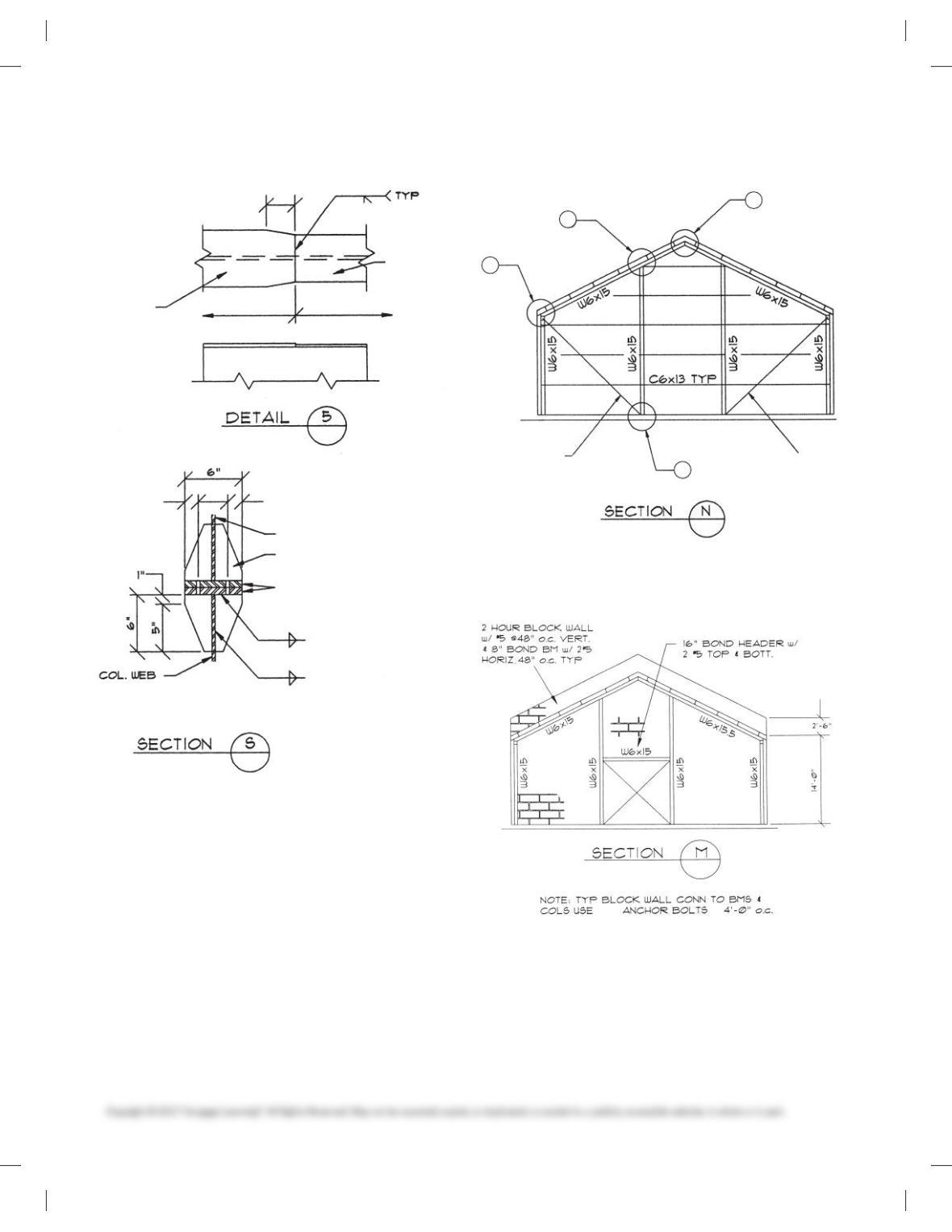
14
PROBLEM 22.13 Flange details and connections PROBLEM 22.14 End walls
5″ X 1/4″ FLANGE
3/8
6″ X 3/8″ FLANGE
FLANGE PL
6″ X 3/8″
3 1/2
3/16
3/8
1 1/4 1 1/4
FLANGE P
L
5″ X 1/4″
3″
BEAM WEB
P
L 2- 7/8″ X 3/8″ X Ø’-6″
CONNECTION P
L
6″ X 3/4″ X 1′-Ø“
w/ 8-3/4″Ø ASTM 325 BOLTS
5/8″Ø ROD
5/8″Ø ROD
1
2
3
4
3/4″Ø @
–
PROBLEM 22.15 Fire walls
59728_ch22_EOC_ptg01.indd 14 22/02/16 11:03 am
15
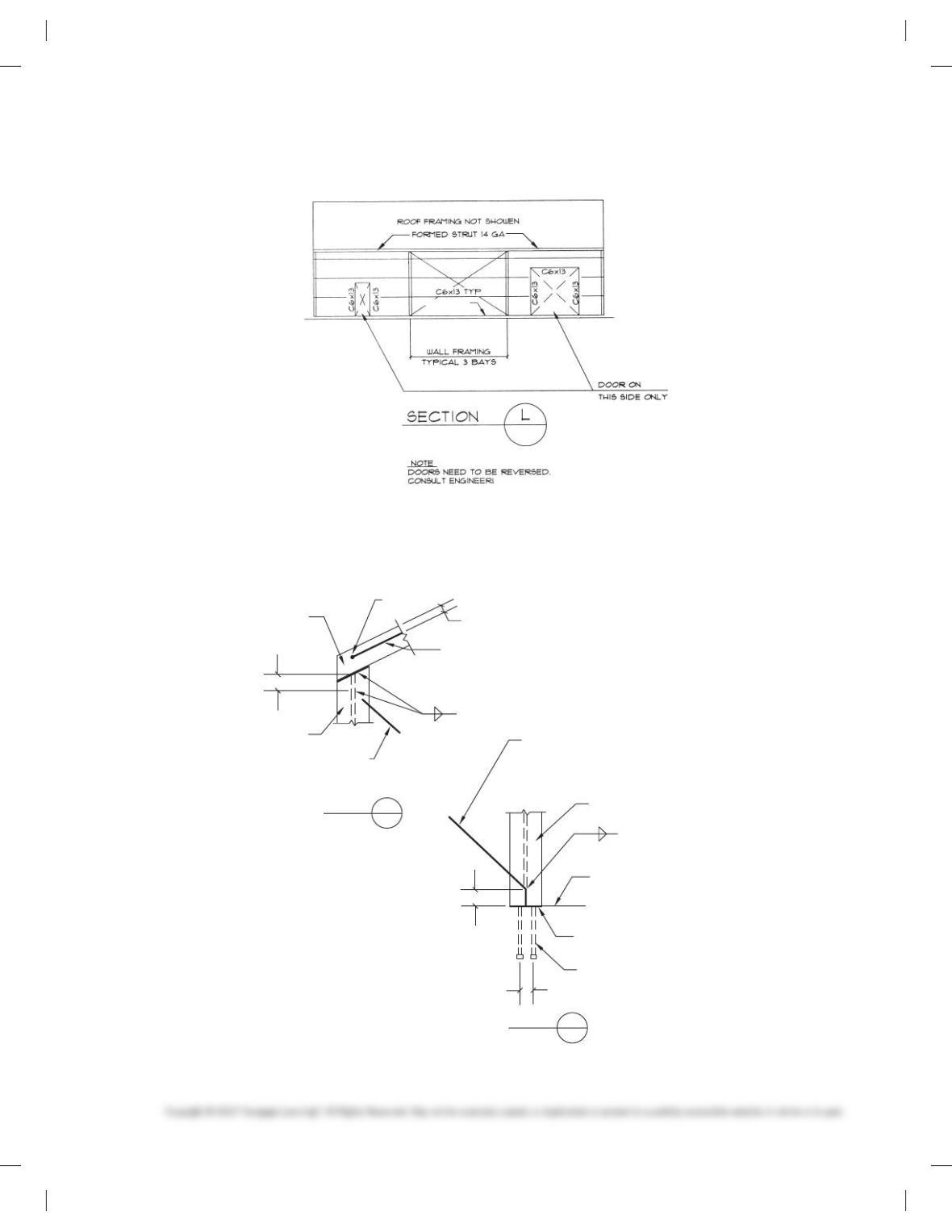
PROBLEM 22.16 Section side wall framing
PROBLEM 22.17 Column base and cap connection details
L3 x 2 1/2 x 3/8
–
5/8″ Ø ROD
WALL BRACING
W/ 3/4″ TURNBUCKLE
W6 X 15 COL.
W6 X 15 COL.
W6 X 15 BM
WELD
WELD
5/8″Ø STEEL CABLE
ROOF BRACING W/ 3/4″ TURNBUCKLE
CAP P 3/8″ X 6″ X 6″-W-2-13/16″ Ø HOLES
2-3/4″Ø BOLTS ASTM 325
5/8″ ROD
WALL BRACING
3/8
FIELD WELD
TOP /FOUNDATION
BASE P 6 X 2/3 X 6″ W/2
13/16 Ø HOLES
2-3/4″ Ø X 1’0″ ANCHOR BOLTS
4″
3 1/2″
4″
2″
3/8
L
L
DETAIL 1
DETAIL 2
Ø
59728_ch22_EOC_ptg01.indd 15 22/02/16 11:03 am
16
PROBLEM 22.18 Column cap and ridge connection details
PROBLEM 22.19 Elevations
DETAIL
BUILDING
C
3
4″ 4″
2″
2- P 3/8″ X 6″ X 7″
2-3/4″ Ø BOLTS ASTM 325
3/4″ Ø ROD
ROOF BRACING
W6 X 15 BM
W6 X 15 COL.
WELD SYMBOL
3/8″ FILLET
CAP P 3/8″ X 6″ X 6″
2-3/4″ Ø BOLTS
ASTM 325
DETAIL 4
L
L
L
59728_ch22_EOC_ptg01.indd 16 22/02/16 11:03 am
17
WAREHOUSE BUILDING
Part 3: Problems 22.20 and 22.21
Problems 22.20 and 22.21 are drawings for a warehouse facility.
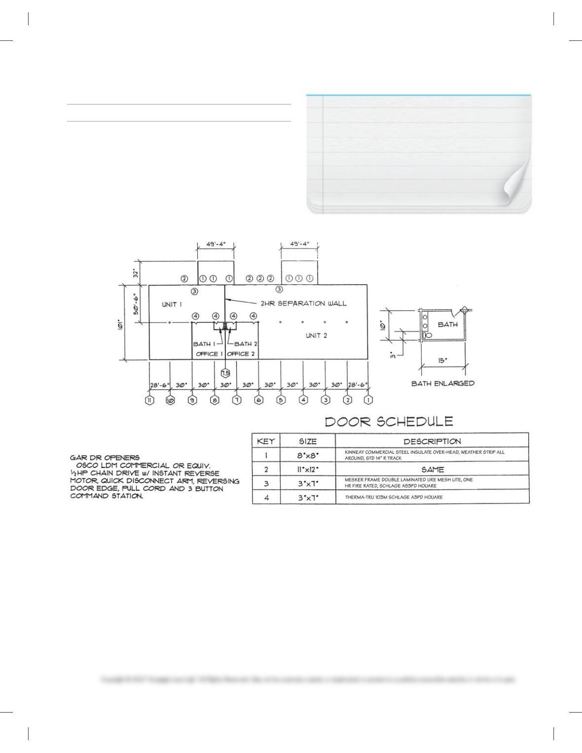
PROBLEM 22.20 Floor plan and schedules
NOTE: Alternate problems can be developed using
plumbing, electrical, and HVAC overlays after studying
Chapter 20 Electrical and Electronic Drafting, Chapter 21
Industrial Process Piping, and Chapter 23 Heating, Venti-
lating, and Air-Conditioning (HVAC) and Pattern Develop-
ment. Other drawings can be designed to complete a
set of plans based on the content of Chapter 22
Structural Drafting, if appropriate with course
guidelines.
59728_ch22_EOC_ptg01.indd 17 22/02/16 11:03 am
18
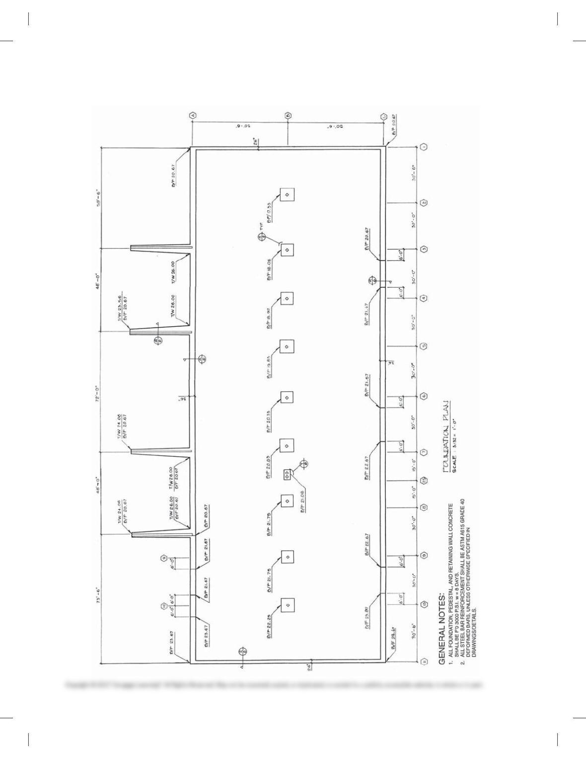
PROBLEM 22.21 Foundation plan
59728_ch22_EOC_ptg01.indd 18 22/02/16 11:03 am
19
INTERIOR ELEVATIONS AND PICTORIAL
DRAWINGS
Part 4: Problems 22.22 through 22.25
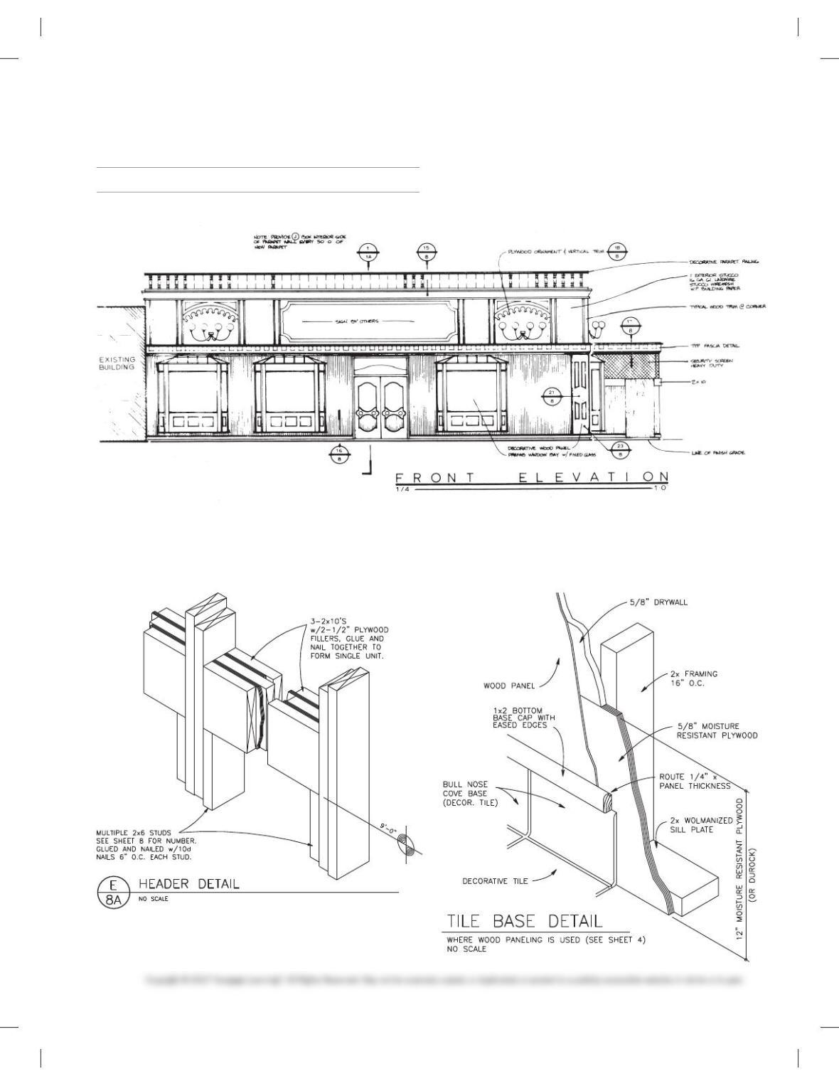
PROBLEM 22.22 Decorative interior elevations
Problems 22.23 through 22.25 are pictorial drawings. Create isometric drawings from the given problems.
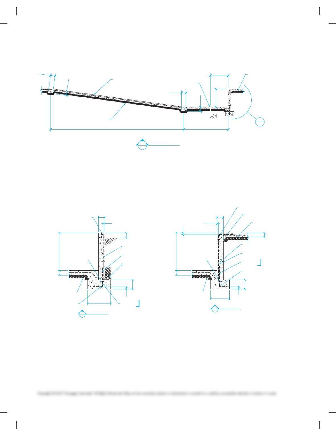
PROBLEM 22.23 Header detail
Courtesy Wendy’s International, Inc.
PROBLEM 22.24 Base detail
Courtesy Wendy’s International, Inc.
Use a scale of 3/320 5 19-00 to measure the layout shown below.
Make a 100% print of the problem page and use the hard copy to
establish dimensions. Convert to a 1/40 5 19-00 scale on appro-
priately sized vellum.
Courtesy Structureform Masters, Inc.
59728_ch22_EOC_ptg01.indd 19 22/02/16 11:03 am
20
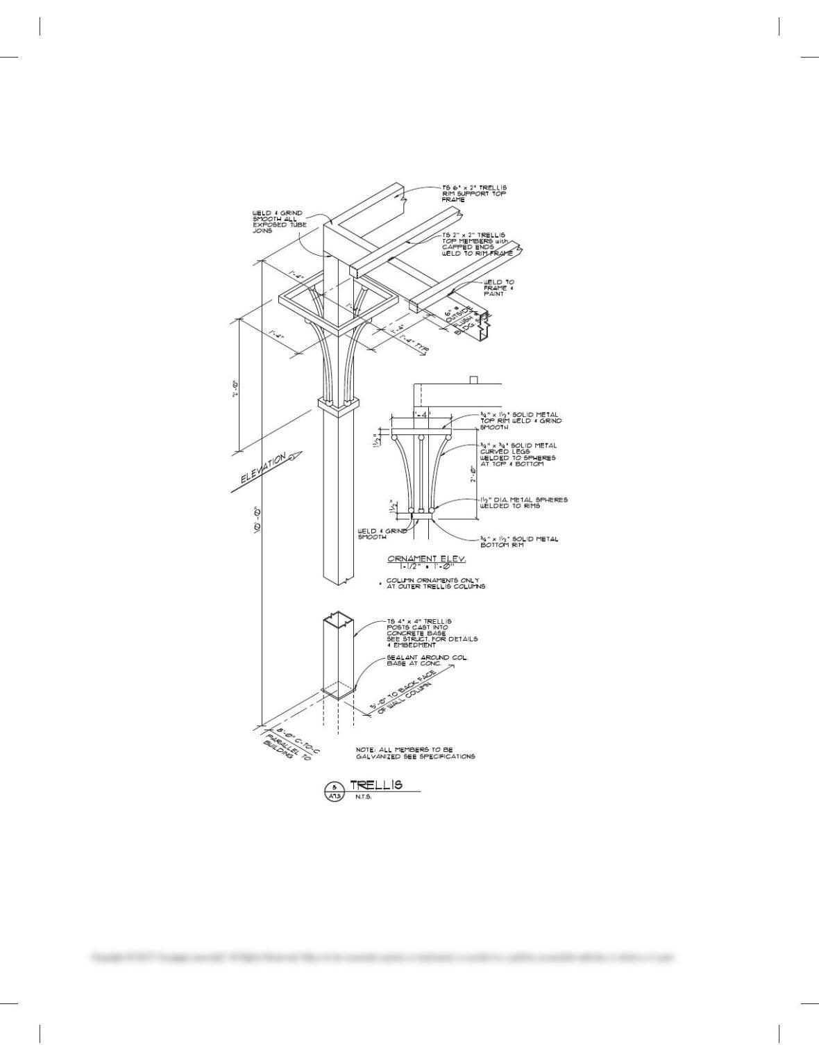
PROBLEM 22.25 Trellis detail
Courtesy Ankrom Moisan Architects.
59728_ch22_EOC_ptg01.indd 20 22/02/16 11:03 am

21
STRUCTURAL DESIGN PROBLEM
Part 5: Problem 22.26
PROBLEM 22.26 Design a 5,400-square-foot feed store and
saddle shop using the given floor plan, exterior rendering, and
3-D model on the following pages for specific information, and
use the following general requirements:
■ Main building dimensions: 909-00 3 609-00.
■ Covered shed roof entry area in front of store with 609-00 3
109-00.
■ Brick masonry veneer front face.
■ Gable roof over main building.
■ Roof slope of your choice with a minimum 5/12 pitch
suggested.
■ Research of materials and construction methods are of sig-
nificant importance for this project.
■ Construction materials and methods of your choice are based
on the contents of this chapter, unless otherwise specified
here or by your instructor.
■ Design the structure to the best of your ability, realizing that
the structure will not be properly engineered, unless you seek
the guidance of a professional structural engineer. The build-
ing is not intended to be properly engineered, but to give you
an opportunity to use available resources and your own ideas
to complete the project.
■ To the best of your ability, create a complete set of structural
drawings based on the content of this chapter.
ENVIRONMENTAL REPORTS
Part 6: Problems 22.27 Through 22.29
PROBLEM 22.27 Write and give a 250 word oral report with
graphics covering sustainable design opportunities and
practices.
PROBLEM 22.28 Write and give a 250 word oral report with
graphics covering sustainable material and water use.
PROBLEM 22.29 Write and give a 250 word oral report with
graphics covering analyzing building design for sustainable
practices.
TEAM PROBLEMS
The advanced structural design problems can be assigned as
team problems as determined by the instructor and course
objectives.
Team problems are provided that can be used as projects
that help foster leadership and cooperation between team
members to design and draw a set of plans for a building.
Teams are established with any desired number of members
based on the project and curriculum goals. Teams can select
a manager by voting in a democratic process, by selecting the
person with the highest course evaluation, or as determined
by the instructor. A manager is the person in charge of the
project. The manager coordinates the team work, monitors
the progress, and provides answers and instructions to the
team members in cooperation with the instructor. The man-
ager divides the project into tasks and assigns portions of the
project to the drafting team members. The manager works
with team members to establish design alternatives. Team
members are drafters, with one drafter responsible for sheet
layout and reproduction. Each drafter is assigned specific
drawing for the completion of the entire set of drawings. The
manager provides coordination between team members to
confirm all parts of the project match. Final team assign-
ments and members are determined by your instructor.
TEAM EVALUATION CRITERIA:
Team project evaluation includes:
Project coordination: organization of project assignments.
Project completion: complete set of working drawings.
Team member cooperation.
Project quality: drawings completed accurately and in a pro-
fessional manner.
Architectural artistic decisions:
Project properly interpreted.
Design decisions properly evaluated and completed.
59728_ch22_EOC_ptg01.indd 21 22/02/16 11:03 am