CHAPTER 21 INDUSTRIAL PROCESS
PIPING PROBLEMS
INSTRUCTIONS
1. Read problems carefully before you begin working. Select
(or your instructor can assign) one or more of the following
problems. Complete each problem on an appropriately
sized drawing sheet with border and title block as described
in this chapter or use the size indicated in the specific in-
structions, unless otherwise specified by your instructor.
2. Refer to Appendixes W and X for fitting and valve dimen-
sions. Consult with your instructor to determine if specific
vendor catalogs should be used to obtain dimensions.
3. Construct your drawings using a CADD system, if indicated
in course guidelines.
■straight tee,
■concentric reducer, and
■eccentric reducer.
Draw a front view and each of the four orthographic views (top,
bottom, left and right sides).
PROBLEM 21.2 Draw the fittings listed in Problem 21.1 in
single-line representation. Use the same NPS and the same
scale.
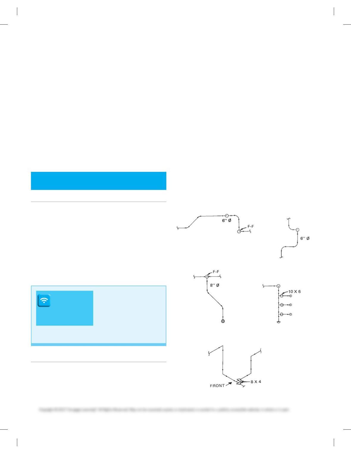
PROBLEM 21.3 Draw each of the five pipe assemblies in
double-line form. The view given is the front view. Draw each of
the other four orthographic views (top, bottom, left and right
sides). Use the following information when doing this problem:
■Draw at a scale of 3/805 19-00.
■Use the pipe diameters indicated.
■Draw the fittings to scale, but straight lengths of pipe can be
drawn proportional to the sketch.
■Pipe that appears to be extending away from the viewer
should be drawn fitting to fitting if indicated with FF on the
sketch. This means that there is no straight pipe in the run
that is going away from the viewer. Runs that do contain pipe
are not shown with F-F.
(a)
(b)
(c) (d)
(e)
DRAFTING
TEMPLATES
To access CADD template
files with predefined drafting
settings, go to the Student
Companion Website, select
Student Downloads and
Drafting Templates, and then
select the appropriate
template file.
Part 1: Problems 21.1 Through 21.15
PROBLEM 21.1 Draw the following fittings in double-line
representation. Use 80 diameter NPS and draw at a scale of 1/20
5 19-00.
■ 908 elbow,
■ 458 elbow,
59728_ch21_EOC_ptg01.indd 2 03/02/16 10:36 am
PROBLEM 21.4 Draw the assemblies shown in Problem 21.3
in single-line form. Follow the instructions given in Problem 21.3.
PROBLEM 21.5 Redraw the ground floor partial plan shown
in Figure 21.47a, page 742, on C-size media. Use the following
information:
■ Draw at a scale of 1/20 5 19-00.
■ Pipe more than 30 in diameter should be drawn in double-line
form.
■ Use line balloons to indicate pipe specifications.
■ Lettering should be 1/80 high.
Use Figure 21.47b–e, textbook pages 743–746, as references for
this drawing.
PROBLEM 21.6 Redraw section E-E, shown in Figure 21.47e,
page 746 in double-line form at a scale of 1/20 5 19-00. Use
standard dimensions for fittings and valves given in the
appendices.
PROBLEM 21.7 Draw a piping detail of the suction piping of
pump P-405 in section B-B, shown in Figure 21.47b page 743.
PROBLEM 21.8 Redraw section B-B, shown in Figure21.47b,
page 743, in single-line form at a scale of 1/20 5 19-00.
PROBLEM 21.9 Draw the section C-C shown in Figure 21.47c,
page 744 and section D-D shown in Figure 21.47d, page 745 in
single-line form. Use a scale of 3/80 5 19-00 on C-size media.
PROBLEM 21.10 Redraw section E-E, shown in
Figure 21.47e, page 746 at a scale of 1/20 5 19-00. Pipe that is
greater than 30 in diameter, draw as a single-line. Pipe less
than 30 diameter, draw as double-line.
PROBLEM 21.11 Draw isometric views of the five pipe
assemblies shown in Problem 21.3. Draw in single-line form.
PROBLEM 21.12 Draw a piping isometric of lines 10–HA–
101 in section E-E, shown in Figure 21.47e page 746. Use B-size
media.
PROBLEM 21.13 Draw a plan and elevation of 80–SH–009,
shown in Figure 21.58a, page 762 in single-line form.
PROBLEM 21.14 Draw a plan and elevation of 80–SH–009,
shown in Figure 21.58a, page 762 in double-line form.
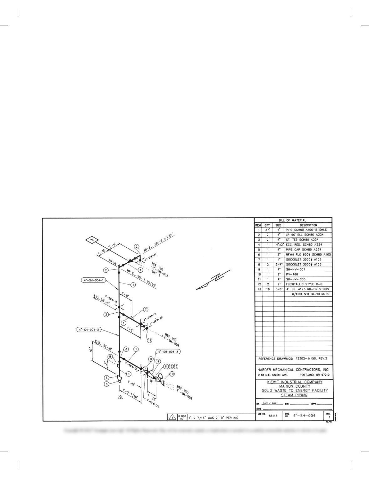
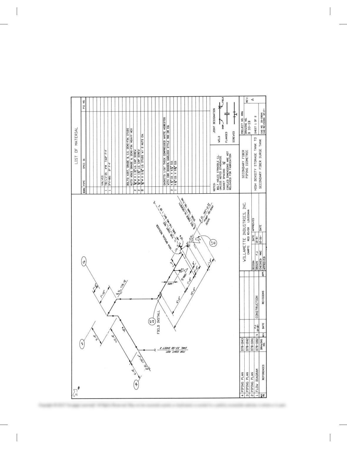
PROBLEM 21.15 Draw the spools required for the isometric
40–SH–004 shown below. Draw one per sheet of B-size media.
Include a bill of materials for each spool. The field weld con-
nection point between the two largest spools is indicated by an
X just above El. 369-60.
59728_ch21_EOC_ptg01.indd 3 03/02/16 10:36 am
Part 2: Problems 21.16 Through 21.22
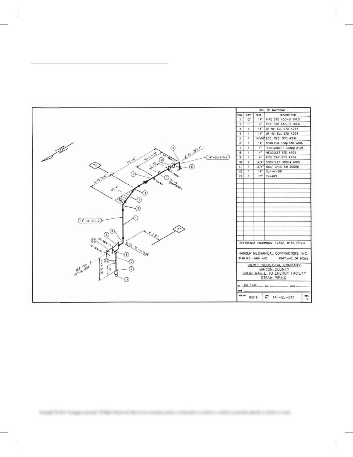
PROBLEM 21.16 Draw a plan and elevation of 140–SL–011,
shown below, in both single- and double-line forms. Place both
drawings on C-size media. Choose a scale that allows both
drawings to fit uncrowded on the sheet.
Courtesy Harder Mechanical Contractors, Inc.
59728_ch21_EOC_ptg01.indd 4 03/02/16 10:36 am
PROBLEM 21.17 Use the elevation drawing you created in
Problem 21.16 to make the following revision: Change the cen-
terline elevation from 219-4 5/80 to 209-6 3/40. Place a Delta 1
and revision cloud on the drawing with the revision note.
Note the revision on or near the drawing title block. Provide a
revision block if not currently available. Document the revision
as P21.17 and give the revision date.
PROBLEM 21.18 Draw the spools required for line 60–SH–002A
(Figure 21.12, page 724 in the textbook) on B-size sheet.
PROBLEM 21.19 Draw the spool for pipe 30–1C–102 in sec-
tion E-E (Figure 21.47e, page 746 in the textbook) from the
30 V–43 valve at elevation 569-60 to the 30 V–142 valve at ap-
proximately the 649 elevation mark. Draw no valves in the
spool. Include a bill of materials.
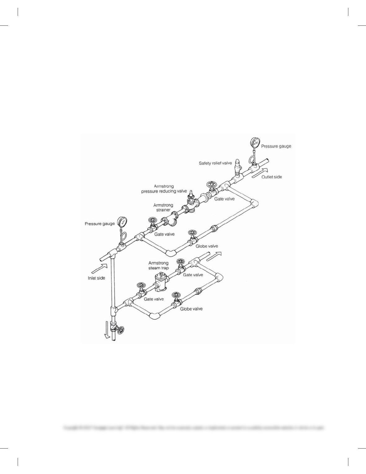
PROBLEM 21.20 Draw a plan and elevation view of the
double-line piping isometric drawing shown below. Use
threaded fittings. Have the instructor assign pipe size and di-
mensions to the problem. Draw on B-size sheet.
Courtesy Armstrong Machine Works.
59728_ch21_EOC_ptg01.indd 5 03/02/16 10:36 am
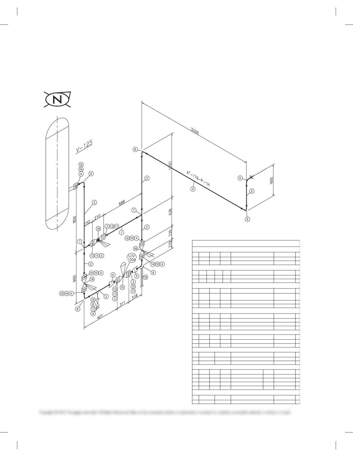
PROBLEM 21.21 Draw the piping assembly shown. The as-
sembly is shown in isometric format, and the north arrow is
pointing to the lower right of the drawing. Draw the assembly
in isometric form, and orient the drawing with the north arrow
pointing to the upper right of the drawing. Completely dimen-
sion the drawing as shown.
■ Use a B-size sheet.
■ Draw using a scale of 3/80 5 19-00 for valves and fittings and no
scale for pipe lengths.
■ Include the list of materials on your drawing.
Courtesy Willamette Industries, Inc.
59728_ch21_EOC_ptg01.indd 6 03/02/16 10:36 am

PROBLEM 21.22 Draw a plan view of the piping assembly
shown in Problem 21.21. Use break lines on the long piece of
pipe, so it fits on the drawing sheet. Draw two elevation views of
the piping assembly and place them on the same sheet as the
plan view. See your instructor for the specific views to draw.
■ Use a C-size sheet.
■ Draw using a scale of 3/80 5 19-00.
■ Show the single-line pipe and fittings as thick lines.
Part 3: Problems 21.23 Through 21.26
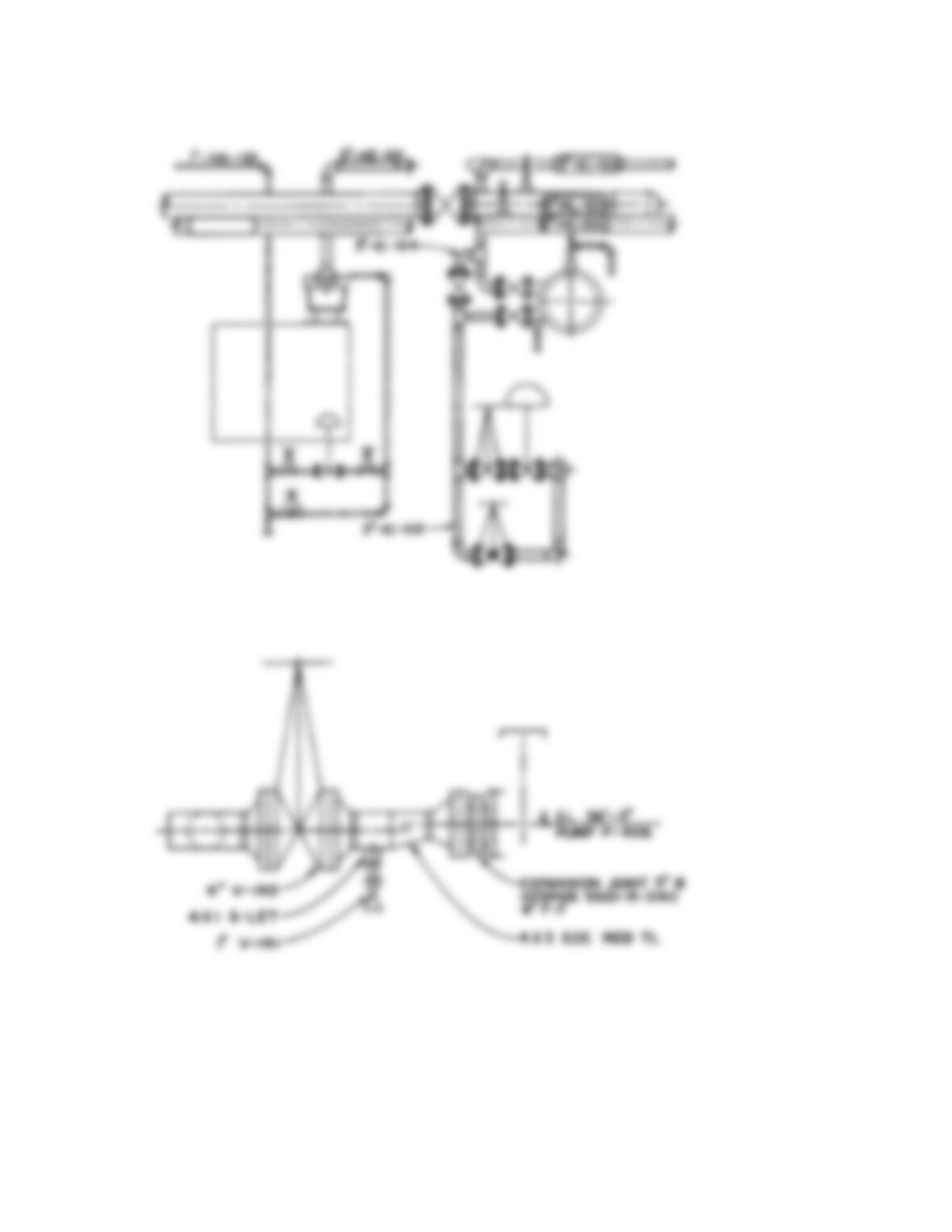
PROBLEM 21.23 Control Station 2-D
Create a 2-D drawing of the control station and bill of material
using the given drawing as a guide. Use a C-size sheet with a
border and title block as described in this chapter, unless other-
wise specified by your instructor.
Courtesy of PROCAD Software
BILL OF MATERIAL
PIPE
NUM
LENGTH
SIZE SCH. DESCRIPTION MATERIAL
S/F
1 1M 2″ STD. PIPE SMLS A106 GR. B S
2 10M 4″ STD. PIPE SMLS A106 GR. B S
FLANGES
NUM
QTY SIZE
RATING
RATING
SCH. DESCRIPTION MATERIAL
S/F
342″ 150# STD. FLANGE RF WN A105 GR. II S
4 5 4″ 150# STD. FLANGE RF WN A105 GR. II S
WELD FITTINGS
NUM
QTY SIZE SCH. DESCRIPTION MATERIAL
S/F
5 2 4″ X 2″ STD. CONC REDUCER BW ASTM A234 GR.
WPB S
66 4″ STD. ELBOW 90 DEG LR BW A234 GR. WPB S
7 2 4″ X 2″ STD. REDUCING TEE BW A234 GR. WPB S
SCREWED AND SOCKET WELD FITTINGS
NUM
QTY SIZE DESCRIPTION MATERIAL
RATING
NUM
QTY SIZE DESCRIPTION MATERIAL
S/F
811″ XS NIPPLE – 75MM LG TBE A106 GR. B F
911″ 3000# PLUG SCREWED A105 GR. II F
10 11″ ON 4″ 3000# THREDOLET A105 GR. II S
GASKETS
S/F
11 42″ 150# GASKET RF 1/8″ SPIRAL WOUND 304 SS F
12 54″ 150# GASKET RF 1/8″ SPIRAL WOUND 304 SS F
BOLTS
S/F
13 4 SETS 5/8″ X 3 1/4″ STUD BOLTS CW/2 NUTS-4/SET
A193 B7 /A194 2H
F
14 5 SETS 5/8″ X 3 1/2″ STUD BOLTS CW/2 NUTS-8/SET
A193 B7 /A194 2H
F
VALVES
TAG
S/F
15 1 2″ 150
CONTROL VALVE – D BODY
F
16 2 4″ 150# GATE VALVE RF GA101 CS F
17 1 1″ 1500# GATE VALVE SCREWED GA602 CS F
18 12″ 150# GLOBE VALVE RF GL101 CS F
NUM
QTY SIZE DESCRIPTION MATERIAL
RATING
NUM
QTY SIZE DESCRIPTION MATERIAL
NOZZLE: 150 MM PROJECTION
V–125 OD: 1200 MM
59728_ch21_EOC_ptg01.indd 7 03/02/16 10:36 am
BILL OF MATERIAL
Pipe
Num
Length Size Sch. Description Material
S/F
1 1m 2″ STD. PIPE SMLS A106 GR. B S
2 7m 4″ STD. PIPE SMLS A106 GR. B S
Flanges
Num
Qty Size
Rating
Sch. Description Material
S/F
34 2″ 150# STD. FLANGE RF WN A105 GR. II S
4 5 4″ 150# STD. FLANGE RF WN A105 GR. II S
Weld Fittings
Num
Qty Size Sch. Description Material
S/F
5 2 4″ X 2″ STD. CONC REDUCER BW ASTM A234 GR.
WPB S
6 6 4″ STD. ELBOW 90 DEG LR BW A234 GR. WPB S
7 2 4″ X 2″ STD. REDUCING TEE BW A234 GR. WPB S
Screwed and Socket Weld Fittings
Num
Qty Size Rating Description Material
S/F
8 1 1″ XS NIPPLE – 75mm LG TBE A106 GR. B F
9 1 1″ 3000# PLUG SCREWED A105 GR. II F
10 1 1″ ON 4″ 3000# THREDOLET A105 GR. II S
Gaskets
Num
Qty Size Rating Description Material
S/F
11 4 2″ 150# GASKET RF 1/8″ SPIRAL WOUND 304 SS F
12 5 4″ 150# GASKET RF 1/8″ SPIRAL WOUND 304 SS F
Bolts
Num
Qty Size Description Material
S/F
13 4 SETS 5/8″ X 3 1/4″ STUD BOLTS CW/2 NUTS-4/SET
A193 B7 /A194 2H
F
14 5 SETS 5/8″ X 3 1/2″ STUD BOLTS CW/2 NUTS-8/SET
A193 B7 /A194 2H
F
Valves
Num
Qty Size Rating Description Tag Material
S/F
15 1 2″ 150
CONTROL VALVE – D BODY
F
16 2 4″ 150# GATE VALVE RF GA101 CS F
17 1 1″ 1500# GATE VALVE SCREWED GA602 CS F
18 1 2″ 150# GLOBE VALVE RF GL101 CS F
Supports and Misc
Num
Qty Size Description Material
S/F
19 1 4″ BASE SUPPORT A106 GR. A F
PROBLEM 21.24 Control Station Isometric
Create an isometric drawing of the control station and bill of
material using the given drawing as a guide. Use a C-size sheet
with a border and title block as described in this chapter, unless
otherwise specified by your instructor.
Courtesy of PROCAD Software
59728_ch21_EOC_ptg01.indd 8 03/02/16 10:36 am
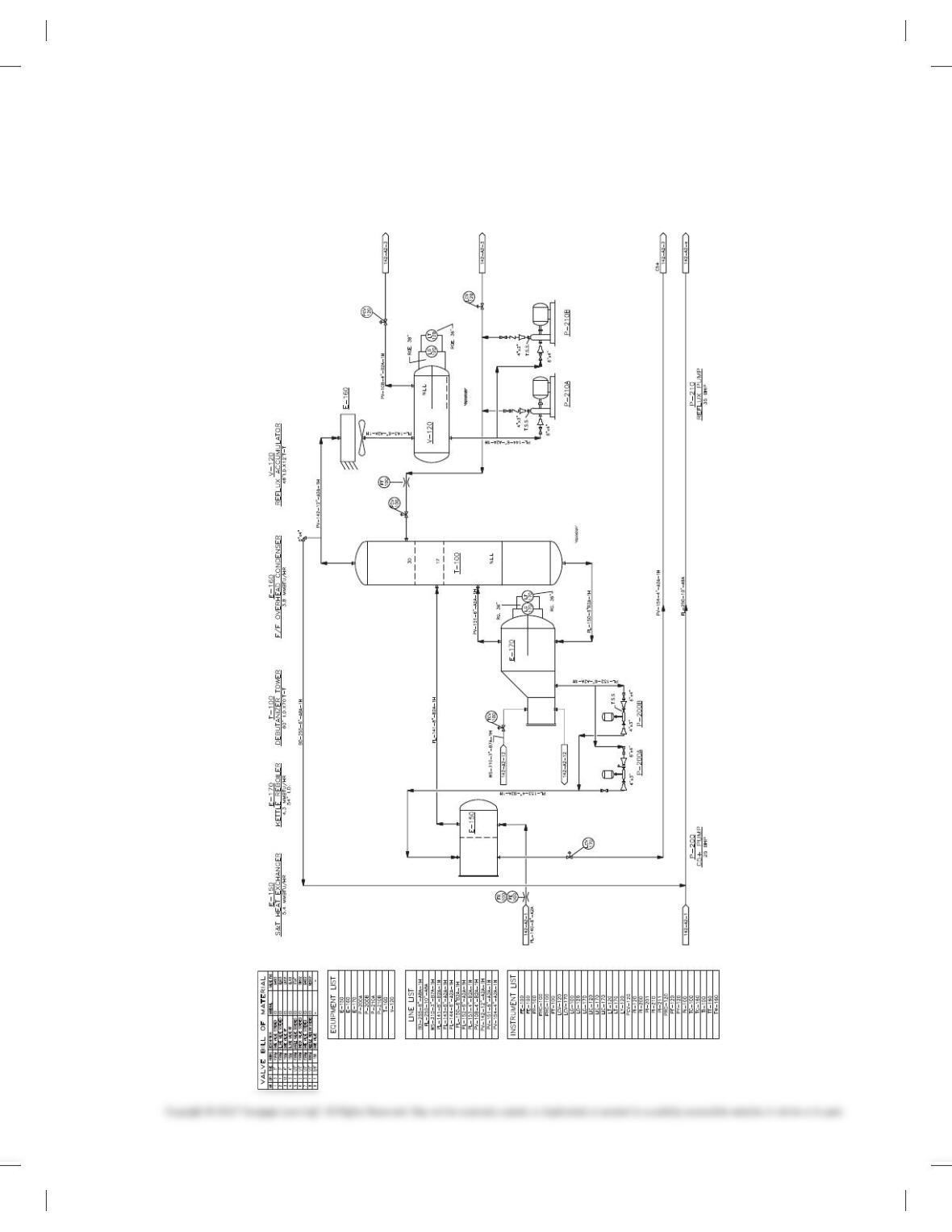
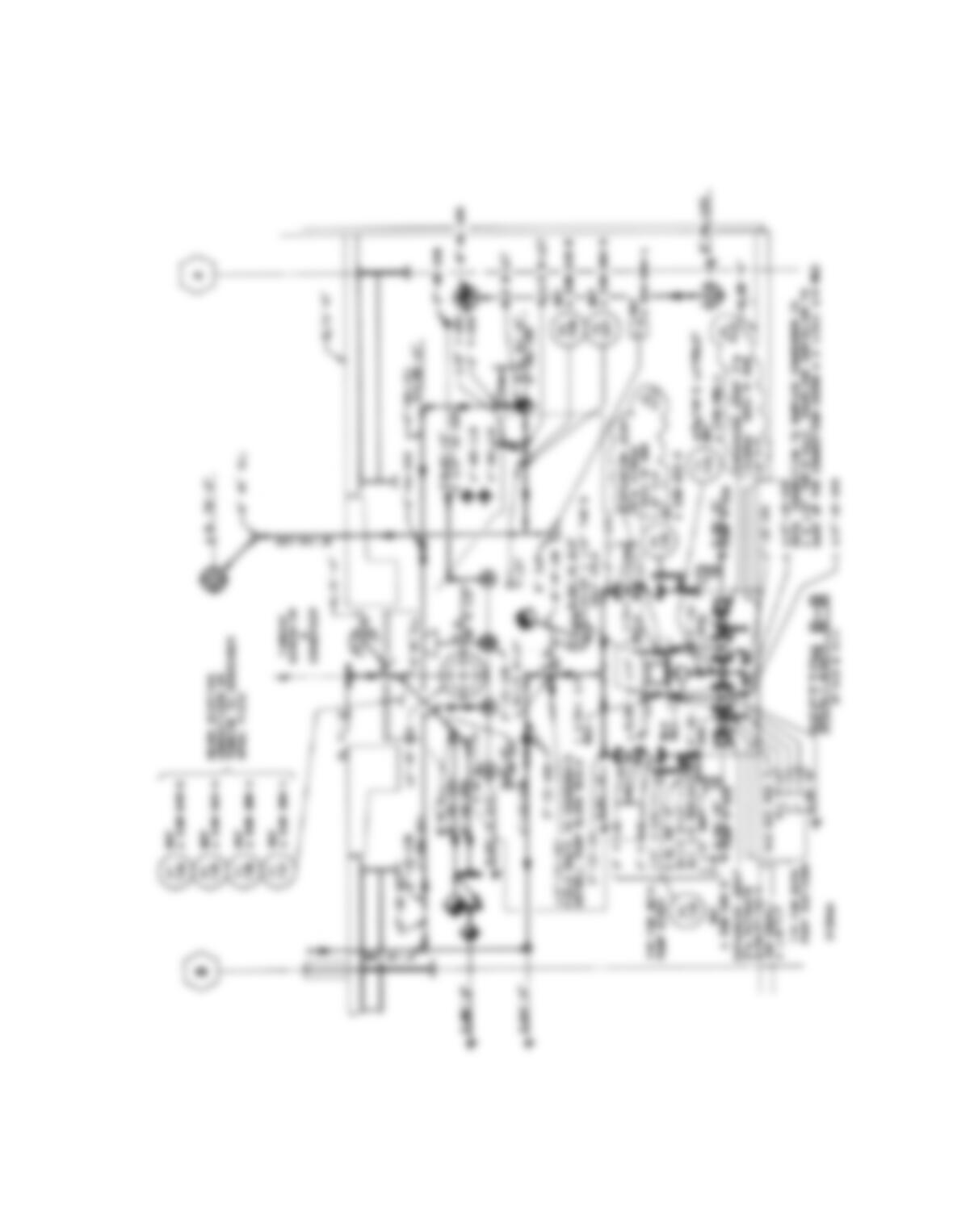
PROBLEM 21.25 Refinery PFD
Create a PFD drawing of the refinery using the given drawing as
a guide. Include the valve bill of material, equipment list, line list,
and instrument list. Use a D-size sheet with a border and title
FLARE HEADER
SEP. LIQUID
STEAM IN
STEAM OUT
FLARE HEADER
BUTANE
PROPANE
block as described in this chapter, unless otherwise specified by
your instructor.
Courtesy of PROCAD Software
59728_ch21_EOC_ptg01.indd 9 03/02/16 10:36 am
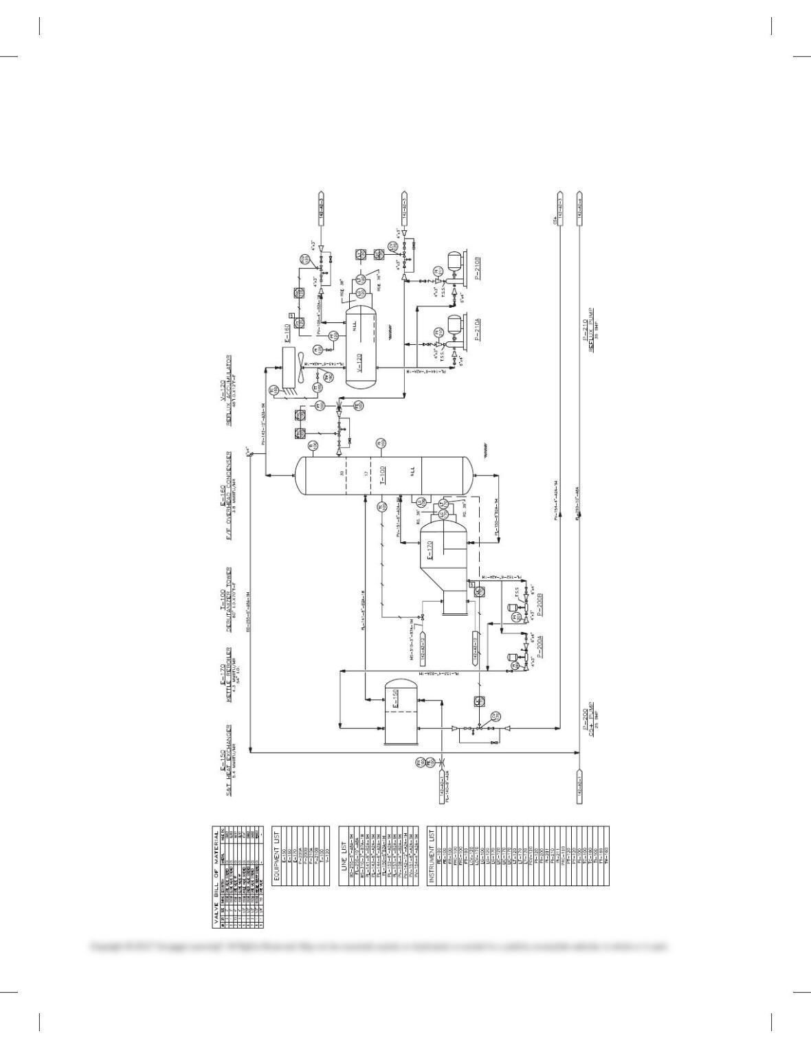
PROBLEM 21.26 Refinery P&ID
Create a P&ID drawing of the refinery using the given drawing as
a guide. Include the valve bill of material, equipment list, line list,
and instrument list. Use a D-size sheet with a border and title
FLARE HEADER
SEP. LIQUID
STEAM IN
STEAM OUT
FLARE HEADER
BUTANE
PROPANE
block as described in this chapter, unless otherwise specified by
your instructor.
Courtesy of PROCAD Software
59728_ch21_EOC_ptg01.indd 10 03/02/16 10:36 am
MATH PROBLEMS
Part 4: Problems 21.27 Through 21.29
Refer to Appendices W and X for fitting, flange, and valve dimen-
sions to solve the following problems.
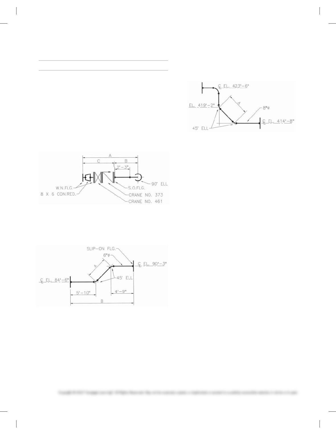
PROBLEM 21.27 The drawing shown below is an assembly
of pipe, fittings, flanges, and valves. Only one dimension is
given for the short, straight length of pipe. This dimension is
the length of pipe between two welds. You are to provide all of
the missing dimensions. Gaskets are inserted between flanges
and valves. All gaskets are 1/160 thick. Use Appendix Y to find
dimensions for valves and fittings.
A 5
B 5
C 5
PROBLEM 21.28 You are given a run of pipe shown below.
Using the dimensions shown, provide the missing dimensions.
Write your answers in the spaces provided.
A 5
B 5
PROBLEM 21.29 Calculate the travel of the angled pipe
shown in the figure below. Write your answer in the space
provided.
A 5
59728_ch21_EOC_ptg01.indd 11 03/02/16 10:36 am

388
Chapter 21
Industrial Process Piping
Solutions to End-of-Chapter Problems
Part 1: Problems 21.1 Through 21.15
PROBLEM 21.1
PROBLEM 21.2
389
PROBLEM 21.3
390
PROBLEM 21.4
391
PROBLEM 21.5 Instructor should evaluate for proper use of given information and
392
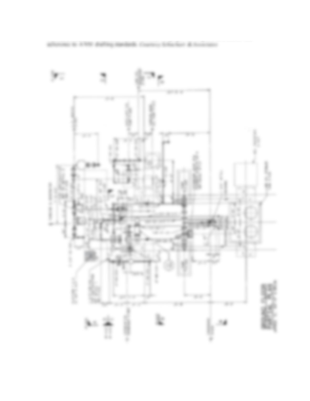
PROBLEM 21.6 Courtesy Schuchart & Associates
PROBLEM 21.7
393
PROBLEM 21.8 Instructor should evaluate for proper use of given information and
adherence to A NSI drafting standards. Courtesy Schuchart &Associates